Home Blog Page 3

Siemens S7 300 PLC Discontinued Migration Guide for Engineers

0
Siemens S7 300 PLC Discontinued Migration Guide for Engineers
Table of Contents

For more than two decades, the Siemens S7 300 PLC dominated industrial automation across manufacturing plants, water treatment facilities, power stations, pharmaceutical plants, oil and gas installations, food factories, OEM machinery, and process industries.

From small standalone machine control to large distributed automation systems, the S7 300 platform became the engineering standard for thousands of industrial facilities worldwide.

Many engineers built entire careers around:

  • STEP7 V5.x programming
  • PROFIBUS DP networks
  • ET200M remote I/O systems
  • WinCC Flexible HMIs
  • STL and AWL programming
  • PID loop control
  • Modular distributed architectures

Even today, many factories continue running 15 to 20 year old S7 300 systems without major issues.
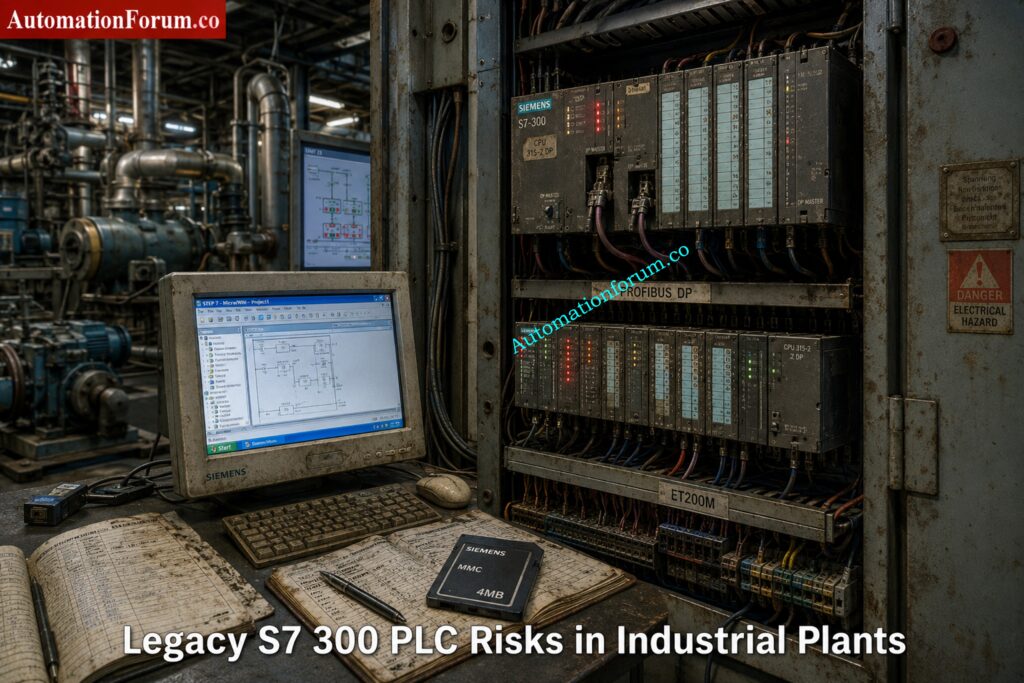
That is exactly why the current situation is becoming critical.

Plants are now facing:

  • Legacy system risk
  • Spare parts shortages
  • Unsupported engineering software
  • Aging PROFIBUS infrastructure
  • Cybersecurity exposure
  • Increasing downtime probability
  • Limited hardware availability
  • Difficulty finding experienced STEP7 engineers

For many industrial facilities, the biggest danger is not PLC failure.

The biggest danger is unexpected production shutdown with no recovery strategy.

Modernization is no longer optional.

It is becoming a plant survival requirement.

Stop Using Old PLCs Before These Failures Hit: Siemens LOGO! 9 Explained: Features, Benefits and Comparison with Older Siemens Controllers

Siemens S7 300 PLC Discontinued Migration Guide for Engineers

The phrase “Siemens S7 300 discontinued” often creates confusion among engineers and maintenance teams.

The reality is more nuanced.

Siemens introduced lifecycle management phases for automation products long before complete discontinuation. The S7 300 platform went through many lifetime stages, such as active sales, phase-out, spare-part support, and repair availability.

Siemens’ migration guidelines and lifecycle planning materials highly encourage moving to contemporary platforms like the S7 1500 for future sustainability.

Lifecycle PhaseMeaning
Active ProductFully supported and actively sold
Phase OutGradual reduction in sales and availability
Spare Part PhaseLimited availability mainly for maintenance
ObsoleteProduct no longer supported

Many engineers misunderstand the difference between discontinued and obsolete.

A discontinued PLC may still function perfectly for years.

However, risks increase rapidly when:

  • Spare CPUs become expensive
  • PROFIBUS cards disappear from stock
  • MMC cards fail
  • Legacy HMIs become unsupported
  • STEP7 compatibility issues appear on modern Windows systems

This is why modernization planning matters now instead of waiting for a plant emergency.

Master Siemens TIA Counters Before Your Next Project: How to use Siemens TIA Portal to create Different Counter blocks in PLC?

Many S7 300 CPUs and communication cards now cost significantly more in secondary markets than they did when originally released.

Critical modules such as:

  • CP343 communication processors
  • FM modules
  • PROFIBUS cards
  • ET200M interfaces
  • Analog input cards

are becoming difficult to source.

In some plants, maintenance teams already purchase used modules from third party suppliers just to maintain operations.

That creates major reliability concerns.

Many facilities still rely on:

  • STEP7 V5.5
  • WinCC Flexible 2008
  • Windows XP engineering stations

This creates severe operational problems including:

  • Hardware driver incompatibility
  • USB adapter failures
  • Licensing problems
  • Virtual machine dependency
  • Cybersecurity exposure

Modern IT departments increasingly reject unsupported operating systems on industrial networks.

PROFIBUS networks still work reliably in many factories.

However, aging connectors, grounding issues, cable degradation, and network loading problems are becoming more common every year.

Many troubleshooting engineers report intermittent communication faults that only appear during production peaks.

These issues become extremely difficult to diagnose in legacy systems.

One hidden industrial risk is engineering knowledge loss.

Younger automation engineers are increasingly trained on:

  • TIA Portal
  • S7 1500
  • PROFINET
  • OPC UA
  • Unified HMI
  • Industrial Ethernet

Very few engineers now specialize deeply in:

That creates long term maintenance risk.

Hidden Reason Behind 75 Ohm ControlNet Resistors: Why 75 Ohm Termination Resistor is Used in ControlNet?

Most existing plants follow a familiar architecture.

  • S7 300 CPU
  • ET200M remote I/O
  • PROFIBUS DP backbone
  • WinCC Flexible panels
  • MCC communication
  • VFD integration
  • Third party Modbus gateways
  • SCADA communication
  • Batch systems
  • PID control loops

A water treatment plant may contain:

  • CPU315 2DP
  • Multiple ET200M panels
  • PROFIBUS connected VFDs
  • SCADA interface
  • Remote pumping stations
  • GSM telemetry
  • Analog instrumentation
  • Hardwired interlocks

A pharmaceutical plant may additionally include:

  • Batch control
  • Recipe handling
  • Audit trail requirements
  • Redundant servers
  • Safety interlocks
  • Validation documentation

Migration complexity increases significantly depending on these integrations.

Why ControlLogix 5590 Is Dominating Smart Manufacturing: ControlLogix 5590 Explained: Next-Gen PLC for Smart Manufacturing
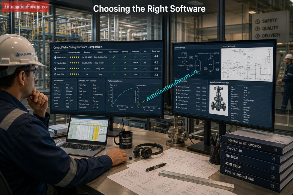
Choosing the right migration target is not just about replacing hardware. It is about matching the new controller to the plant structure, the network architecture, the future maintenance model, and the amount of downtime the plant can tolerate. Siemens’ migration guide makes the same point clearly: migration planning should consider the whole plant, not only the PLC rack, because the final system may require changes in hardware, software, communication, HMI, and service strategy.

  • The S7 1200 is the better target for smaller applications where the control task is relatively compact and the architecture is not heavily distributed. 
  • It is a good fit for small standalone machines, OEM equipment, and systems with limited I/O, limited networking, and straightforward logic. 
  • In other words, it is ideal when the machine needs a modern controller, but does not need the scale or engineering depth of a larger plant platform. 
  • Siemens positions the S7 1200 as the basic controller class, while the S7 1500 is the advanced controller class.
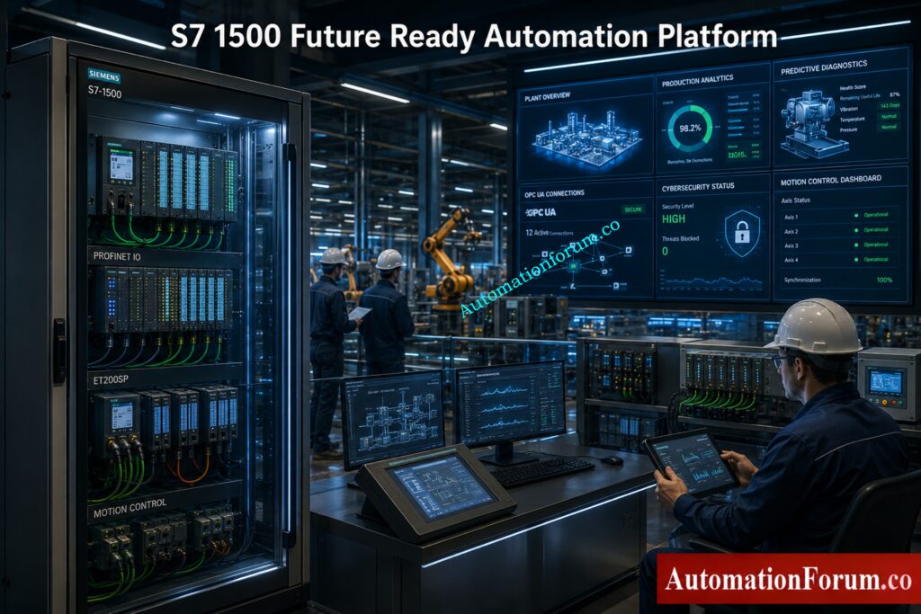
  • The S7 1500 is the preferred migration target for most industrial plants because it is built for higher performance, stronger diagnostics, modern communication, and long term modernization. 
  • Siemens highlights features such as Ethernet communication, PROFIBUS and PROFINET communication, integrated web server, integrated technology, integrated system diagnostics, industrial security functions, and safety versions for the CPU family. 
  • It also supports motion control and provides an integrated display for local diagnostics and operator support.
  • For migration projects, this matters because the S7 1500 is not just a newer CPU. It changes the maintenance experience. 
  • Symbolic programming, optimized blocks, larger memory, built in diagnostics, and stronger security features make the plant easier to support over time. 
  • Siemens also notes that the S7 1500 offers much larger memory capacity and modern software handling compared with S7 300 and S7 400 systems.
  • ET200SP is a strong choice when the plant needs a compact, modular distributed I O system with modern PROFINET based communication. Siemens describes ET200SP as a control cabinet solution with IP20 protection and fine modular construction. It supports both PROFIBUS and PROFINET, and it is integrated in TIA Portal. That makes it especially useful for compact cabinets, machine sections, and modern distributed installations where space, wiring simplicity, and diagnostics matter.
  • ET200MP is the right option when you want to modernize a traditional S7 300 style rack architecture without losing the feel of a centralized cabinet design. 
  • Siemens lists ET200MP as a control cabinet, IP20, multi channel distributed I O platform, and it can connect via PROFIBUS or PROFINET while remaining integrated in TIA Portal. 
  • That makes it a practical replacement where the original plant structure is rack based, but you still want a cleaner route into the S7 1500 ecosystem.

A simple way to choose is this:

  • choose S7 1200 for small and self contained machine control
  • choose S7 1500 for most plant modernization projects
  • choose ET200SP for compact distributed stations
  • choose ET200MP for rack like centralized modernization with better future support

Siemens also recommends planning migration by evaluating the whole installed base, communication dependencies, third party systems, and the final plant target, not by looking only at one controller in isolation.

PLC Documentation Mistakes That Cause Dangerous Plant Trips: PLC Alarm and Trip Documentation Procedure – EPC PLC Automation Engineer Guide

FeatureS7 300S7 1500
Engineering PlatformSTEP 7 ClassicTIA Portal
CommunicationPROFIBUS focusedPROFIBUS and PROFINET native
DiagnosticsLimitedIntegrated system diagnostics
Web ServerExternal or not available in the same wayIntegrated web server
SecurityBasicIntegrated industrial security functions
MemoryLower capacityMuch larger memory and bigger block support
Motion ControlUsually external or separateIntegrated technology and motion functions
OPC UALimitedNative ready for modern integration scenarios
PerformanceModerateHigher system performance
DisplayNoneIntegrated local display on many CPUs
Programming StyleHeavy absolute addressing and legacy patternsSymbolic, optimized, more maintainable
Future SupportDeclining lifecycleDesigned for long term modernization
Industry 4.0 ReadinessLimitedStrong fit for connected plants
Siemens S7 300 PLC Discontinued Migration Guide for Engineers - Why S7 1500 Is Better for Industry 4.0 Integration

The technical gap is larger than it first appears. Siemens explains that S7 1500 uses optimized blocks, symbolic addressing, much larger data blocks, new data types, integrated diagnostics, versioned libraries, access protection, and modern online functions such as trace and complete uploads.

The biggest practical difference is this: S7 300 is usually maintained as a legacy platform, while S7 1500 is engineered to become the future operating standard. That is why the S7 1500 architecture provides major engineering advantages beyond simple hardware replacement.

PLC Resolution Secrets Every Automation Engineer Must Learn: Resolution in PLCs – The Complete Guide for Automation & Instrumentation Engineers

Siemens S7 300 PLC Discontinued Migration Guide for Engineers - Complete Siemens S7 300 Migration Strategy
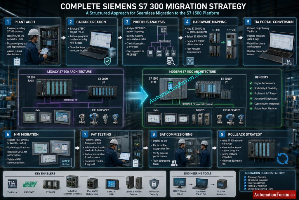
Start with a full plant audit before touching hardware or software. This is where many migration projects succeed or fail.

Document every connected item, including:

  • PLC hardware and CPU type
  • Firmware versions
  • Signal modules and communication modules
  • Network topology
  • HMI panels and operator stations
  • Third party devices and gateways
  • Analog instruments
  • Drives and motor starters
  • Safety components
  • Remote I/O stations
  • Existing cabinets, marshalling, and field wiring

A proper audit is not just a list of parts. It is a map of how the plant really works. Siemens specifically recommends identifying the status quo of the plant and analyzing all components, including third party systems and communication dependencies.

Scaling Analog Signals Correctly in PLC Automation Systems: Scaling Analog Values in Industrial Automation (PLC)

Before any migration, create complete and verified backups of everything that may be needed for recovery.

Backup items should include:

  • STEP 7 project files
  • CPU uploads
  • MMC card contents
  • HMI projects
  • SCADA project archives
  • Drive parameter files
  • Communication settings
  • Recipe and batch data
  • Alarm archives and historical data

Do not rely on a single backup copy. Keep one local, one external, and one archived version.

Many migration failures happen because the plant has an old project, but not a verified project. There is a big difference between having a file and having a backup that can actually restore the system after a fault.

Best practice:
Test the backup before migration day. A backup that has never been opened or restored is only a hope, not a recovery plan.

The network is often where hidden migration problems appear first.

Check the following:

  • PROFIBUS loading and bus health
  • Cable shielding and grounding
  • Connector condition
  • Repeaters and segment limits
  • Switches and managed Ethernet devices
  • IP address planning
  • Device naming rules
  • Communication watchdogs and timeout settings

Legacy PROFIBUS systems may look stable, but once the new PLC is installed, timing and communication behavior can change. That is why the network must be checked before hardware mapping begins.

Practical warning:
A plant can have good process equipment and still fail a migration because of weak grounding, bad connectors, or a noisy bus segment.

Once the audit is complete, map every old device to a modern target.

Typical migration paths include:

  • ET200M to ET200SP
  • PROFIBUS to PROFINET
  • WinCC Flexible panels to Comfort Panels
  • Legacy communication modules to integrated Ethernet based options
  • Rack based architectures to modular distributed architectures

This step is more than choosing an equivalent part number. It is about deciding whether the old architecture should be preserved, simplified, or redesigned.

Siemens notes that partial migration, complete migration, or phased migration may all be valid depending on plant complexity, downtime tolerance, and future expansion plans.

Engineering tip:
If the plant still depends on old I/O or old communication structure, a phased migration is often safer than a full cutover.

Simple PLC Motor Starter Logic Engineers Must Understand: PLC Program for Motor Starter with Low-Level Switch Interlock

Software conversion is where many projects become more difficult than expected.

A good migration must include:

  • Code analysis
  • STL and AWL review
  • Addressing review
  • Library restructuring
  • Block naming cleanup
  • PID loop review
  • Sequence logic validation
  • Data block conversion
  • Symbolic programming strategy

Siemens recommends reviewing the project carefully before migration and using the readiness check tool where needed. It also notes that some older structures may need adjustments after conversion, especially when special instructions, options, or unsupported components are used.

Important reality:
Direct conversion is not always the best engineering choice. In many cases, rewriting selected blocks in a cleaner TIA Portal structure gives better long term maintainability than carrying forward every old programming habit.

PLC Data Type Mistakes Destroying Industrial Automation Projects: PLC Data Types Every Automation Engineer Must Know to Avoid Costly Programming Errors

HMI work is often underestimated because it looks smaller than the PLC migration, but in practice it can consume a large part of the project schedule.

HMI migration may include:

  • Alarm mapping
  • Tag remapping
  • Recipe conversion
  • Historical data migration
  • Screen redesign
  • Navigation changes
  • User access updates
  • Language changes
  • Trend and archive conversion

Siemens’ migration guide also points out that older panels are discontinued and recommends moving to more modern HMI families such as Basic or Comfort Panels, with version compatibility requirements for project migration.
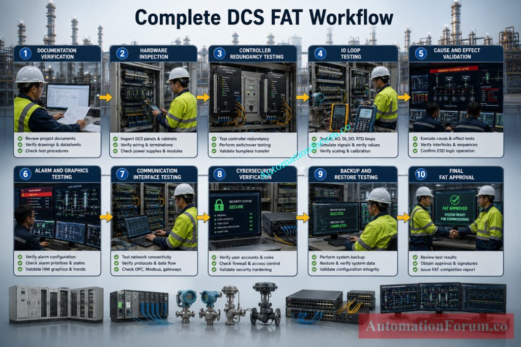
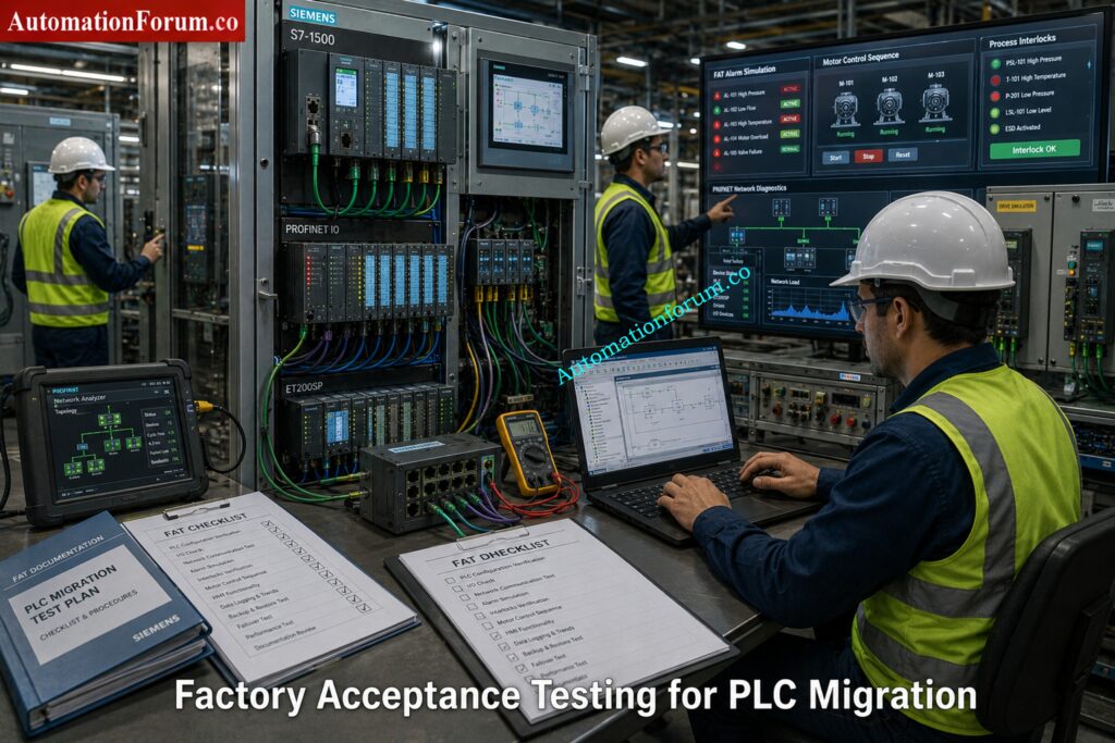
Practical problem:
Even when the PLC conversion succeeds, the plant may still stop if the HMI tags, alarms, or recipes do not align with the new controller structure.

Factory Acceptance Testing is the point where the migration is proven before the system reaches the plant floor.

FAT should simulate:

  • All key I/O operations
  • Alarm handling
  • Communication failures
  • Power recovery behavior
  • Startup and shutdown sequences
  • Interlocks and permissives
  • Drive commands
  • Redundancy or fallback logic
  • Operator actions

This is the stage where hidden logic problems are found while there is still time to fix them.

Best practice:
Do not limit FAT to “the machine starts.” Test abnormal conditions too. Many plants only discover logic weaknesses during alarms, power dips, or network drops.

Siemens S7 300 PLC Discontinued Migration Guide for Engineers - Perform Factory Acceptance Testing FAT

Site Acceptance Testing confirms that the migrated system works under real process conditions.

SAT should verify:

  • Actual field signals
  • Real network communication
  • Live instrument values
  • Motor starting sequences
  • Process interlocks
  • Safety responses
  • HMI operation
  • Alarm response time
  • Operator workflow

This is the last major checkpoint before the plant depends on the new system for production.

Practical warning:
SAT should not be treated as a formality. It is where commissioning differences between the test bench and the real plant often become visible.

NO vs NC Contact Confusion Ruining PLC Logic Designs: Understanding NO vs NC Contacts is key for Logic Writing in PLC Programming

Every migration project needs a clear rollback strategy.

That means knowing in advance:

  • What condition triggers rollback
  • How long rollback will take
  • Which backups will be used
  • Which cables or modules must be restored
  • Who authorizes the decision
  • How production restart will be managed

Without rollback planning, the plant is forced into a one way decision during commissioning. That is where downtime risk becomes dangerous.

Siemens’ guidance also emphasizes fallback strategy, sufficient time buffers, detailed planning, and testing before the point of no return.

Simple rule:
If the old system cannot be restored quickly, the cutover plan is incomplete.

Fastest Way to Troubleshoot PLC Permissive Logic Failures: PLC Permissive Logic Troubleshooting Procedure for Instrumentation Engineers

A strong execution order is usually:

  1. Audit the existing plant
  2. Backup every project and device
  3. Analyze communication and dependencies
  4. Map hardware replacements
  5. Convert software in a controlled way
  6. Migrate the HMI separately if needed
  7. Run FAT with failure scenarios included
  8. Execute SAT under real process conditions
  9. Cut over during a controlled shutdown window
  10. Keep rollback capability until stable operation is confirmed

Critical PLC Panel Inspection Checks Engineers Often Ignore: Running Inspection Checklist of PLC Components in Control Panels

Siemens S7 300 PLC Discontinued Migration Guide for Engineers - TIA Portal Migration Process for Siemens S7 300

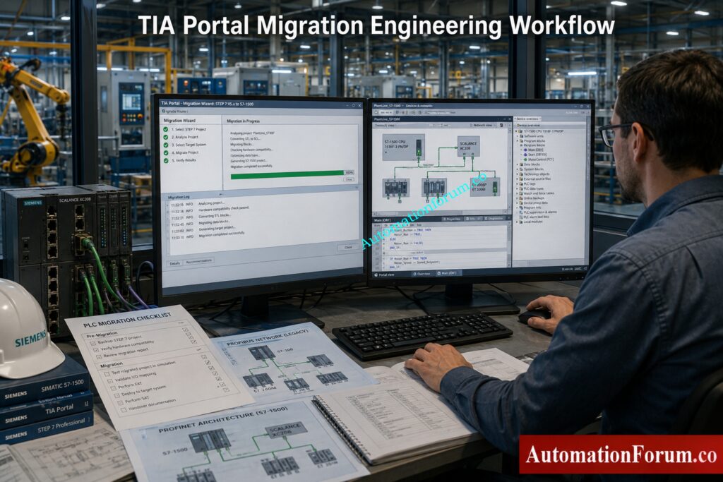
Migrating from STEP7 Classic to TIA Portal is one of the most critical phases in a Siemens PLC modernization project. On paper, the migration wizard looks simple. In real industrial environments, however, migration becomes a combination of software conversion, architecture redesign, hardware compatibility analysis, and commissioning risk management.

The Siemens migration guide explains that migration involves much more than opening an old project in TIA Portal. It includes project preparation, consistency checking, hardware inclusion, migration logs, compilation analysis, and correction of unsupported components.

For many plants, this is the first time the original PLC program has been deeply reviewed in years.

Why Hot Standby PLC Systems Prevent Costly Downtime: Hot Standby in PLC Systems: Architecture, Working, and Benefits

A structured migration workflow reduces engineering risk and helps avoid commissioning surprises.

A practical migration sequence usually includes:

  • Verify project consistency
  • Run readiness check
  • Open TIA Portal
  • Start migration wizard
  • Import STEP7 project
  • Review migration logs
  • Resolve unsupported components
  • Compile project
  • Correct errors
  • Test communication

The most important part is not the import itself. The most important part is understanding what changed after conversion.

Triconex vs Traditional PLCs: Safety Differences You Must Know: Difference Between Triconex PLC and Other PLCs: A Complete Guide

Before the migration can proceed, the original STEP7 project has to be cleaned and confirmed.

This includes:

  • Block consistency checking
  • Hardware diagnostics review
  • Symbol table validation
  • Communication verification
  • Alarm configuration review
  • Removal of obsolete objects
  • Backup of original archives

The migration method can result in inconsistencies if the original project has problems incomplete or unstable results.

Siemens specifically recommends consistency checking before migration because corrupted or partially modified projects may fail during conversion.

The Readiness Check Tool is one of the most important migration utilities in Siemens modernization projects.

It helps identify:

  • Unsupported hardware
  • Obsolete communication modules
  • Incompatible software blocks
  • Unsupported HMI objects
  • Safety conversion limitations
  • Legacy functions requiring manual correction

This stage often reveals hidden engineering problems that the plant team was unaware of.

A common example is discovering that the plant still depends on:

  • Old CP communication cards
  • Proprietary OPC drivers
  • Legacy WinCC Flexible objects
  • Unsupported GSD files
  • Third party PROFIBUS devices

Without this assessment, migration planning becomes incomplete.

Why Smart PLC Programmers Prefer RTO Over TON: Why is RTO Used in Place of TON Timer in PLC Program?

During migration, TIA Portal attempts to include the original hardware configuration inside the new project environment.

However, not all legacy devices have direct replacements.

This usually requires:

  • CPU replacement selection
  • Communication module replacement
  • Remote I/O migration planning
  • HMI replacement mapping
  • Network redesign

Many plants discover that the hardware migration itself is easier than adapting the communication structure around it.

For example:

  • MPI networks may disappear completely
  • PROFIBUS segments may migrate to PROFINET
  • ET200M may move to ET200SP
  • Old panels may require complete redesign

This is why migration projects should always be treated as system modernization projects rather than simple PLC upgrades.

One of the most overlooked engineering tasks is analyzing migration logs properly.

TIA Portal generates logs that identify:

  • Unsupported instructions
  • Replaced functions
  • Addressing conflicts
  • Missing drivers
  • Obsolete hardware references
  • Failed conversions

Experienced engineers spend significant time reviewing these logs before testing begins.

Ignoring migration warnings is one of the fastest ways to create commissioning problems later.

Dangerous Rockwell PLC Vulnerability Every Engineer Must Address: Critical Flaw in Rockwell ControlLogix CVE-2024-6242 – Trusted Slot Bypass Vulnerability

Same PC Migration

Same PC migration is possible when:

  • STEP7 Classic and TIA Portal coexist
  • Licensing is compatible
  • Required drivers are available
  • Windows compatibility is maintained

This approach is faster in smaller projects.

However, many industrial sites avoid this method because older STEP7 environments often depend on:

  • Windows XP
  • Legacy USB drivers
  • Old MPI interfaces
  • Unsupported licensing systems

Mixing old and new engineering software on the same machine sometimes creates instability.

Different PC Migration

Many engineers prefer using separate engineering systems for migration.

In practice, this usually means:

  • One legacy engineering station for STEP7 Classic
  • One modern engineering station for TIA Portal
  • Separate backup environments
  • Virtual machine support for legacy access

This reduces the risk of damaging the original project environment.

It also gives the engineering team a rollback option if conversion problems occur.

In many real plants, the old engineering laptop becomes a protected recovery system during the entire migration project.

Most migration failures are not caused by hardware replacement.

They are caused by hidden software assumptions inside legacy automation systems.

These issues usually remain invisible until commissioning begins.

Older STEP7 projects often rely heavily on:

  • M memory
  • Absolute DB addressing
  • Pointer based logic
  • Direct byte manipulation

These methods worked well in older architectures but become difficult to maintain in modern symbolic programming environments.

When migrating to S7 1500, symbolic programming becomes extremely important because optimized blocks behave differently from traditional absolute addressing structures.

Common Real World Problem

An old batching system may use:

  • DB100.DBW12
  • M250.0
  • Pointer indirect access

across hundreds of functions.

After migration, troubleshooting becomes extremely difficult because the original memory relationships no longer behave exactly the same way.

Many engineering teams eventually choose partial code rewriting instead of carrying forward legacy addressing structures forever.

Prevent PLC I/O Failures Before They Shut Down Plants: Proactive Maintenance Strategies for PLC I/O Modules: Reduce Downtime & Improve Reliability

Large industrial plants often contain extensive STL or AWL programming developed over decades.

These sections may include:

  • Indirect addressing
  • Jump logic
  • Pointer arithmetic
  • Custom communication handling
  • Complex sequencing

While some STL logic can migrate, maintaining large STL based projects inside modern TIA Portal environments becomes increasingly difficult.

That is why many modernization projects gradually convert critical logic into:

  • SCL
  • Structured modular blocks
  • Library based functions

Why Engineers Move Toward SCL

SCL improves:

  • Readability
  • Diagnostics
  • Scalability
  • Long term maintainability
  • Team collaboration

Younger engineers are also far more comfortable supporting structured code compared with heavily compressed STL logic.

Siemens S7 300 PLC Discontinued Migration Guide for Engineers - PROFIBUS to PROFINET Migration Challenges

This is one of the biggest hidden engineering risks in modernization projects.

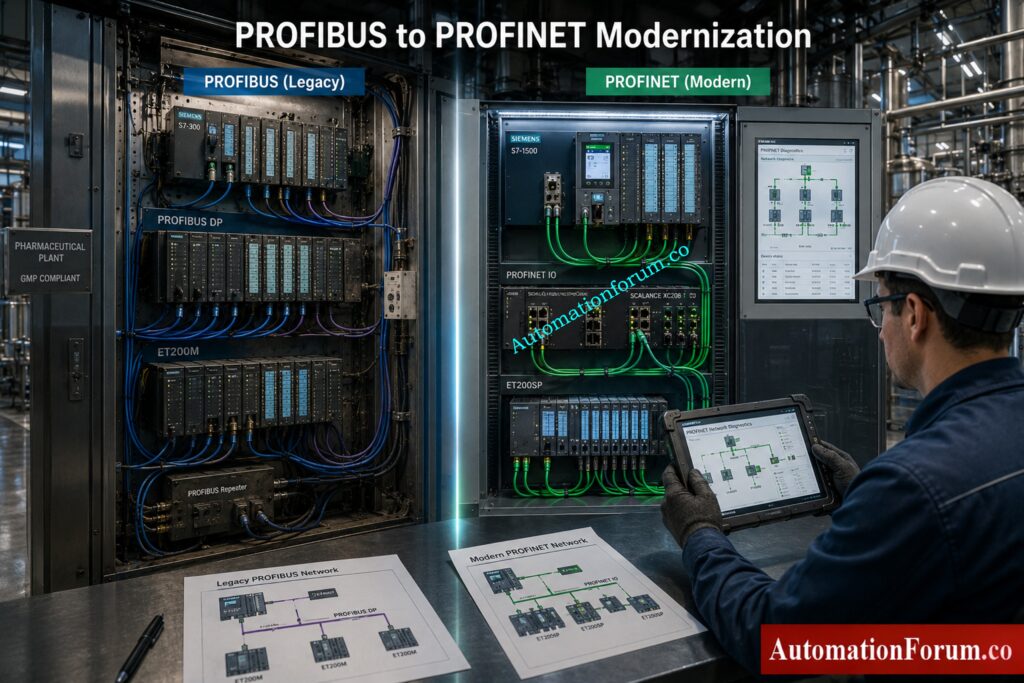
At first glance, replacing PROFIBUS with PROFINET seems simple.

In reality, engineers often encounter:

  • Device naming conflicts
  • IP addressing problems
  • Network timing changes
  • Communication latency differences
  • Switch configuration issues
  • VFD communication instability

The behavior of PROFIBUS systems was serial and deterministic. PROFINET introduces Ethernet based communication with different network behavior and infrastructure requirements.

Common Field Failure

A plant may successfully start motors during FAT testing, but experience intermittent communication drops during full production load because switch configuration or network segmentation was not properly designed.

Boost PLC Performance Using These Proven Optimization Techniques: How to Increase PLC Speed: 7 Optimization Tips + Advanced Programming Guide

Older HMIs often depend on communication methods that are no longer standard.

These may include:

  • MPI
  • PROFIBUS
  • Proprietary drivers
  • Old panel firmware

Migration frequently causes:

  • Alarm failures
  • Recipe corruption
  • Screen navigation problems
  • Communication timeout issues
  • Historical data mismatch

Many engineers underestimate how tightly older HMIs are connected to the original PLC memory structure.

Once symbolic addressing changes, the HMI often requires extensive rework.

One hidden problem in S7 1500 migration is CPU execution speed.

S7 1500 processors execute logic much faster than older S7 300 CPUs.

That sounds beneficial, but it can unexpectedly affect:

  • Pulse timing
  • Counter operation
  • PID loop stability
  • Conveyor sequencing
  • Start and stop synchronization

Real Industrial Example

An old machine may rely on scan cycle timing assumptions created 15 years ago.

After migration, outputs react faster and sequencing overlaps begin appearing intermittently.

This creates startup failures that are difficult to reproduce during testing.

Third party systems are often the most dangerous part of a migration project.

Examples include:

  • Modbus gateways
  • Barcode systems
  • OPC servers
  • Energy meters
  • Packaging machines
  • Weighing systems

Many older drivers were written specifically for:

  • STEP7 Classic
  • Windows XP
  • Old communication libraries

During modernization, these systems may fail completely or require expensive replacement.

Most Widely Used PLC Brands in Industrial Automation Today: Which PLC is Mostly used in the Automation Industry?

Yes, some S7 300 repair options and spare parts support may still be available depending on the module type and region.
For industrial automation upgrade planning, engineers should not depend only on repair and should prepare a migration strategy.

Yes, STEP 7 to TIA Portal migration is possible using the migration wizard and readiness check tools.
To migrate smoothly from a Siemens S7 300 to a S7 1500, begin by verifying project consistency and hardware compatibility.

Review or conversion of legacy code is typically necessary due to restricted STL support in S7 1500 compared to STEP7 Classic.

For Siemens TIA Portal migration the translation to symbolic programming and SCL conversion is preferred in general for improved maintainability.

Yes, ET200M can sometimes be re-used during a phased S7 300 migration, depending on the plant design and the CPU target.
For long term ET200M replacement, ET200SP or ET200MP is usually a better choice in PLC modernization projects.

WinCC Flexible support is now limited, and many plants are moving to WinCC migration in TIA Portal.
For long term HMI modernization, Comfort Panels and Unified Panels are the better future proof option.

PLC Ladder Logic Rules Every Programmer Must Follow: Top 6 Important Rules for PLC Ladder Diagram Programming

Yes, existing field wiring can often be reused in a Siemens S7 300 to S7 1500 migration if the cabinet design allows it.
A proper hardware mapping study is needed before ET200M replacement or HMI migration begins.

The biggest PLC migration risk is unexpected downtime due by insufficient testing, missing backups or concealed communication problems.

A good FAT and SAT plan is crucial for safe execution of the industrial automation upgrade.

Migration time is a function of plant size, architecture complexity, scope of safety and amount of HMI or SCADA work needed.

A modest S7 300 transfer might be rapid, but a full TIA Portal migration from PROFIBUS to PROFINET will take significantly longer.

S7 1200 Ideal for tiny stand-alone systems and simple OEM automation applications.

For bigger Siemens PLC upgrade projects, S7 1500 is usually the preferred target because of performance and diagnostics.

S7 1500 is selected for higher performance, enhanced diagnostics, cyber security and good long term support.

It is the greatest solution for future proof automation, Industry 4.0 preparedness and current TIA Portal migration plans.

Migration of a Safety PLC must be approached cautiously, as validation, SIL standards, and safety testing are needed.
Direct conversion is not enough, so every safety system should be tested, documented, and approved before cutover.

Absolutely, every Siemens S7 300 migration should include cybersecurity upgrades as part of PLC lifecycle management.
Modern S7 1500 systems support stronger security, better access control, and safer industrial automation connectivity.

Allen Bradley PLC Datasheet Reading Made Extremely Simple: How to Read the PLC Datasheet: Allen-Bradley 1762 Model Step-by-Step Guide

The Siemens S7 300 platform transformed industrial automation and continues running critical infrastructure worldwide.

But the industrial landscape has changed.

Plants now face:

  • Spare part shortages
  • Cybersecurity pressure
  • Aging networks
  • Unsupported software
  • Rising downtime risk

Migration is no longer just a hardware upgrade.

It is a strategic modernization project that impacts:

  • Reliability
  • Productivity
  • Cybersecurity
  • Maintainability
  • Future scalability

The most successful migration projects are not the fastest projects.

They are the best planned projects.

A properly engineered S7 300 to S7 1500 migration can deliver:

For automation engineers, system integrators, and modernization teams, the time to plan migration is now before the next unexpected failure becomes a production disaster.


Advanced Safety Instrumented System (SIS) Inspection Checklist for IEC 61511 Compliance

0
Advanced Safety Instrumented System (SIS) Inspection Checklist for IEC 61511 Compliance
Table of Contents

A Safety Instrumented System (SIS) is one of the most critical protection layers in any process plant. Its job is simple in principle but extremely important in practice: detect unsafe process conditions and move the plant to a safe state before those conditions turn into an accident. 

In real industrial environments, that safe state may mean shutting down equipment, isolating a process line, stopping a compressor, closing a valve, or triggering an emergency action that protects people, assets, and the environment.

You will find SIS applications across oil and gas, refineries, petrochemical plants, LNG facilities, power plants, chemical industries, pharmaceutical units, and water treatment plants. In all these industries, the SIS works as an independent layer of protection, designed to act when the normal control system is no longer enough.

Unlock the complete IEC 61511 SIS engineering guide today: S84 / IEC 61511 Standard for Safety Instrumented Systems – Complete Guide

A Safety Instrumented Function (SIF) is the specific safety action inside the SIS. In most cases, a SIF is built from three main parts:

  • Sensor(s)
  • Logic solver
  • Final control element
  • For example, in a high-pressure shutdown loop, a pressure transmitter detects the unsafe condition, a safety PLC processes the logic, and an ESD valve isolates the process. 
  • That is why SIS health cannot be checked only during shutdown or turnaround. It must be watched continuously while the plant is running.

Test your practical SIS expertise with this advanced safety quiz: Test Your Expertise in Safety Instrumented Systems (SIS): Knowledge Quiz

  • A proper SIS running inspection checklist helps plant teams catch hidden failures, bypass issues, unhealthy diagnostics, valve problems, and unsafe temporary changes before they become serious safety incidents. 
  • It also supports SIL integrity, proof testing, lifecycle documentation, audit readiness, and compliance with IEC 61511 and ISA 84.
  • In many plants, the real danger is not a complete SIS failure that is obvious and easy to spot. 
  • The real danger is a hidden weakness that stays unnoticed for weeks or months such as a stuck solenoid, a drifting transmitter, a valve that no longer strokes correctly, a redundancy mismatch, a communication fault, or an unauthorized bypass. This is exactly why a strong running inspection routine is so valuable.

Avoid these dangerous SIS design mistakes before project commissioning: Top Critical Mistakes in Safety Instrumented System Design as per ISA 84 Standard and How to Avoid Them 

The main purpose of SIS running inspection is to ensure that every safety instrumented function remains healthy, available, and ready to respond when required.


Prepare confidently for SIS interviews with these expert questions:Safety Instrumented System(SIS) Interview Questions and Answers

Running inspection helps identify failures that may not be visible during normal operation, including:

  • Sensor drift
  • Solenoid coil degradation
  • Stuck shutdown valves
  • Faulty relay contacts
  • Communication failure in the logic solver

These problems may stay hidden until a real demand occurs, which is exactly when the plant needs the SIS most.

A healthy SIS helps prevent:

  • Fire
  • Explosion
  • Toxic gas release
  • Environmental contamination
  • Major equipment damage

False trips create production loss, upset plant operation, and can even damage equipment. Inspection helps identify causes such as:

  • Signal noise
  • Ground loops
  • Intermittent wiring faults
  • Poor power quality
  • Weak bypass control

Inspection confirms that critical elements can still perform their duty, such as:

  • ESD valves moving freely
  • Solenoids energizing and de-energizing correctly
  • Safety PLC redundancy staying healthy
  • Field instruments remaining within calibration limits

Learn how SIS voting logic works in industrial applications: Voting Logic in Safety Instrumented System

Running inspection supports:

  • IEC 61511 compliance
  • Functional safety audits
  • SIL verification
  • Proof test planning
  • Maintenance record keeping

A disciplined SIS inspection program reduces nuisance shutdowns while keeping the safety layer effective.

Understand SIS basics every instrumentation engineer must clearly know: SIS (safety instrumented system) basics

Advanced SIS Running Inspection Checklist
SIS General Health Monitoring Checklist
Sl NoInspection AreaEquipment / TagInspection RequirementExpected ConditionInspection MethodFrequency
1SIS ControllerSafety PLCController healthy statusHealthy without faultHMI diagnosticsDaily
2CPU RedundancyRedundant CPURedundant synchronizationBoth CPUs synchronizedPLC diagnosticsDaily
3Power SupplySIS Power ModuleVoltage monitoringStable DC voltageMultimeter / HMIDaily
4CommunicationSafety NetworkCommunication integrityNo communication lossDiagnostic screenDaily
5SOE SystemEvent RecorderTime synchronizationAccurate timestampSOE checkWeekly
6DiagnosticsSIS AlarmsDiagnostic alarm reviewNo critical alarmsAlarm reviewDaily
7Memory UtilizationPLC MemoryMemory load verificationWithin safe limitEngineering stationMonthly
8RedundancyCPU SwitchoverSwitchover readinessSuccessful redundancyDiagnostic reviewMonthly
9Application IntegritySafety LogicChecksum verificationMatching checksumEngineering softwareMonthly
10CybersecuritySIS AccessUnauthorized access checkNo unauthorized loginAudit logsWeekly

Discover how safety light curtains protect industrial working environments: Safety Light Curtain Working Principle: How Does a Safety Light Curtain Work?

Sl NoInspection AreaEquipment / TagInspection RequirementExpected ConditionInspection MethodFrequency
11CPU DiagnosticsSafety PLC CPUCPU fault monitoringNo active faultHMI diagnosticsDaily
12Scan TimeLogic SolverScan time verificationWithin design limitDiagnostic toolsWeekly
13CommunicationRedundant EthernetCommunication redundancyHealthy redundancySwitch diagnosticsWeekly
14Logic ValidationSafety ProgramLogic mismatch verificationNo mismatchCompare toolMonthly
15Fault LEDsPLC RackLED fault inspectionNo red LEDsVisual inspectionDaily
16Bypass MonitoringSafety LogicActive bypass checkNo unauthorized bypassBypass reportDaily
17Forced I/OSafety PLCForced signal verificationNo active forceEngineering stationDaily
18FirmwarePLC FirmwareFirmware verificationApproved versionSoftware checkQuarterly
19Online EditsSIS LogicUnauthorized online edit checkNo unauthorized changesAudit reviewWeekly
20Battery HealthCPU BatteryBattery voltage checkHealthy batteryDiagnosticsMonthly

Simplify intrinsic safety loop calculations using this engineering calculator: IS Barrier Earth Fault Current Calculator | Intrinsic Safety Loop Design Tool

 SIS Field Instrument Inspection Checklist
Sl NoInspection AreaEquipment / TagInspection RequirementExpected ConditionInspection MethodFrequency
21Pressure TransmitterPT-101Calibration statusWithin calibration validityCalibration recordMonthly
22Temperature TransmitterTT-101Sensor drift checkStable readingTrend analysisMonthly
23Flow TransmitterFT-201Impulse line leakageNo leakageVisual inspectionWeekly
24Level TransmitterLT-301Diagnostic healthHealthy diagnosticsHART communicatorWeekly
25Gas DetectorGD-101Sensor poisoning checkNormal sensor responseGas bump testMonthly
26Flame DetectorFD-201Optical cleanlinessLens cleanVisual inspectionWeekly
27Vibration SwitchVS-101Mechanical integritySecure mountingPhysical checkMonthly
28ESD Push ButtonPB-ESD-01Functional verificationOperable conditionFunctional testMonthly
29Limit SwitchLSH-101Switching integrityProper operationSimulation testQuarterly
30Junction BoxJB-SIS-01Water ingress checkDry and sealedVisual inspectionMonthly

Challenge your ESD system knowledge with this practical industry quiz: ESD Control System Basics Quiz for Process Industries

Final Element Inspection Checklist
Sl NoInspection AreaEquipment / TagInspection RequirementExpected ConditionInspection MethodFrequency
31Shutdown ValveXV-101Partial stroke testingSmooth movementPST systemMonthly
32ESD ValveSDV-201Leakage verificationNo passing leakageLeak testQuarterly
33Solenoid ValveSOV-101Coil resistance checkNormal resistanceMultimeterMonthly
34MOVMOV-401Position feedbackAccurate indicationFunctional testMonthly
35Pneumatic SupplyAir HeaderAir pressure monitoringStable pressurePressure gaugeDaily
36Valve StrokeSDV-202Stroke timingWithin design limitStroke timerQuarterly
37Fail Safe ActionShutdown ValveFail-safe verificationCorrect fail positionFunctional testShutdown
38Mechanical IntegrityValve AssemblyObstruction checkNo obstructionVisual inspectionMonthly
39Positioner FeedbackValve PositionerSignal responseStable responseLoop testQuarterly
40Bypass ValveManual BypassPosition verificationClosed and lockedVisual inspectionDaily

Master hazardous area installation rules using IEC 60079-14 guide: IEC 60079-14 Explained: Complete Guide to Hazardous Area Installation for Instrumentation and Control Systems

SIS Alarm and Bypass Management Checklist
Sl NoInspection AreaEquipment / TagInspection RequirementExpected ConditionInspection MethodFrequency
41Bypass MonitoringSIS BypassActive bypass reviewAuthorized onlyBypass log reviewDaily
42Override ManagementTemporary OverrideTimeout verificationWithin approved limitOverride reportDaily
43Alarm ManagementAlarm SystemAlarm shelving reviewNo stale shelvingAlarm reviewDaily
44Alarm FloodOperator StationAlarm flood analysisControlled alarm rateAlarm analyticsWeekly
45Key ControlBypass KeyKey management verificationControlled accessAudit checkWeekly

Learn redundant transmitter logic and SIL concepts with examples: Redundant Transmitters Explained: Reliability, Voting Logic and SIL for Instrumentation Engineers

SIS UPS and Power Supply Inspection Checklist
Sl NoInspection AreaEquipment / TagInspection RequirementExpected ConditionInspection MethodFrequency
46UPS HealthUPS PanelUPS status monitoringHealthy operationHMI / UPS panelDaily
47Battery VoltageUPS BatteryBattery conditionStable voltageBattery testerMonthly
48Charger HealthCharger UnitCharger verificationNormal chargingIndicator checkWeekly
49EarthingSIS PanelEarthing continuityLow resistanceEarth testerQuarterly
50Panel TemperatureSIS CabinetTemperature monitoringNormal temperatureThermal scannerWeekly

Understand practical differences between ESD and SIS safety systems: ESD vs SIS Difference When to Use Each and Practical Engineering Guide

Sl NoInspection AreaEquipment / TagInspection RequirementExpected ConditionInspection MethodFrequency
51Safety NetworkSIS EthernetCommunication stabilityNo packet lossDiagnosticsWeekly
52Fiber LinkFiber NetworkFiber health verificationHealthy linkOTDR / diagnosticsQuarterly
53Switch HealthNetwork SwitchPort diagnosticsNo failed portsSwitch monitoringWeekly
54FirewallSIS FirewallSecurity monitoringNo unauthorized eventSecurity logsWeekly
55Network LatencySIS CommunicationLatency monitoringWithin limitMonitoring softwareMonthly

Confused about SIS, SIF and SIL? Start learning here: What is SIS, SIF and SIL? An In-Depth Guide to Functional Safety in Process Industries

Sl NoInspection AreaEquipment / TagInspection RequirementExpected ConditionInspection MethodFrequency
56Panel CleanlinessSIS CabinetDust inspectionClean conditionVisual inspectionWeekly
57Cooling FanPanel FanFan operationProper airflowPhysical inspectionMonthly
58HVACInstrument RoomHVAC conditionStable temperatureHVAC checkWeekly
59Water IngressPanel DoorSeal inspectionNo ingressVisual inspectionMonthly
60CorrosionTerminal BlocksCorrosion inspectionNo corrosionVisual inspectionQuarterly

Simplify SIL verification and PFDavg calculations with practical methods: SIF PFDavg / SIL Verification – Complete Guide + Online Calculator (IEC 61508 / 61511)

Sl NoInspection AreaEquipment / TagInspection RequirementExpected ConditionInspection MethodFrequency
61SIL RecordsSIS DocumentationSIL verification reviewUpdated recordsDocument auditQuarterly
62Proof TestSIF LoopProof test due reviewNo overdue testsMaintenance recordsMonthly
63Cause and EffectShutdown MatrixLogic validationAccurate sequenceReview / testQuarterly
64SRSSafety Requirement SpecSRS availabilityApproved copy availableDocument reviewQuarterly
65Lifecycle DocumentsSIS SystemDocumentation completenessUpdated lifecycle recordsAuditAnnual

Learn IEC testing and repair deferral best practices for safety: Testing and Repair Deferral – IEC Guidelines, Procedure, and Best Practices

Sl NoInspection AreaEquipment / TagInspection RequirementExpected ConditionInspection MethodFrequency
66Bypass LogbookShift RecordsLogbook reviewUpdated entriesDocument reviewDaily
67Shift HandoverOperationsSafety communicationComplete communicationInterview / reviewDaily
68Operator AwarenessOperations TeamSIS awareness checkAdequate knowledgeInterviewMonthly
69PTW ComplianceMaintenance WorkPermit verificationProper permit usageAuditWeekly
70Emergency PreparednessOperations TeamEmergency readinessPrepared personnelDrill reviewQuarterly

Download important functional safety terms used in industrial automation: Functional Safety Terminology – Excel Download for Industrial Automation

AbnormalityProbable CauseRecommended Action
Frequent false tripsGround loop or signal noiseVerify shielding and grounding
Valve sluggish movementCorrosion or air leakagePerform maintenance and PST
Sensor driftAging transmitter sensorRecalibrate or replace sensor
CPU redundancy mismatchFirmware inconsistencySynchronize firmware
Water ingress in JBFailed gland sealingReplace cable gland
Gas detector unstableSensor poisoningReplace sensing element
High panel temperatureHVAC failureRestore cooling immediately
Communication alarmFiber issueInspect switch and fiber link

Discover how emergency block valves protect critical process industries: What is an Emergency Block valve and How does it work

IssueSymptomRoot CauseImpactCorrective Action
Spurious TripsUnexpected shutdownNoise or grounding issueProduction lossImprove grounding
Solenoid FailureValve not actuatingCoil burnoutFailed shutdownReplace solenoid
Valve StickingDelayed responseCorrosionUnsafe shutdown delayLubrication / maintenance
Sensor DriftIncorrect readingAging sensorUnsafe process operationCalibration
Communication FailureLoss of signalNetwork issueSIS unavailableRestore communication
CPU MismatchRedundancy alarmSync failureReduced availabilityCPU synchronization
Power FluctuationSystem rebootUPS instabilitySIS interruptionUPS maintenance
Ground LoopSignal fluctuationPoor groundingFalse tripImprove earthing
Water IngressCorrosionFailed sealingEquipment damageReplace seals
Gas Detector PoisoningSlow responseSensor contaminationGas leak undetectedSensor replacement
Inspection ActivityRecommended Frequency
Critical alarm reviewDaily
Bypass verificationDaily
CPU diagnostics reviewDaily
UPS inspectionWeekly
Sensor diagnostics reviewWeekly
Valve partial stroke testMonthly
Proof test reviewMonthly
Network diagnosticsMonthly
SIL verification reviewQuarterly
Full functional testAnnual
Shutdown inspectionDuring turnaround

Learn how HIPPS systems prevent dangerous process overpressure conditions: How does the HIPPS system work in the Oil and gas Industry?

Advanced SIS Inspection Checklist Excel Workbook

Professional and fully editable Safety Instrumented System (SIS) running inspection checklist workbook designed for IEC 61511 compliance, plant audits, shutdown reliability, safety PLC monitoring, field instrument inspection, and functional safety management. Includes dashboard, master checklist, section-wise inspection tabs, corrective action tracking, filters, dropdowns, conditional formatting, and due-date monitoring. 

  • Maintain complete functional safety lifecycle documentation.
  • Ensure all proof tests are traceable.
  • Avoid unauthorized bypass activation.
  • Implement strict Management of Change (MOC).
  • Review cause and effect matrices regularly.
  • Maintain spare solenoids, relays, and transmitters.
  • Conduct regular functional safety audits.
  • Use cybersecurity monitoring for SIS networks.
  • Train operators on alarm response procedures.
  • Minimize nuisance shutdowns through proper maintenance.
  • Verify all bypasses before startup.
  • Perform stroke testing after maintenance.
  • Confirm transmitter impulse lines are free from blockage.
  • Validate fail-safe action after shutdown work.
  • Review all temporary modifications before startup.
Why Regular SIS Inspection Is Essential for Industrial Safety

A reliable Safety Instrumented System is one of the most important protective barriers in any modern industrial facility. Its performance depends not only on good engineering design but also on disciplined inspection, proof testing, maintenance, and lifecycle management.

Periodic SIS running inspection plays a major role in maintaining SIL integrity, detecting hidden dangerous failures, preventing nuisance trips, and ensuring that safety functions respond properly when a real emergency happens. Many serious industrial incidents can be traced back to bypassed protections, neglected shutdown valves, failed sensors, weak maintenance practices, or unauthorized system changes.

A strong functional safety culture requires close coordination between operations, maintenance, instrumentation, engineering, and management. The SIS long-term reliability depends on proper bypass management, correct documentation, alert management, cybersecurity awareness and disciplined MOC practices.

IEC 61511, for example, is quite explicit that functional safety is a lifecycle duty rather than a project that you do once. 

That means inspection routines, audits, proof testing, and competency development must remain active throughout the plant’s operating life.

A disciplined Safety Instrumented System inspection program helps industries maintain functional safety compliance, reduce operational risk, prevent dangerous hidden failures, and improve shutdown reliability throughout the entire SIS lifecycle

Learn essential shutdown signals used for emergency valve protection: Signals for Emergency Valve Shutdown in Critical Processes

Instrumentation Designer Interview Questions and Answers for EPC Projects

0
Instrumentation Designer Interview Questions and Answers for EPC Projects

Instrumentation design is one of the most important disciplines in EPC projects because it directly affects plant safety, reliability, operability, and maintenance. Instrumentation designers are responsible for converting engineering concepts into practical installation drawings and construction deliverables used in Oil and Gas, Petrochemical, Refinery, LNG, Power Plant, Chemical, and Process Industries.

This complete guide covers the most important Instrumentation Designer Interview Questions and Answers used by EPC companies such as Technip, Fluor, Bechtel, Petrofac, Worley, L&T, and Saipem.

The content includes practical engineering explanations, EPC workflow knowledge, field installation practices, SPI and SP3D concepts, cable tray routing, hook up drawings, hazardous area design, and real project coordination practices.

What Are the Key Responsibilities of an Instrumentation Designer?

Main responsibilities include:

  • Preparing instrument location layouts
  • Developing hook-up drawings for field instruments
  • Preparing loop diagrams and wiring drawings
  • Designing cable tray routing and cable layouts
  • Preparing junction box layouts and cable schedules
  • Supporting 3D modeling activities
  • Coordinating with process, piping, electrical, and civil departments
  • Reviewing vendor drawings and technical documents
  • Assisting site teams during installation and commissioning
  • Ensuring compliance with project standards and safety requirements

Instrumentation designers also ensure that all drawings are accurate, practical, and suitable for field installation.

Instrumentation Designer Interview Questions and Answers for EPC Projects - What Is the Complete Workflow of Instrumentation Design?

What Is the Complete Workflow of Instrumentation Design?

The instrumentation design workflow starts from understanding process requirements and ends with commissioning support and final as-built documentation.

Typical instrumentation design workflow:

1. Review Basic Engineering Inputs

2. Prepare Engineering Documents

  • Instrument Index
  • Instrument Datasheets
  • I/O List
  • Control Philosophy
  • Cause & Effect Matrix

3. Perform Detailed Engineering

  • Prepare hook-up drawings
  • Develop loop diagrams
  • Prepare cable schedules and JB schedules
  • Design instrument layouts and cable tray routing

4. Coordinate with Other Departments

  • Coordinate with piping for process connections
  • Coordinate with electrical for power requirements
  • Coordinate with civil and structural teams for supports

5. Perform 3D Modeling and Review

  • Verify accessibility and maintenance space
  • Perform clash checking
  • Optimize cable routing and instrument locations

6. Procurement and Vendor Coordination

  • Review vendor drawings
  • Verify compatibility with project specifications

7. Construction and Commissioning Support

  • Resolve site technical queries
  • Support loop checking and testing
  • Assist during FAT and SAT
  • Update as-built drawings after commissioning

This workflow ensures smooth project execution from engineering to plant startup.

What Are the Major Deliverables in Instrumentation Engineering?

Instrumentation engineering produces several documents and drawings required for design, procurement, installation, testing, and commissioning activities.

Major instrumentation deliverables include:

Engineering Deliverables

  • Instrument Index
  • Instrument Datasheets
  • I/O List
  • Control Philosophy
  • Alarm and Trip List
  • Cause & Effect Matrix

Installation Deliverables

  • Instrument Hook-up Drawings
  • Instrument Location Layouts
  • Cable Tray Layouts
  • Junction Box Layouts
  • Air Header Layouts
  • Instrument Support Drawings

Wiring and Cable Deliverables

  • Loop Diagrams
  • Cable Schedules
  • JB Schedules
  • Interconnection Diagrams
  • Wiring Drawings

Control System Deliverables

  • PLC/DCS Architecture Drawings
  • Logic Diagrams
  • HMI Graphics Documents

Construction and Commissioning Deliverables

  • Material Take-Off (MTO)
  • Red Markup Drawings
  • As-built Drawings
  • Loop Test Reports

These deliverables are essential for engineering, construction, operation, and maintenance of the plant.

What Is the Difference Between an Instrument Engineer and an Instrument Designer?

Instrument Engineers and Instrument Designers work together, but their responsibilities are different.

Instrument EngineerInstrument Designer
Performs engineering calculationsPrepares detailed drawings
Selects instruments and valvesDevelops layouts and routing
Creates technical specificationsCreates installation details
Handles control philosophyHandles CAD drafting
Reviews vendor technical documentsPrepares construction drawings
Performs sizing calculationsDevelops hook-up drawings
Responsible for engineering decisionsResponsible for drawing accuracy
Focuses on system performanceFocuses on practical installation

Simple explanation:

  • Instrument Engineer decides what should be used
  • Instrument Designer decides how and where it should be installed

Both roles are important for successful project execution.

Which Standards Are Followed in Instrumentation Design?

Instrumentation design follows international standards to ensure safety, reliability, compatibility, and proper engineering practices.

Commonly used standards are:

ISA Standards

  • ISA 5.1 → Instrument symbols and identification
  • ISA 84 → Safety Instrumented Systems
  • ISA 18.2 → Alarm Management

IEC Standards

  • IEC 61511 → Functional Safety
  • IEC 60079 → Hazardous Area Classification
  • IEC 61131 → PLC Systems

Other International Standards

  • API Standards
  • ANSI Standards
  • NFPA Standards
  • IEEE Standards
  • ISO Standards
  • NEMA Standards

Additional project requirements:

  • Client standards
  • Company engineering standards
  • Local electrical regulations
  • Plant safety standards

Following standards ensures safe and reliable plant operation and reduces engineering errors.

Which Documents Are Received from the Process Department?

The process department provides several important input documents required for instrumentation engineering and design activities.

Main documents received from process department are:

Importance of these documents:

These documents help instrumentation engineers:

  • Select suitable instruments
  • Develop control strategies
  • Understand process conditions
  • Design safe and reliable systems

Instrumentation design cannot start properly without process department inputs.

Instrumentation Designer Interview Questions and Answers for EPC Projects - How Do You Read and Interpret P&IDsin Instrumentation Engineering?

How Do You Read and Interpret P&IDs in Instrumentation Engineering?

P&IDs are the most important drawings in instrumentation engineering because they show the complete process flow, instruments, piping systems, and control loops used in the plant.

Steps to read and interpret a P&ID:

1. Understand Process Flow

  • Identify flow direction
  • Study process sequence
  • Understand plant operation

2. Identify Major Equipment

  • Pumps
  • Tanks
  • Vessels
  • Heat exchangers
  • Compressors

3. Study Instrument Symbols and Tags

Examples:

  • PT → Pressure Transmitter
  • LT → Level Transmitter
  • TIC → Temperature Indicating Controller
  • FV → Flow Valve

4. Understand Control Loops

Check:

  • Measuring instrument
  • Controller
  • Final control element

5. Identify Signal Types

  • Pneumatic signals
  • Electrical signals
  • Digital communication signals

6. Review Safety Systems

  • Shutdown valves
  • Trips and interlocks
  • Alarm systems
  • Emergency shutdown systems

P&IDs are used as the base document for almost all instrumentation engineering activities.

What Checks Should Be Done Before Starting Instrumentation Design?

Before starting instrumentation design, several technical, safety, and engineering checks are performed to avoid future problems during installation and commissioning.

Main checks include:

Document Verification

  • Verify latest P&ID revision
  • Check approved specifications
  • Review vendor documents

Technical Checks

  • Verify instrument accessibility
  • Check utility availability
  • Review hazardous area classification
  • Check process conditions and operating parameters

Layout Checks

  • Verify equipment locations
  • Check maintenance clearance
  • Confirm support availability
  • Review cable routing feasibility

Interdisciplinary Coordination

  • Coordinate with piping department
  • Coordinate with electrical department
  • Coordinate with civil and structural teams

Additional Checks

  • Verify communication protocols
  • Check spare philosophy
  • Review control room capacity
  • Check existing plant constraints in brownfield projects

These checks help reduce rework and improve project quality.

Which Software and Tools Are Used by Instrumentation Designers?

Instrumentation designers use different software tools for drafting, database management, modeling, and control system engineering.

Commonly used software includes:

Drafting and Design Software

  • AutoCAD
  • MicroStation
  • E3D
  • SP3D

Instrumentation Engineering Software

  • SPI (SmartPlant Instrumentation)
  • AVEVA Instrumentation
  • COMOS

3D Review and Clash Detection Tools

  • Navisworks
  • SmartPlant Review

Control System Software

  • Siemens PCS7
  • Allen Bradley Studio 5000
  • Emerson DeltaV
  • Yokogawa CENTUM VP

Engineering Utilities

  • Microsoft Excel
  • Conval
  • Loop calculation tools

Communication and Calibration Tools

  • HART Communicator
  • Modbus configuration tools
  • Profibus tools

Knowledge of both engineering software and drafting tools is important for instrumentation design activities.

Which Projects Have You Worked On and What Was Your Role?

Sample Interview Answer:

I was responsible for preparing:

  • Instrument location layouts
  • Hook-up drawings
  • Loop diagrams
  • Cable schedules
  • Junction box layouts
  • Cable tray routing drawings

I also coordinated with process, piping, electrical, and civil departments to ensure proper installation and routing activities. In addition, I participated in 3D model reviews, vendor drawing reviews, and site support activities during construction and commissioning phases.

I have experience working with software such as SPI, AutoCAD, SP3D, and Navisworks for instrumentation engineering and design activities.”

Crush protocol interviews with these high-value answer strategies: Industrial Communication Protocol Interview Questions and Answers

What Factors Should Be Considered While Locating Field Instruments?

While locating field instruments, several operational, safety, and maintenance factors must be considered to ensure proper performance and easy accessibility.

Main factors considered are:

  • Accessibility for operation and maintenance
  • Visibility from operating area
  • Safety of personnel
  • Distance from process tapping point
  • Vibration and temperature effects
  • Hazardous area classification
  • Availability of supports and structures
  • Cable routing feasibility
  • Ease of calibration and removal
  • Protection from weather conditions

Instruments should be installed in locations where technicians can easily inspect, calibrate, and maintain them without disturbing plant operation. Proper instrument location improves reliability and reduces maintenance time.

What Is the Minimum Clearance Required for Instrument Maintenance?

Adequate clearance must be maintained around instruments to allow safe operation, inspection, calibration, and replacement activities.

Typical maintenance clearances:

  • Minimum 750 mm to 1 meter working space around instruments
  • Enough clearance for opening covers and removing components
  • Access for calibration equipment and hand tools
  • Safe movement for maintenance personnel

For large control valves or analyzers, additional clearance may be required for lifting and dismantling activities.

Benefits of proper clearance:

  • Easier maintenance activities
  • Improved safety
  • Reduced downtime
  • Better accessibility for calibration
  • Prevention of accidental damage

Clearance requirements may vary depending on project standards and client specifications.

What Are the Standard Installation Heights for Instruments?

Instrument installation height is selected to ensure easy operation, visibility, maintenance accessibility, and safety.

Typical installation heights:

  • Pressure gauges and local indicators → near eye level
  • Transmitters → accessible for calibration
  • Junction boxes → reachable without difficulty
  • Control valve accessories → easy to inspect and maintain

Common standard heights:

  • 1.2 m to 1.5 m from operating floor level for instruments
  • Junction boxes generally mounted around 1.0 m to 1.2 m

Important considerations:

  • Avoid excessive bending or climbing
  • Ensure safe operator access
  • Maintain visibility of displays and gauges
  • Consider platform and ladder access if mounted at elevation

Correct mounting height improves operator convenience and maintenance efficiency.

Why Should Instruments Not Be Installed Near Vibration Sources?

Instruments should not be installed near vibration sources because vibration can affect measurement accuracy and damage sensitive instrument components.

Problems caused by vibration:

  • Fluctuating or unstable readings
  • Damage to sensing elements
  • Loosening of fittings and tubing
  • Premature instrument failure
  • Signal disturbances
  • Reduced transmitter life

Common vibration sources:

  • Pumps
  • Compressors
  • Rotating machinery
  • Reciprocating equipment

Solutions to reduce vibration effects:

  • Use remote mounting
  • Install vibration-resistant supports
  • Use flexible tubing or hoses
  • Relocate instruments away from vibration areas

Proper installation improves instrument reliability and measurement stability.

How Do You Ensure Accessibility for Instrument Maintenance?

Accessibility is one of the most important requirements in instrumentation layout design because instruments require periodic inspection, calibration, and servicing.

Methods used to ensure accessibility:

  • Maintain sufficient working clearance
  • Avoid congested installation locations
  • Provide access platforms and ladders
  • Ensure easy reach to manifolds and valves
  • Avoid installing instruments behind piping or structures
  • Provide safe walking and working areas

Additional considerations:

  • Easy cable and tubing access
  • Safe removal of transmitters and gauges
  • Accessibility during plant operation
  • Proper lighting around instruments

Good accessibility reduces maintenance time and improves plant safety and operational efficiency.

What Are the Hazardous Area Considerations for Instrument Location?

When instruments are installed in hazardous areas, special safety precautions must be followed to avoid ignition of flammable gases or vapors.

Hazardous area considerations include:

  • Use certified hazardous area instruments
  • Follow area classification drawings
  • Select correct protection type such as Ex d, Ex i, or Ex e
  • Use approved cable glands and conduits
  • Ensure proper earthing and bonding
  • Maintain safe distance from ignition sources

Additional requirements:

  • Proper sealing to prevent gas entry
  • Correct IP protection rating
  • Avoid exposure to excessive heat
  • Follow IEC and project safety standards

Proper hazardous area installation is essential for plant safety and regulatory compliance.

How Do You Avoid Clashes with Piping and Equipment?

Clash avoidance is an important activity during instrumentation layout and routing design.

Methods used to avoid clashes:

  • Perform 3D model review
  • Coordinate with piping and mechanical teams
  • Review equipment layouts before routing
  • Use SP3D or Navisworks clash detection tools
  • Maintain minimum spacing requirements

Areas commonly checked:

  • Cable trays
  • Instrument stands
  • Tubing routing
  • Junction box locations
  • Access paths

Objectives of clash checking:

  • Ensure maintenance accessibility
  • Avoid interference during operation
  • Prevent installation difficulties
  • Reduce field rework
  • Improve plant safety

Proper interdisciplinary coordination minimizes construction problems and project delays.

What Are the Weather Protection Requirements for Field Instruments?

Field instruments installed outdoors must be protected against environmental conditions such as rain, sunlight, dust, humidity, and corrosion.

Common weather protection methods:

  • Sunshades for transmitters and gauges
  • Rain hoods and weather covers
  • Weatherproof enclosures
  • Corrosion-resistant materials
  • Proper IP-rated equipment

Typical protection requirements:

  • IP65 or IP66 enclosure protection
  • UV-resistant materials
  • Stainless steel hardware in corrosive areas

Benefits of weather protection:

  • Improves instrument life
  • Prevents water ingress
  • Reduces calibration drift
  • Prevents overheating
  • Minimizes corrosion problems

Weather protection is especially important in offshore, chemical, and outdoor process plants.

What Are the Key Instrument Stand Design Considerations?

Instrument stands are designed to provide stable and safe mounting support for field instruments.

Main design considerations:

  • Structural strength and rigidity
  • Resistance to vibration
  • Corrosion resistance
  • Proper mounting height
  • Accessibility for maintenance

Additional requirements:

  • Suitable material selection
  • Proper base support
  • Easy tubing and cable routing
  • Safe operator access
  • Compliance with project standards

Common materials used:

  • Carbon steel
  • Galvanized steel
  • Stainless steel

Instrument stands should support the instrument securely without transferring excessive vibration or stress to process connections.

What Are the Common Mistakes in Instrument Layout?

Poor instrument layout can create operational, maintenance, and safety problems during plant operation.

Common mistakes include:

  • Insufficient maintenance clearance
  • Installing instruments near vibration sources
  • Poor accessibility
  • Incorrect mounting height
  • Improper cable routing
  • Installing instruments near hot surfaces
  • Poor weather protection
  • Congested layout design
  • Ignoring hazardous area requirements
  • Improper support arrangement

Effects of poor layout:

  • Difficult maintenance activities
  • Increased plant downtime
  • Safety hazards
  • Measurement inaccuracies
  • Frequent instrument failures
  • Additional construction rework

Proper planning and interdisciplinary coordination help avoid these layout mistakes and improve overall plant reliability.

Master critical audit traps before your next ISO audit: Top 60 Calibration Audit Questions Every ISO Auditor Should Ask in Process Plants

Instrumentation Designer Interview Questions and Answers for EPC Projects - Hook-Up Drawings for Instruments and Control Valves

Process Hook-up

What Is a Process Hook-Up Drawing?

A process hook-up drawing is a detailed installation drawing that shows how an instrument is mechanically connected to the process line or equipment in the field.

A hook-up drawing normally includes:

  • Process tapping location
  • Root valve arrangement
  • Manifold connections
  • Impulse tubing routing
  • Supports and mounting details
  • Drain and vent valves
  • Instrument installation method

Purpose of hook-up drawings:

  • Ensure proper instrument installation
  • Maintain accurate measurement
  • Follow standard installation practices
  • Provide guidance for construction and maintenance teams

These drawings are widely used during installation, commissioning, and maintenance activities.

How Is a DP Transmitter Hook-Up Done for Liquid Service?

In liquid service, the DP transmitter is normally installed below the process tapping point so that the impulse lines remain completely filled with liquid.

Typical arrangement:

  • Both impulse lines slope downward toward the transmitter
  • Equal elevation of impulse lines is maintained
  • Isolation valves and manifolds are installed near the transmitter

Reasons for this arrangement:

  • Prevent air trapping
  • Maintain stable measurement
  • Ensure accurate differential pressure reading

Important considerations:

  • Short impulse tubing length preferred
  • Proper support for tubing required
  • Avoid vibration areas

This arrangement helps maintain a constant liquid head in both impulse lines.

How Is a DP Transmitter Hook-Up Done for Steam Service?

In steam service, condensate pots are used to protect the transmitter from high-temperature steam and maintain equal condensate levels in both impulse lines.

Typical arrangement:

  • Condensate pots installed at equal height
  • Transmitter mounted below condensate pots
  • Impulse lines filled with condensate

Main objectives:

  • Protect transmitter from excessive temperature
  • Maintain equal pressure reference
  • Improve measurement stability

Additional considerations:

  • Equal impulse line length preferred
  • Proper slope required for condensate flow
  • Insulation may be used in some services

Correct steam hook-up arrangement is critical for accurate DP measurement.

What Is the Purpose of a Root Valve in Instrument Hook-Up?

A root valve is the primary isolation valve installed between the process line and the instrument impulse line.

Main purposes of root valve:

  • Isolate instrument from process
  • Allow safe maintenance and calibration
  • Prevent process leakage during servicing
  • Enable instrument replacement without plant shutdown

Advantages:

  • Improves safety
  • Reduces downtime
  • Simplifies maintenance activities

Root valves are usually installed as close as possible to the process tapping point.

Why Are Manifold Valves Used in Instrumentation?

Manifold valves are used with pressure and differential pressure transmitters to simplify isolation, equalization, venting, and calibration activities.

Types of manifolds:

  • 2-valve manifold
  • 3-valve manifold
  • 5-valve manifold

Main functions:

  • Isolate transmitter
  • Equalize pressure
  • Vent trapped gas
  • Drain trapped liquid
  • Support calibration activities

Benefits:

  • Easier maintenance
  • Improved safety
  • Reduced tubing connections
  • Simplified calibration

Manifolds are widely used in DP transmitter installations.

What Are the Impulse Tubing Slope Requirements?

Impulse tubing slope is important to prevent gas or liquid accumulation inside the tubing which may affect measurement accuracy.

Slope requirements:

For liquid service:

  • Tubing should slope downward toward transmitter

For gas service:

  • Tubing should slope upward toward process line

For steam service:

  • Proper condensate leg arrangement required

Importance of proper slope:

  • Prevent air pockets
  • Prevent liquid trapping
  • Improve measurement accuracy
  • Reduce response delay

Typical slope maintained:

  • Around 1:10 minimum slope

Proper tubing slope improves instrument reliability and stability.

What Is a Condensate Pot Arrangement?

Condensate pots are used in steam applications to maintain equal condensate head on both sides of a DP transmitter.

Purpose of condensate pots:

  • Protect transmitter from high-temperature steam
  • Maintain equal liquid column
  • Improve measurement accuracy

Installation requirements:

  • Both pots mounted at same elevation
  • Equal impulse line length preferred
  • Transmitter installed below pots

Advantages:

  • Stable differential pressure reading
  • Reduced temperature exposure
  • Better transmitter protection

Condensate pots are commonly used in steam flow and steam pressure measurement applications.

Why Are Vents and Drains Provided in Hook-Up Drawings?

Vent and drain valves are provided in instrument hook-ups to remove trapped gas or liquid from impulse lines and manifolds.

Vent valves are used to:

  • Remove trapped air or gas
  • Assist calibration
  • Improve accuracy in liquid service

Drain valves are used to:

  • Remove trapped liquid
  • Clean impulse lines
  • Assist maintenance activities

Benefits:

  • Improve measurement stability
  • Prevent false readings
  • Simplify commissioning and calibration

Proper vent and drain arrangement improves overall instrument performance.

What Are the Tubing Material Selection Criteria?

Tubing material selection depends on process conditions, environmental conditions, and safety requirements.

Main selection criteria:

  • Process fluid compatibility
  • Pressure rating
  • Temperature rating
  • Corrosion resistance
  • Mechanical strength
  • Installation environment

Common tubing materials:

  • Stainless steel
  • Copper
  • Monel
  • PTFE tubing

Additional considerations:

  • Vibration resistance
  • Hazardous area requirements
  • Cost and availability

Stainless steel tubing is most commonly used due to its corrosion resistance and durability. 

What Are the Common Installation Mistakes in Hook-Ups?

Improper hook-up installation can create operational and maintenance problems.

Common mistakes include:

  • Incorrect tubing slope
  • Long impulse tubing runs
  • Poor tubing support
  • Improper manifold orientation
  • Leakage at fittings
  • Wrong valve installation
  • Improper vent and drain arrangement
  • Installing transmitter at wrong elevation

Effects of poor installation:

  • Inaccurate measurement
  • Slow response
  • Frequent maintenance
  • Instrument damage
  • Process instability

Following standard hook-up practices helps avoid these problems.

Ace PLC interviews using proven field-tested concepts fast: PLC (Programmable Logic Controllers) Interview Questions and Answers

What Is a Control Valve Pneumatic Hook-Up?

A pneumatic hook-up drawing for a control valve shows how pneumatic components are connected between the air supply and valve actuator.

Main components included:

  • Air filter regulator
  • Solenoid valve
  • Positioner
  • Volume booster
  • Pneumatic tubing
  • Actuator connections

Main functions:

  • Supply clean regulated air
  • Control valve movement
  • Provide fail-safe operation
  • Improve actuator response

Pneumatic hook-up drawings are important for proper valve operation and shutdown functionality.

What Are Air Sets and Their Components?

An air set is a combination unit used to clean and regulate compressed instrument air before supplying it to pneumatic instruments.

Main components:

  • Air filter
  • Pressure regulator
  • Pressure gauge

Functions:

  • Remove moisture and dirt
  • Maintain stable air pressure
  • Protect pneumatic instruments

Importance:

  • Improves instrument life
  • Prevents air contamination
  • Ensures stable operation

Air sets are commonly installed before control valve positioners and pneumatic instruments.

What Is an FR Filter Regulator?

FR stands for Filter Regulator.

It is used in pneumatic systems to:

  • Filter contaminated air
  • Remove moisture and dust
  • Regulate output air pressure

Advantages:

  • Protects pneumatic devices
  • Improves reliability
  • Maintains stable instrument air pressure

Common applications:

  • Control valves
  • Pneumatic actuators
  • Positioners
  • Solenoid valves

Clean instrument air is essential for reliable pneumatic system performance.

How Are Positioner Connections Made?

A valve positioner receives a control signal and adjusts actuator air pressure to position the valve accurately.

Typical connections include:

  • Instrument air supply
  • Input signal connection
  • Output to actuator
  • Feedback linkage from valve stem

Purpose of positioner:

  • Improve valve accuracy
  • Reduce hysteresis
  • Improve response time
  • Ensure correct valve positioning

Types of signals:

  • Pneumatic signal
  • 4–20 mA electrical signal
  • Digital communication signal

Positioners improve overall control valve performance.

What Is Fail-Safe Action in Control Valves?

Fail-safe action defines the valve position during loss of air supply or power failure.

Common fail-safe actions:

  • Fail Open (FO)
  • Fail Close (FC)
  • Fail Last Position (FL)

Purpose:

  • Protect process equipment
  • Ensure plant safety
  • Prevent hazardous conditions

Selection depends on:

  • Process requirement
  • Safety philosophy
  • Shutdown logic

Fail-safe action is decided during engineering design based on process safety requirements.

Why Are Volume Boosters Used?

Volume boosters are used to increase air flow capacity to pneumatic actuators for faster valve movement.

Main purposes:

  • Improve stroking speed
  • Reduce valve response time
  • Handle large actuators

Applications:

  • Large control valves
  • Fast shutdown valves
  • Emergency shutdown systems

Benefits:

  • Faster actuator operation
  • Improved control performance
  • Better shutdown response

Volume boosters are commonly used in critical control applications.

How Is a Solenoid Valve Installed?

Solenoid valves are installed in pneumatic systems to control air flow to actuators during normal and shutdown conditions.

Installation considerations:

  • Correct flow direction
  • Proper electrical connection
  • Accessible mounting location
  • Weather protection for outdoor installation

Functions:

  • Shutdown operation
  • Remote ON/OFF control
  • Emergency isolation

Common applications:

  • ESD valves
  • Shutdown valves
  • Pneumatic actuators

Solenoid valves play an important role in safety instrumented systems.

How do you support and route pneumatic tubing?

Proper tubing support and routing are important to avoid vibration, leakage, and tubing damage.

Good routing practices:

  • Use tubing clamps and supports
  • Avoid sharp bends
  • Maintain neat routing
  • Avoid hot surfaces
  • Maintain proper spacing

Additional considerations:

  • Avoid vibration areas
  • Protect tubing from mechanical damage
  • Use proper bending radius

Proper routing improves reliability and appearance of installation.

What Are the Common Mistakes in Pneumatic Hook-Ups?

Improper pneumatic hook-up installation can create operational problems in control valves and pneumatic systems.

Common mistakes include:

  • Air leakage
  • Wrong tubing size
  • Improper tubing routing
  • Loose fittings
  • Incorrect solenoid installation
  • Poor tubing support
  • Contaminated air supply

Effects:

  • Slow valve response
  • Valve hunting
  • Unstable control
  • Instrument failure

Good installation practices help improve system performance and reliability.

How Do You Test Pneumatic Systems?

Pneumatic systems are tested before commissioning to ensure leak-free and reliable operation.

Common tests performed:

  • Air leak test
  • Pressure test
  • Stroke test
  • Solenoid functional test
  • Positioner calibration
  • Fail-safe testing

Additional checks:

  • Verify air pressure
  • Check tubing connections
  • Confirm actuator movement
  • Verify shutdown action

Testing ensures proper operation of control valves and pneumatic instruments before plant startup.

Dominate automation interviews with expert-level system insights today: Top Industrial Automation & Control System Interview Questions

Instrumentation Designer Interview Questions and Answers for EPC Projects - Cable Tray Routing and Cable Management

How Do You Start Cable Tray Routing for a Project?

Cable tray routing starts after reviewing all engineering input documents and understanding the plant layout requirements.

Initial steps include:

  • Study plot plan and equipment layout
  • Review instrument location drawings
  • Review cable schedule and cable quantity
  • Identify control room and junction box locations
  • Understand hazardous area classification
  • Review piping and structural layouts

Routing objectives:

  • Provide shortest practical cable path
  • Maintain accessibility for maintenance
  • Avoid congestion and clashes
  • Ensure safe cable segregation

Important considerations:

  • Future expansion requirements
  • Support availability
  • Plant operating conditions
  • Safety and maintenance access

Proper planning at the beginning helps reduce routing modifications during construction.

What Factors Are Considered During Cable Tray Routing?

Several technical and practical factors are considered during cable tray routing to ensure safe and efficient cable installation.

Main factors include:

  • Cable quantity and size
  • Cable segregation requirements
  • Accessibility for maintenance
  • Hazardous area classification
  • Future expansion capacity
  • Structural support availability
  • Heat sources and hot piping
  • Distance between equipment

Additional considerations:

  • Avoiding water accumulation
  • Safe routing through process areas
  • Proper bending radius
  • Interdisciplinary coordination

Good routing design improves cable protection, maintenance accessibility, and overall plant reliability.

How Do You Calculate Cable Tray Width?

Tray width is calculated based on the total cable quantity, cable diameter, and allowable tray fill percentage.

Calculation steps:

  1. Determine number of cables
  2. Identify cable diameters
  3. Calculate total cable area
  4. Apply tray fill percentage standard
  5. Select nearest standard tray size

Additional considerations:

  • Spare capacity for future cables
  • Cable separation requirements
  • Ventilation and heat dissipation
  • Cable bending space

Common tray sizes:

  • 100 mm
  • 300 mm
  • 450 mm
  • 600 mm

Correct tray sizing prevents overcrowding and simplifies future cable installation.

What Is Cable Tray Fill Percentage and What Is the Limit?

Tray fill percentage indicates how much tray space is occupied by cables compared to total tray capacity.

Typical tray fill limits:

  • Normally maintained around 40% to 50%
  • Additional space kept for future expansion
  • Excessive filling should be avoided

Reasons for limiting tray fill:

  • Allow heat dissipation
  • Simplify cable pulling
  • Reduce cable damage risk
  • Maintain proper ventilation

Problems caused by overfilling:

  • Cable overheating
  • Difficult maintenance
  • Increased cable damage
  • Future expansion difficulties

Tray fill percentage is controlled according to project standards and electrical regulations.

Why Should Spare Capacity Be Maintained in Cable Trays?

Spare tray capacity is maintained to accommodate future cable additions and plant modifications.

Reasons for spare capacity:

  • Future plant expansion
  • Additional instrumentation
  • Modification projects
  • Replacement of damaged cables

Typical spare capacity:

  • Around 20% to 30% extra tray space

Advantages:

  • Reduces future tray installation work
  • Simplifies cable additions
  • Minimizes shutdown requirements
  • Reduces project modification cost

Proper spare planning improves long-term plant flexibility and maintainability.

What Are the Cable Segregation Rules?

Cable segregation is required to prevent electrical interference and improve safety.

Common segregation practices:

  • Separate power and instrument cables
  • Separate analog and digital signal cables
  • Separate fire and gas cables
  • Separate fiber optic cables
  • Separate intrinsically safe and non-IS cables

Methods of segregation:

  • Different trays
  • Metallic barriers
  • Minimum spacing between cable groups

Benefits:

  • Reduces signal interference
  • Improves signal quality
  • Enhances safety
  • Simplifies maintenance

Proper segregation is especially important for low-level instrument signals.

What Is the Difference Between Power Cable Trays and Instrument Cable Trays?

Power cable trays and instrument cable trays are separated because they carry different types of electrical signals.

Power Cable TrayInstrument Cable Tray
Carries high voltage cablesCarries low-level signal cables
Higher electromagnetic interferenceSensitive to interference
Used for motors and power systemsUsed for transmitters and control systems
Larger cable sizesSmaller cable sizes
Heavy current carrying cablesLow current signal cables

Importance of separation:

  • Prevent signal disturbance
  • Improve control system stability
  • Maintain measurement accuracy

Separate tray routing improves overall system reliability.

What Are the Minimum Tray Spacing Requirements?

Proper spacing between trays is maintained for ventilation, cable installation, and maintenance accessibility.

Typical spacing requirements:

  • Enough space for cable pulling
  • Adequate ventilation
  • Access for maintenance personnel
  • Clearance from piping and structures

Factors affecting spacing:

  • Tray size
  • Cable quantity
  • Heat dissipation requirements
  • Maintenance access

Benefits:

  • Easier cable installation
  • Better cooling
  • Improved accessibility
  • Reduced cable damage risk

Spacing requirements vary according to project standards and installation conditions.

How Do You Support Cable Trays?

Cable trays are supported using structural supports designed to handle cable weight and environmental loads.

Common support types:

  • Wall-mounted brackets
  • Floor supports
  • Ceiling hangers
  • Structural steel supports

Important considerations:

  • Tray loading capacity
  • Support spacing
  • Vibration resistance
  • Corrosion protection

Additional requirements:

  • Proper alignment
  • Structural strength verification
  • Safe installation practices

Correct tray support prevents sagging and mechanical damage.

How Do You Avoid Clashes During Cable Tray Routing?

Clash avoidance is an important part of cable tray routing design.

Methods used:

  • Perform 3D model review
  • Coordinate with piping and structural teams
  • Use SP3D or Navisworks clash detection tools
  • Review equipment maintenance areas

Areas checked for clashes:

  • Piping systems
  • HVAC ducts
  • Structural members
  • Equipment access areas

Benefits:

  • Reduces field rework
  • Improves installation efficiency
  • Prevents maintenance obstruction
  • Improves safety

Interdisciplinary coordination is essential for successful routing design.

What Are the Vertical Routing Considerations?

Vertical cable tray routing requires additional support and cable management considerations.

Main considerations:

  • Proper cable support spacing
  • Secure cable fastening
  • Bending radius maintenance
  • Accessibility for maintenance

Additional requirements:

  • Prevent cable slippage
  • Maintain tray alignment
  • Proper load distribution

Benefits of proper vertical routing:

  • Improved cable protection
  • Better appearance
  • Safer installation

Vertical trays are commonly used between floors and equipment elevations.

What Are the Underground Cable Routing Considerations?

Underground cable routing requires special protection to prevent cable damage and water ingress.

Main considerations:

  • Burial depth
  • Soil condition
  • Drainage arrangement
  • Mechanical protection

Additional requirements:

  • Sand bedding
  • Warning tape installation
  • Cable markers
  • Protective conduits where required

Common risks:

  • Water accumulation
  • Mechanical damage
  • Corrosion
  • Future excavation damage

Proper underground routing improves cable safety and service life.

How Do You Coordinate Tray Routing with Piping?

Cable tray routing must be coordinated with piping layouts to avoid clashes and maintain safety clearances.

Coordination activities include:

  • Review piping GA drawings
  • Maintain clearance from hot piping
  • Avoid obstructing valve operation areas
  • Coordinate support locations

Important considerations:

  • Accessibility for both systems
  • Thermal effects from piping
  • Future maintenance requirements

Benefits:

  • Reduced field modifications
  • Easier maintenance
  • Improved plant safety

Good coordination minimizes construction problems during installation.

What Checks Are Required Before Issue of Tray Drawings?

Several technical checks are performed before releasing tray routing drawings for construction.

Main checks include:

  • Clash checking
  • Tray loading verification
  • Support location verification
  • Accessibility review
  • Cable segregation verification

Additional checks:

  • Correct tray sizing
  • Proper routing continuity
  • Compliance with standards
  • Drawing revision verification

Objectives:

  • Eliminate installation problems
  • Improve drawing accuracy
  • Reduce construction rework

Proper checking improves project quality and construction efficiency.

What Are the Common Mistakes in Cable Tray Routing?

Improper tray routing can create installation, maintenance, and operational problems.

Common mistakes include:

  • Overfilled trays
  • Poor cable segregation
  • Insufficient support spacing
  • Routing near hot piping
  • Inadequate maintenance clearance
  • Sharp bends in routing
  • Poor drainage consideration
  • Ignoring future expansion

Effects of poor routing:

  • Cable overheating
  • Difficult maintenance
  • Increased signal interference
  • Frequent cable damage
  • Additional project rework

Proper engineering review and coordination help avoid these common routing mistakes.

Stand out in interviews with 300-plus practical automation answers: 300+ Industrial Automation & Instrumentation Engineering Interview Questions

How Do You Decide the Location of a Junction Box?

The location of a Junction Box (JB) is decided based on cable routing efficiency, accessibility, maintenance convenience, and safety requirements.

Main considerations for JB location:

  • Near field instruments to reduce cable length
  • Easily accessible for maintenance
  • Safe location away from vibration and heat
  • Suitable support structure availability
  • Proper drainage and weather protection
  • Accessibility during plant operation

Additional factors:

  • Hazardous area classification
  • Cable tray routing feasibility
  • Future expansion possibility
  • Avoiding congested process areas

Proper JB location helps reduce cable cost, simplifies maintenance, and improves installation quality.

What Factors Are Considered for JB Grouping?

JB grouping is done to organize field cables efficiently and simplify installation and maintenance activities.

Main grouping factors include:

  • Process area or unit grouping
  • Instrument signal type
  • Hazardous area classification
  • Cable routing direction
  • Distance from field instruments
  • Intrinsically safe and non-IS segregation

Additional considerations:

  • Number of instruments
  • Future expansion requirement
  • Ease of troubleshooting
  • Cable tray availability

Proper grouping reduces cable congestion and improves system organization.

How Do You Size a Junction Box?

JB sizing is determined based on the number of terminals, cable entries, spare capacity, and installation space requirements.

Main sizing considerations:

  • Total number of instrument signals
  • Number of terminal blocks required
  • Cable gland quantity and size
  • Spare terminals and gland space
  • Wiring clearance inside JB

Additional factors:

  • Hazardous area requirements
  • Future expansion
  • Heat dissipation
  • Ease of maintenance

Typical spare philosophy:

  • 20% spare terminals
  • 20% spare gland entries

Proper sizing prevents overcrowding and simplifies future modifications.

What Spare Capacity Is Maintained in Junction Boxes?

Spare capacity is maintained in Junction Boxes to support future expansion and modifications.

Typical spare capacity maintained:

  • 20% spare terminals
  • 20% spare cable glands
  • Additional wiring space

Reasons for maintaining spare capacity:

  • Future instrument addition
  • Plant expansion projects
  • Replacement of damaged terminals
  • Simplified modification activities

Benefits:

  • Reduces future replacement work
  • Improves flexibility
  • Minimizes shutdown requirements

Proper spare planning improves long-term maintainability of the system.

What Is the Difference Between IS and Non-IS Junction Boxes?

IS (Intrinsically Safe) and Non-IS junction boxes are used for different signal classifications in hazardous areas.

IS Junction BoxNon-IS Junction Box
Used for intrinsically safe signalsUsed for standard signals
Installed in hazardous areasUsed for normal circuits
Requires blue identificationStandard identification used
Strict segregation requiredStandard wiring practice
Energy-limited circuitsNormal electrical circuits

Important requirements for IS JBs:

  • Separate terminals
  • Proper grounding
  • Certified components
  • Segregated wiring

Proper segregation between IS and Non-IS circuits is essential for hazardous area safety.

What Is the Cable Entry Philosophy for Junction Boxes?

Cable entry philosophy defines how cables enter and exit the Junction Box to ensure proper sealing and protection.

Common cable entry practices:

  • Bottom cable entry preferred
  • Top entry generally avoided
  • Separate entries for different cable groups
  • Proper gland spacing maintained

Reasons for bottom entry:

  • Prevent water ingress
  • Improve cable routing appearance
  • Reduce moisture accumulation

Additional considerations:

  • Easy cable termination
  • Maintenance accessibility
  • Proper bending radius

Correct cable entry arrangement improves reliability and environmental protection.

Why Should Gland Orientation Be Downward?

Cable glands are normally installed downward to prevent water and moisture from entering the Junction Box.

Advantages of downward gland orientation:

  • Prevents rainwater entry
  • Reduces moisture accumulation
  • Improves enclosure protection
  • Prevents corrosion and short circuits

Additional benefits:

  • Better drainage
  • Improved cable life
  • Reduced maintenance issues

Downward gland orientation is considered a standard installation practice for outdoor JBs.

What Is the Drain Arrangement in a Junction Box?

Drain arrangements are provided in Junction Boxes to remove accumulated moisture or condensation.

Common drain arrangements:

  • Drain plug at bottom of JB
  • Breather-drain combination devices
  • Moisture escape provision

Purpose of drain arrangement:

  • Prevent water accumulation
  • Reduce internal corrosion
  • Protect terminals and wiring
  • Improve enclosure life

Importance:

Outdoor JBs are exposed to temperature variation and humidity, which can create condensation inside the enclosure.

Proper drain arrangement improves reliability and reduces maintenance problems.

What Are the Earthing Requirements for Junction Boxes?

Proper earthing is required for safety, signal stability, and protection against electrical faults.

Earthing requirements include:

  • Internal earth bus bar
  • External earth connection
  • Proper bonding of enclosure
  • Shield grounding arrangement

Additional considerations:

  • Separate IS and Non-IS grounding where required
  • Low-resistance earth continuity
  • Corrosion-resistant earth connections

Benefits of proper earthing:

  • Personnel safety
  • Protection against electrical faults
  • Reduction of signal noise
  • Static discharge protection

Correct grounding practices are very important in instrumentation systems.

What Are the Common Installation Problems in Junction Boxes?

Improper JB installation can create operational and maintenance problems.

Common installation problems include:

  • Water ingress inside JB
  • Loose terminal connections
  • Improper cable identification
  • Poor gland tightening
  • Incorrect earthing
  • Overcrowded wiring
  • Improper cable bending

Effects of these problems:

  • Signal failure
  • Short circuits
  • Corrosion
  • Instrument malfunction
  • Difficult troubleshooting

Prevention methods:

  • Follow installation standards
  • Use proper glands and sealing
  • Maintain proper wiring practices
  • Perform inspection before commissioning

Proper installation and inspection improve JB reliability and long-term performance.

Sharpen your edge with must-know technical career questions: Essential Skills & Interview Questions for instrumentation and Control Engineers & Technicians

What Is a Cable Schedule?

A cable schedule is a detailed engineering document that contains complete information about all cables used in an instrumentation and electrical system.

A cable schedule normally includes:

  • Cable number
  • Cable type and size
  • Source and destination details
  • Cable length
  • Routing information
  • Termination details

Purpose of cable schedule:

  • Cable identification
  • Material procurement
  • Construction reference
  • Commissioning support
  • Maintenance and troubleshooting

Cable schedules are widely used during engineering, installation, commissioning, and maintenance phases of a project. 

What Information Does a Cable Schedule Contain?

Typical information included:

  • Cable number or tag
  • Cable type
  • Number of cores or pairs
  • Cable size
  • Source location
  • Destination location
  • Cable length
  • Cable gland details
  • Routing path
  • Signal type

Additional information may include:

  • Cable tray number
  • Hazardous area classification
  • Communication protocol
  • Spare core details
  • Installation remarks

This information helps installation and maintenance teams identify cables quickly and accurately. 

How Do You Select the Correct Cable Type?

Cable type selection depends on process requirements, signal characteristics, environmental conditions, and installation location.

Main selection criteria:

  • Signal type
  • Voltage level
  • Environmental conditions
  • Hazardous area requirements
  • Mechanical protection requirement
  • Fire resistance requirement

Common cable types:

  • Twisted pair cables
  • Shielded cables
  • Multi-core cables
  • Fiber optic cables
  • Thermocouple extension cables

Additional considerations:

  • Armored or unarmored
  • Indoor or outdoor installation
  • Temperature rating
  • Chemical resistance

Correct cable selection improves signal quality, safety, and cable life.

What Is Multi-Core Cable Selection Philosophy?

Multi-core cables contain multiple conductors inside a single cable sheath and are used to reduce cable quantity and simplify routing.

Multi-core cable selection is based on:

  • Number of signals
  • Signal type compatibility
  • Cable routing distance
  • Installation cost optimization

Advantages of multi-core cables:

  • Reduced tray space
  • Easier installation
  • Reduced cable quantity
  • Better cable management

Common applications:

  • Junction box to control room connections
  • Multiple field signals in same area
  • Digital and analog signal grouping

Important considerations:

  • Signal segregation
  • Spare core requirement
  • Shielding requirement

Proper selection improves routing efficiency and reduces installation cost.

What Is Pair Shielding in Instrument Cables?

Pair shielding is a protective metallic shield provided around cable pairs to reduce electrical noise and electromagnetic interference.

Purpose of shielding:

  • Protect low-level signals
  • Reduce EMI and noise
  • Improve signal quality
  • Prevent signal disturbance

Common shielding types:

  • Individual pair shielding
  • Overall shielding
  • Combination shielding

Applications:

  • Analog signal cables
  • Communication cables
  • Low-level instrument signals

Benefits:

  • Improved measurement accuracy
  • Stable communication
  • Reduced signal interference

Shielded cables are very important in instrumentation systems where accurate signal transmission is required.

How Do You Calculate Cable Core Requirements?

Cable core calculation depends on the number of signals, spare requirements, and signal type.

Calculation steps:

  1. Identify total required signals
  2. Determine number of conductors per signal
  3. Add spare cores
  4. Select nearest standard cable size

Example:

  • One analog signal may require 2 cores
  • Solenoid valves may require more cores
  • Communication cables may require twisted pairs

Additional considerations:

  • Future expansion
  • Shielding requirements
  • Signal segregation
  • Voltage drop considerations

Correct core calculation helps avoid cable shortages and future modification difficulties.

What Is the Difference Between Armored and Unarmored Cable?

Armored and unarmored cables differ mainly in mechanical protection capability.

Armored CableUnarmored Cable
Has metallic armor protectionNo armor protection
Better mechanical strengthLower mechanical protection
Suitable for outdoor and underground useSuitable for indoor use
More resistant to damageMore flexible and lighter
Higher installation costLower installation cost

Armored cable advantages:

  • Mechanical protection
  • Rodent protection
  • Better durability

Unarmored cable advantages:

  • Easier handling
  • Lower cost
  • Flexible installation

Cable type selection depends on installation environment and project requirements.

Where Are Fire-Resistant Cables Used?

Fire-resistant cables are used in critical systems that must continue operating during fire conditions.

Common applications:

  • Emergency shutdown systems
  • Fire and gas systems
  • Emergency lighting systems
  • Fire alarm systems
  • Safety Instrumented Systems (SIS)

Purpose:

  • Maintain circuit integrity during fire
  • Ensure safe plant shutdown
  • Support emergency systems

Important characteristics:

  • High-temperature resistance
  • Low smoke emission
  • Flame retardant properties

Fire-resistant cables are important for plant safety and emergency operation continuity.

What Is Spare Core Requirement?

Spare cores are extra unused conductors provided inside a cable for future use and maintenance flexibility.

Typical spare core practice:

  • 10% to 20% spare cores maintained
  • Minimum one spare pair often provided

Reasons for spare cores:

  • Future expansion
  • Replacement of damaged cores
  • Modification flexibility
  • Reduced future cable pulling

Benefits:

  • Lower modification cost
  • Faster maintenance
  • Improved flexibility

Spare cores help simplify future plant changes and troubleshooting activities.

How Do You Maintain Cable Numbering Consistency?

Cable numbering consistency is maintained by following a standard project numbering philosophy and database control system.

Methods used:

  • Follow project numbering standards
  • Use unique cable numbers
  • Maintain centralized database
  • Use engineering software such as SPI

Additional practices:

  • Avoid duplicate numbering
  • Maintain revision control
  • Verify source and destination details
  • Follow area-wise numbering philosophy

Benefits:

Consistent cable numbering improves overall project organization and maintenance efficiency.  

Win EPC interviews with smart project engineering responses: Project Engineering (EPC) Interview Questions & Answers

What Is SP3D and What Are Its Uses?

SP3D (SmartPlant 3D) is a 3D engineering design software widely used in oil & gas, power, chemical, and industrial projects for plant modeling and multidisciplinary engineering design.

Main uses of SP3D:

  • 3D plant modeling
  • Cable tray routing
  • Equipment modeling
  • Structural modeling
  • Instrument location modeling
  • Clash detection and interference checking
  • Extraction of 2D drawings from 3D model

Advantages of SP3D:

  • Improves design accuracy
  • Reduces field clashes
  • Enhances interdisciplinary coordination
  • Simplifies routing activities
  • Reduces construction rework

SP3D is commonly used for detailed engineering and construction support activities in large industrial projects.

How Do You Create and Route Trays in SP3D?

Cable trays in SP3D are created using tray routing tools available in the electrical and instrumentation modules.

Steps involved:

  1. Select tray specification
  2. Define tray size and type
  3. Identify routing start and end points
  4. Route tray along structural paths
  5. Add bends, tees, reducers, and supports
  6. Verify elevation and clearance

Important considerations:

  • Maintain cable segregation
  • Avoid clashes with piping and structures
  • Ensure maintenance accessibility
  • Maintain proper tray spacing

Additional activities:

  • Assign tray hierarchy
  • Check tray loading
  • Coordinate with other disciplines

Proper tray routing improves installation efficiency and cable management.

What Is Tray Hierarchy in SP3D?

Tray hierarchy defines the parent-child relationship between cable trays in a routing network.

Purpose of tray hierarchy:

  • Organize cable routing system
  • Define routing paths clearly
  • Simplify cable allocation
  • Improve routing management

Typical hierarchy arrangement:

  • Main tray
  • Sub-tray
  • Branch tray

Benefits:

  • Easier routing control
  • Better tray organization
  • Simplified cable management
  • Improved design clarity

Tray hierarchy is important in large projects with complex cable routing systems.

How Do You Identify Clashes in SP3D?

Clashes are identified in SP3D using interference checking and clash detection tools.

Common clash areas:

  • Cable trays with piping
  • Trays with structural members
  • Instruments with equipment
  • Access obstruction areas

Methods used:

  • Run interference checking tools
  • Perform 3D model review
  • Use color-coded clash reports
  • Coordinate with other disciplines

Benefits of clash detection:

  • Reduce field modification
  • Improve construction efficiency
  • Prevent installation delays
  • Improve plant safety

Early clash detection significantly reduces project rework and cost.

What Is Interference Checking in SP3D?

Interference checking is the process of identifying physical overlap or insufficient clearance between plant components inside the 3D model.

Interference checking is performed for:

  • Piping systems
  • Cable trays
  • Equipment
  • Structural members
  • HVAC ducts

Main objectives:

  • Detect clashes before construction
  • Maintain required clearances
  • Ensure accessibility
  • Improve installation feasibility

Benefits:

  • Reduced construction errors
  • Improved plant layout quality
  • Faster project execution

Interference checking is one of the most important activities in 3D model review.

How Do You Optimize Tray Routing in SP3D?

Tray routing optimization is performed to reduce cable length, improve accessibility, and minimize congestion.

Optimization methods include:

  • Selecting shortest practical routing path
  • Reducing unnecessary bends
  • Avoiding congested areas
  • Maintaining proper tray hierarchy
  • Improving support placement

Additional considerations:

  • Future expansion
  • Maintenance accessibility
  • Cable segregation
  • Structural support availability

Benefits:

  • Reduced cable cost
  • Easier maintenance
  • Improved installation efficiency
  • Better plant appearance

Optimized routing improves both engineering quality and construction efficiency.

How Do You Extract 2D Drawings from SP3D?

SP3D allows automatic extraction of 2D drawings directly from the 3D model database.

Commonly extracted drawings:

  • Cable tray layouts
  • Instrument layouts
  • Isometric drawings
  • Equipment arrangement drawings

Extraction process:

  1. Select required model view
  2. Generate drawing view
  3. Add dimensions and annotations
  4. Verify drawing accuracy
  5. Issue drawing for review

Benefits:

  • Reduces drafting time
  • Improves drawing consistency
  • Minimizes manual errors
  • Ensures model and drawing match

Automatic extraction improves engineering productivity and drawing quality.

What Are the Common Modeling Errors in SP3D?

Modeling errors in SP3D can create installation and construction problems if not identified early.

Common modeling errors include:

  • Incorrect elevations
  • Clash between disciplines
  • Improper tray routing
  • Wrong equipment orientation
  • Missing supports
  • Inaccurate dimensions
  • Poor accessibility arrangement

Effects of modeling errors:

  • Construction delays
  • Field rework
  • Increased project cost
  • Maintenance difficulties

Prevention methods:

  • Regular model review
  • Interdisciplinary coordination
  • Proper checking procedures

Good engineering review practices help minimize modeling errors.

How Do You Coordinate with Other Discipline Models?

Coordination with other disciplines is essential in SP3D projects because multiple departments work within the same 3D model.

Disciplines commonly coordinated:

  • Piping
  • Mechanical
  • Structural
  • Electrical
  • HVAC
  • Civil

Coordination activities include:

  • Model review meetings
  • Clash resolution discussions
  • Routing coordination
  • Accessibility verification

Main objectives:

  • Avoid design conflicts
  • Ensure installation feasibility
  • Improve overall plant layout

Good interdisciplinary coordination improves project quality and reduces construction problems.

What Is the Model Review Process in SP3D?

The model review process is performed to verify the accuracy, safety, accessibility, and constructability of the 3D plant model.

Main review activities:

  • Clash checking
  • Accessibility verification
  • Maintenance space verification
  • Safety clearance checking
  • Equipment operation review

Areas commonly reviewed:

  • Cable tray routing
  • Instrument locations
  • Valve accessibility
  • Structural support arrangement

Participants involved:

  • Instrumentation team
  • Piping team
  • Structural team
  • Electrical team
  • Construction team

Benefits of model review:

  • Reduces field modifications
  • Improves construction planning
  • Enhances plant safety
  • Improves maintenance accessibility

Regular model review is critical for successful project execution.

Answer control valve questions like a seasoned expert: Essential Control Valve Interview Questions

What Are the Transmitter Mounting Requirements?

Transmitters should be mounted properly to ensure accurate measurement, easy maintenance, and long service life.

Main mounting requirements:

  • Easily accessible location
  • Vibration-free support
  • Proper orientation
  • Adequate maintenance clearance
  • Safe operator access

Additional considerations:

  • Correct elevation based on service type
  • Proper impulse tubing routing
  • Weather protection for outdoor installation
  • Hazardous area compliance

Objectives:

  • Accurate measurement
  • Easy calibration
  • Safe maintenance
  • Reliable operation

Proper mounting improves transmitter performance and reduces maintenance problems.

Why Are Liquid Service Transmitters Installed Below the Tapping Point?

Liquid service transmitters are installed below the tapping point so that impulse lines remain completely filled with liquid.

Main reasons:

  • Prevent air trapping
  • Maintain stable liquid head
  • Ensure accurate pressure transmission

Benefits:

  • Improved measurement accuracy
  • Stable transmitter response
  • Reduced calibration problems

Additional requirements:

  • Downward impulse line slope
  • Proper tubing support
  • Short tubing length preferred

This installation method is standard practice for liquid service applications.

Why Are Gas Service Transmitters Installed Above the Tapping Point?

Gas service transmitters are normally installed above the tapping point to prevent liquid accumulation inside impulse tubing.

Main reasons:

  • Prevent condensate collection
  • Maintain clean gas impulse path
  • Improve measurement accuracy

Benefits:

  • Stable pressure measurement
  • Reduced maintenance
  • Faster response time

Additional considerations:

  • Upward tubing slope toward process
  • Proper venting arrangement

Correct installation helps avoid false pressure readings.

What Are the Impulse Tubing Support Requirements?

Impulse tubing should be properly supported to avoid vibration, sagging, and mechanical damage.

Main support requirements:

  • Use tubing clamps and supports
  • Maintain proper spacing between supports
  • Avoid excessive bending
  • Prevent tubing vibration

Additional considerations:

  • Protect from mechanical damage
  • Avoid contact with hot surfaces
  • Maintain proper slope

Benefits:

  • Improved reliability
  • Reduced leakage risk
  • Better appearance
  • Longer tubing life

Proper support improves measurement stability and installation quality.

What Are the Slope Requirements for Tubing?

Impulse tubing slope is important to avoid gas or liquid accumulation inside the tubing.

Typical slope requirements:

Liquid service:

  • Tubing slopes downward toward transmitter

Gas service:

  • Tubing slopes upward toward process tapping point

Steam service:

  • Equal condensate arrangement maintained

Importance of proper slope:

  • Prevent trapped air or liquid
  • Improve measurement accuracy
  • Reduce response delay

Proper slope arrangement improves instrument performance and stability.

What Are the Heat Tracing Requirements?

Heat tracing is used to maintain process temperature and prevent freezing or solidification inside impulse lines and instruments.

Main requirements:

  • Maintain required process temperature
  • Ensure uniform heating
  • Protect tubing and instruments
  • Proper insulation arrangement

Common applications:

  • Steam service
  • Viscous fluids
  • Outdoor cold environments

Types of heat tracing:

  • Electrical heat tracing
  • Steam tracing

Proper heat tracing improves measurement reliability in low-temperature conditions.

How Do You Prevent Vibration in Instruments?

Instrument vibration can affect measurement accuracy and damage sensitive components.

Methods to reduce vibration:

  • Install rigid supports
  • Use remote mounting
  • Use flexible tubing or hoses
  • Relocate instruments away from vibration sources

Common vibration sources:

  • Pumps
  • Compressors
  • Rotating machinery

Benefits of vibration control:

  • Improved measurement stability
  • Reduced maintenance
  • Longer instrument life

Proper vibration prevention improves reliability and operating performance.

What Are the Requirements for Instrument Stands?

Instrument stands are designed to provide safe and stable support for field instruments.

Main requirements:

  • Structural strength
  • Corrosion resistance
  • Proper mounting height
  • Accessibility for maintenance
  • Vibration resistance

Additional considerations:

  • Proper base support
  • Safe routing of tubing and cables
  • Compliance with project standards

Common materials used:

  • Carbon steel
  • Galvanized steel
  • Stainless steel

Proper stand design improves installation safety and equipment reliability.

How Do You Protect Instruments from Weather?

Outdoor instruments require protection from environmental conditions such as rain, sunlight, humidity, and dust.

Common protection methods:

  • Sunshades
  • Rain hoods
  • Weatherproof enclosures
  • Corrosion-resistant materials

Additional requirements:

  • IP-rated equipment
  • Proper gland sealing
  • UV-resistant materials

Benefits:

  • Improved instrument life
  • Reduced corrosion
  • Better reliability
  • Reduced maintenance

Weather protection is very important in outdoor and offshore installations.

What Are the Typical Installation Mistakes?

Improper installation can create operational and maintenance problems in instrumentation systems.

Common installation mistakes include:

  • Incorrect transmitter elevation
  • Improper tubing slope
  • Poor tubing support
  • Wrong manifold installation
  • Improper grounding
  • Inadequate weather protection

Effects of poor installation:

  • Measurement errors
  • Leakage problems
  • Instrument damage
  • Increased maintenance
  • Plant downtime

Prevention methods:

  • Follow standard installation practices
  • Perform inspection before commissioning
  • Verify installation against drawings

Proper installation practices improve safety, reliability, and long-term system performance.

Nail gas turbine instrumentation interviews with confidence: Top Essential Gas Turbine Instrumentation Interview Questions and Answers

Instrumentation Designer Interview Questions and Answers for EPC Projects - Hazardous Area Design and Safety

What Is Hazardous Area Classification?

Hazardous area classification is the process of identifying and classifying locations where flammable gases, vapors, or dust may be present in sufficient quantity to create fire or explosion hazards.

Purpose of hazardous area classification:

  • Ensure safe equipment selection
  • Prevent ignition sources
  • Improve plant safety
  • Comply with international standards

Classification is based on:

  • Type of hazardous material
  • Frequency of hazardous atmosphere presence
  • Duration of exposure
  • Ventilation conditions

Common industries using hazardous area classification:

  • Oil & gas
  • Refineries
  • Chemical plants
  • Pharmaceutical industries
  • Power plants

Proper hazardous area classification is essential for safe installation of electrical and instrumentation equipment.

What Is the Difference Between Zone 0, Zone 1 and Zone 2?

Hazardous areas are divided into zones based on the probability and duration of explosive gas atmosphere presence. 

ZoneDescription
Zone 0Explosive gas atmosphere continuously present or present for long periods
Zone 1Explosive gas atmosphere likely during normal operation
Zone 2Explosive gas atmosphere not likely during normal operation and occurs only for short duration

Examples:

  • Zone 0 → Inside storage tanks
  • Zone 1 → Around pump seals or process vents
  • Zone 2 → Areas surrounding Zone 1

Importance of zoning:

  • Determines equipment protection type
  • Defines installation practices
  • Helps ensure operational safety

Correct zone classification is critical for hazardous area equipment selection.

What Is an Intrinsically Safe System?

An intrinsically safe (IS) system is a protection technique where electrical energy is limited to a level that cannot ignite a hazardous atmosphere.

Main features of IS systems:

  • Low voltage and current
  • Limited spark energy
  • Safe operation in hazardous areas

Components commonly used:

  • IS barriers
  • IS transmitters
  • IS junction boxes
  • IS field devices

Advantages:

  • High level of safety
  • Maintenance possible in live condition
  • Lower installation cost compared to explosion-proof systems

Common applications:

  • Transmitters
  • Temperature sensors
  • Flow instruments
  • Communication systems

Intrinsic safety is widely used in instrumentation systems located in hazardous areas.

What Is the Difference Between Ex d, Ex e and Ex i?

Ex protection methods are different techniques used to make equipment safe for hazardous areas.

Protection TypeMeaningMain Principle
Ex dFlameproofContains internal explosion inside enclosure
Ex eIncreased SafetyPrevents sparks and excessive temperature
Ex iIntrinsic SafetyLimits electrical energy to prevent ignition

Ex d:

  • Heavy enclosure
  • Used for motors and junction boxes
  • Can withstand internal explosion

Ex e:

  • No sparking components
  • Improved insulation and safety design

Ex i:

  • Low-energy circuits
  • Commonly used in instrumentation

Selection depends on area classification and application requirement.

What Is IP Rating in Instrumentation?

IP (Ingress Protection) rating defines the degree of protection provided by an enclosure against dust and water entry.

IP rating structure:

  • First digit → Protection against solid particles
  • Second digit → Protection against water

Common IP ratings:

IP RatingProtection
IP65Dust tight and water jet protection
IP66Heavy water jet protection
IP67Temporary immersion protection

Importance in instrumentation:

  • Prevents water ingress
  • Protects internal components
  • Improves equipment reliability

Outdoor instruments generally require higher IP ratings for environmental protection.

What Are the Cable Gland Requirements in Hazardous Areas?

Cable glands used in hazardous areas must be certified and suitable for the hazardous zone classification.

Main requirements:

  • Hazardous area certified glands
  • Proper sealing arrangement
  • Correct thread type
  • Suitable material selection

Additional considerations:

  • Flameproof sealing for Ex d equipment
  • Weatherproof protection
  • Mechanical cable protection
  • Proper grounding continuity

Common gland materials:

  • Brass
  • Nickel-plated brass
  • Stainless steel

Proper gland installation prevents gas entry and maintains enclosure protection.

What Is Purge and Pressurization?

Purge and pressurization is a protection technique where clean air or inert gas is used to maintain positive pressure inside an enclosure to prevent hazardous gas entry.

Main principle:

  • Hazardous gas is kept outside enclosure
  • Internal pressure maintained higher than surrounding atmosphere

Applications:

  • Analyzer systems
  • Control panels
  • Motor enclosures
  • Electronic cabinets

Advantages:

  • Allows use of standard equipment inside enclosure
  • Suitable for large enclosures
  • Provides continuous protection

Important requirements:

  • Pressure monitoring
  • Purging sequence control
  • Alarm systems

This protection method is commonly used for large electrical and instrumentation panels.

What Is Gas Group and Temperature Class?

Gas group and temperature class define the characteristics of hazardous gases and the allowable surface temperature of equipment. 

Gas groups:

Gas GroupExample
IIAPropane
IIBEthylene
IICHydrogen, Acetylene

Temperature classes:

Temperature ClassMaximum Surface Temperature
T1450°C
T2300°C
T3200°C
T4135°C
T5100°C
T685°C

Importance:

  • Prevents ignition of hazardous gases
  • Ensures safe equipment operation
  • Helps select correct hazardous area equipment

Equipment temperature must always remain below gas ignition temperature.

What Are the Earthing Requirements in Hazardous Areas?

Proper earthing is essential in hazardous areas to prevent static discharge, electrical faults, and ignition risks.

Earthing requirements include:

  • Proper equipment grounding
  • Bonding continuity
  • Low-resistance earth path
  • Shield grounding for instrumentation cables

Additional requirements:

  • Separate IS grounding where required
  • Corrosion-resistant earth connections
  • Periodic earth continuity testing

Benefits:

  • Personnel safety
  • Static electricity control
  • Fault current protection
  • Improved signal stability

Correct grounding practices are critical for safe hazardous area operation.

What Are the Installation Precautions in Hazardous Areas?

Special precautions must be followed during installation to ensure hazardous area safety and compliance with standards.

Main installation precautions:

  • Use certified equipment only
  • Follow hazardous area drawings
  • Maintain proper cable sealing
  • Ensure correct grounding and bonding
  • Avoid sparks during installation

Additional precautions:

  • Use approved cable glands
  • Verify enclosure integrity
  • Maintain segregation of IS and non-IS circuits
  • Follow safe work permit procedures

Common checks before commissioning:

  • Certification verification
  • Gland tightening inspection
  • Earthing continuity testing
  • Inspection of flameproof joints

Proper installation practices help prevent explosions, equipment damage, and safety incidents in hazardous areas.

Master instrumentation interviews with practical, job-ready expertise: Instrumentation and Control System Interview Questions and Answers

  1. Giving only theoretical answers
  2. Ignoring practical installation issues
  3. Not understanding hazardous areas
  4. Weak P and ID knowledge
  5. Lack of coordination understanding
  6. No knowledge of SPI or SP3D
  7. Poor explanation of field practices
Instrumentation Designer Interview Questions and Answers for EPC Projects -  How to Crack Instrumentation Design Interviews
  1. Study real project drawings
  2. Learn hook up drawings thoroughly
  3. Understand cable routing philosophy
  4. Practice P and ID reading
  5. Learn SPI and SP3D basics
  6. Understand hazardous area standards
  7. Explain answers with practical examples

Instrumentation design interviews in EPC industries focus heavily on practical engineering knowledge, field installation practices, coordination skills, and understanding of project workflows. Candidates with strong knowledge of hook up drawings, cable tray routing, hazardous area concepts, SPI, SP3D, and instrument installation practices have better opportunities in Oil and Gas, Petrochemical, LNG, Power Plant, and Process Industries.

This complete guide provides detailed Instrumentation Designer Interview Questions and Answers useful for freshers, experienced professionals, SPI designers, SP3D designers, and instrumentation engineers preparing for EPC interviews.

PLC System Commissioning in Process Industries: Advanced Quiz for Automation and Instrumentation Engineers

0
PLC System Commissioning Quiz for Automation Engineers

PLC commissioning is a vital step in process industries to ensure that instrumentation, control logic, communication networks, and field devices are working and safe before commencement. 

This quiz covers FAT, SAT, loop checking, I/O testing, interlocks, alarms, communication systems, and startup activities in realistic plant scenarios.  It’s designed to improve your troubleshooting abilities, highlight frequent commissioning errors and increase your confidence in dealing with PLC systems in real operational environments. The information can be used by engineers, trainees and maintenance workers to reinforce practical knowledge and increase performance on industrial automation projects in oil, gas, chemical, power, water, pharmaceutical and manufacturing facilities across the world with proven field value.

0%

PLC System Commissioning in Process Industries: Advanced Quiz for Automation and Instrumentation Engineers

Prepare to challenge your understanding of PLC commissioning in real-world settings from process industries. Each question is a reflection of field problems observed during FAT, SAT, loop checking, starting and troubleshooting. Concentrate on logic, communications, interlocks, alarms and control performance. Leverage your commissioning experience to discover the best practical solution and enhance your industrial automation skills with each step on the plant floor.

1 / 25

A plant startup is delayed because one process line repeatedly trips on communication faults, one valve is sticky, and one analog signal drifts. What is the best commissioning strategy?


2 / 25

For a safety interlock tied to a critical process trip, what must be proven during commissioning?


3 / 25

Which commissioning mistake is most dangerous during startup?

4 / 25

Why is a detailed punch list important during commissioning?


5 / 25

What is the safest and most effective order for early PLC startup checks after energizing a new system?


6 / 25

What is the correct way to verify a field device simulation during commissioning?


7 / 25

When checking a PLC power supply, what symptom most strongly suggests a failing or overloaded supply?


8 / 25

A PLC panel loses analog input stability whenever a nearby motor starts. What is the best electrical check?


9 / 25

During alarm testing, a high-pressure alarm clears too quickly and operators cannot see it. What is the likely logic improvement needed?


10 / 25

Why is instrument calibration important during PLC loop checking?


11 / 25

A control valve fails to move smoothly during stroke testing. Which commissioning observation is most valuable?


12 / 25

During PID loop commissioning, the loop oscillates even though the process response is slow. What is the most practical cause to inspect first?


13 / 25

What should be verified first when a redundant PLC processor changeover does not happen during a test?


14 / 25

During HMI commissioning, the screen shows alarms but operator commands do not affect the PLC. What is the most likely issue?


15 / 25

During Ethernet/IP commissioning, a PLC can ping a remote adapter, but cyclic data does not update in the SCADA system. What is the best next check?


16 / 25

A Profibus network works at low speed but fails when the baud rate is increased. What is the most likely reason?


17 / 25

A Profinet device is physically connected, but the PLC reports that the station name does not match. What is the most correct commissioning action?


18 / 25

A Modbus RTU link between a PLC and a flow meter is unstable during commissioning. Which field issue is most important to verify first?


19 / 25

During remote I/O commissioning, the PLC shows a healthy rack power LED but the remote station is not updating inputs. What is the most likely area to investigate?

20 / 25

A motor starter permissive is not allowing a pump to start, even though the operator pushbutton is correct. What is the best commissioning approach?


21 / 25

What is the best commissioning method to verify an emergency shutdown cause and effect matrix?


22 / 25

Which commissioning check is most important when intermittent communication errors appear on a Profibus segment?

23 / 25

During digital input testing, a field limit switch remains OFF in the PLC even when the switch is mechanically actuated. The input LED on the module is also OFF. What should be checked first?


24 / 25

A 4 to 20 mA pressure transmitter is simulated at 12.0 mA, but the PLC analog input displays an unstable value that jumps several counts. What is the most likely commissioning issue?


25 / 25

During FAT of a PLC package, what is the primary purpose of executing the test before shipment ?


Your score is

The average score is 89%

0%

Access 1000+ MCQs tailored for instrumentation engineers: Instrumentation and Process Control Quiz Hub – 1000+ MCQs for Engineers


#PLCCommissioning #PLCQuiz #AutomationEngineering #InstrumentationEngineering #ProcessIndustries #IndustrialAutomation #PLCTroubleshooting #PLCProgramming #ControlSystems #FAT #SAT #LoopChecking #IndustrialControl #SCADA #DCS #ProcessControl #IndustrialNetworking #Profibus #Profinet #Modbus #EthernetIP #ControlValve #PIDControl #AutomationQuiz #EngineeringQuiz #Instrumentation #IndustrialEngineering #PLCStartup #CommissioningEngineer #AutomationTraining #ElectricalEngineering #IndustrialMaintenance #FactoryAutomation #PLCSystems #ControlLogic #FieldInstrumentation #IndustrialSafety #EngineeringKnowledge #ProcessAutomation #IndustrialProjects

Turndown Ratio Calculator for Flow Meters and Process Instruments

0
Turndown Ratio Calculator for Process Industries | Instrument Selection Guide
Table of Contents
Turndown Ratio Calculator

⚙️ Turndown Ratio Calculator

Calculate turndown ratio, operating utilization, minimum measurable value, and instrument suitability for your process

🔧 Powered by automationforum.co

📝 Input Parameters

Turndown ratio is one of those engineering terms that looks simple on paper but becomes very important once a plant starts operating in the real world. In process industries, every instrument is expected to perform across a range of operating conditions, not just at one ideal point. That is where turndown ratio matters. It tells you how much you can move an instrument away from its maximum measurement limit, and still get reliable readings at the low end.

For instrumentation engineers, control engineers, design engineers and maintenance teams, turndown ratio is more than just a spec. It affects flow measurement accuracy, process stability, control loop behavior, and even safety performance. In oil and gas, refinery, chemical, power generation, water treatment, and pharmaceutical plants, a wrong selection can create poor Why Engineers Use A Turndown Ratio Calculator accuracy, false readings, unstable control, and wasted energy. A meter or transmitter that looks acceptable at maximum flow may perform badly at low flow, where many processes actually spend much of their time.

The attached calculator is useful because it turns this selection problem into a practical engineering check. By entering process minimum and maximum values, instrument range, turndown, and required accuracy, an engineer can quickly see whether the instrument is excellent, marginal, or not suitable for the duty. That saves time during design and reduces the chance of sizing mistakes during procurement and commissioning.

Turndown ratio is the ratio between the maximum measurable value and the minimum measurable value of an instrument while still maintaining useful performance. In simple terms, it shows how wide the measuring window is.

A practical way to read it is this:

Turndown Ratio = Maximum Measurable Value / Minimum Measurable Value

If an instrument has a turndown ratio of 10 to 1, it means the instrument can measure down to one tenth of its full scale while still remaining useful. A 20 to 1 instrument can go lower, and a 100 to 1 instrument can handle an even wider operating window.

This is not the same as span. Span is the difference between the upper and lower process values, while turndown describes the usable measuring flexibility. In process plants, that difference matters a lot. An instrument may have a large span, but poor low end performance. That is why engineers must think beyond simple range and look at real rangeability.

For example, a Coriolis meter with strong turndown can work well over changing flow conditions. A pressure transmitter may also have good turndown depending on the sensing technology and installed range. On the other hand, a basic orifice plate usually has limited turndown because the differential pressure signal becomes weak at low flow.

Calculate Minimum Flow Rate Correctly Using Turndown Ratio Method: How to Calculate Minimum Flow Rate for Flow Meters from Turndown Ratio?

Why Turndown Ratio is Important in Process Industries

Turndown ratio directly affects how useful an instrument will be across real operating conditions. Many plants do not run at one fixed load. They start up, shut down, ramp up, reduce output, switch products, or handle seasonal demand. A good turndown ratio helps the instrument remain accurate during those changes.

It improves low flow measurement, especially where the process often sits far below maximum capacity. It supports better control stability because the control system receives a cleaner measurement signal. It also improves energy efficiency, because the plant can run closer to the real process demand instead of forcing equipment into an oversized operating window.

Turndown Ratio Calculator for Flow Meters and Process Instrument -Effect On DCS,PLC And SCADA Performance

In DCS, PLC, SCADA, and PID loops, an instrument with poor turndown can cause noisy input values, poor controller response, and hunting. In safety systems, weak low end measurement may lead to incorrect status interpretation. In critical operations, that is not acceptable.

Ignoring Turndown Ratio Can Destroy Your Flow Measurement Accuracy: Why Turndown Ratio is Important when Selecting a Flow Meter ?

Turndown Ratio Calculator for Flow Meters and Process Instruments - How the Turndown Ratio Calculator Works

The calculator in the attached file is designed as a practical engineering aid. It considers the process duty, instrument range, instrument turndown, and accuracy requirement, then gives a suitability judgment.

Measurement type matters because flow, pressure, temperature, analytical concentration, and level each behave differently. Flow applications often demand the most attention because process flow can vary widely. Pressure and temperature usually have their own measurement constraints. Analytical measurements may need tighter low end control, while level systems may require a different interpretation of span and usable range.

Meter type strongly influences rangeability. Orifice plates and some differential pressure systems are often limited at the low end. Turbine meters can be good for some clean liquid applications, but may not work well at lower flows. Magnetic flow meters usually offer good rangeability for conductive liquids. Coriolis meters are often preferred where both mass flow accuracy and wide turndown are important. Pressure or temperature transmitters rely on sensor design, calibration range, and application conditions.

Poor Valve Characteristics Create Unstable and Inefficient Control: Why Control Valve Characteristics Matter in EPC Instrumentation and Control Engineering

Industry matters because the same instrument behaves differently in different plants. A refinery may value custody style reliability and broad load changes. A pharmaceutical plant may value precision and repeatability. A water treatment plant may value cost and durability. A power plant may care about stable operation across load swings. The calculator reflects this practical engineering reality.

Safety Integrity Level affects how selection is viewed from a risk perspective. SIL 1, SIL 2, and SIL 3 applications usually need more careful engineering judgment, proof testing, and reliability consideration. A process instrument selected only for range without considering safety performance can become a weak point in the loop.

These values define the actual operating window of the plant. The minimum tells you the lowest expected flow, pressure, or other process value. The maximum tells you the highest expected value. Their relationship defines the process span and the true duty profile.

Instrument range describes the calibration window and sensing capability of the device. An instrument can only be trusted within its practical calibration limits. Oversizing the range may reduce effective resolution, especially near the bottom of the scale.

This value comes from manufacturer capability and real field performance. The datasheet may show a wide ratio, but the plant environment determines whether that ratio is truly useful. Fluid type, installation, line size, vibration, temperature variation, and signal quality all matter.

Accuracy levels such as plus or minus 0.5 percent, 1 percent, 2 percent, or 5 percent are not just catalog figures. They change the low end performance expectation. A high accuracy requirement generally pushes the engineer toward a more capable meter or a tighter sizing decision.

Wrong Turndown Selection Creates Major Pressure Transmitter Errors: Rangeability vs. Turndown Ratio and their Implications for Pressure Transmitter Selection

The calculator uses a few practical checks.

Process Span = Maximum Process Value minus Minimum Process Value

Calculated Turndown Ratio = Maximum Process Value divided by Minimum Process Value

Minimum Measurable Value = Instrument Range divided by Instrument Turndown

Coriolis Flow Calculations Every Process Engineer Should Understand: Coriolis Mass Flow Calculator – Complete Guide for Instrumentation & Process Engineers

Operating Utilization = Maximum Process Value divided by Instrument Range multiplied by 100

Low End Accuracy = Accuracy multiplied by Instrument Range divided by Minimum Process Value

In practice, these formulas help answer one key question: does the instrument stay reliable across the actual process window, or does it only look good at the upper end?

For example, a large instrument range may seem impressive, but if the minimum process value is too small compared with that range, low end accuracy can become weak. That is why range alone is not enough. The relationship between process demand and instrument capability is the real decision point.

Prevent Compressor Trips with Proper Anti Surge Valve Sizing: Anti-Surge Control Valve Selection and Sizing – Complete Engineering Guide

Consider a refinery application using a Coriolis flow meter.

Minimum flow = 10 m3 per hour
Maximum flow = 100 m3 per hour
Instrument range = 120 m3 per hour
Turndown ratio = 20 to 1

First, the process span is 90 m3 per hour.

The calculated turndown ratio is 100 divided by 10, which equals 10 to 1. That is within the selected instrument capability of 20 to 1, so the meter is technically suitable from a rangeability point of view.

The minimum measurable value based on the instrument turndown is 120 divided by 20, which equals 6 m3 per hour. Since the process minimum is 10 m3 per hour, the instrument can still measure below the lowest expected flow. That gives margin.

Operating utilization is 100 divided by 120 times 100, which equals 83.33 percent. That means the meter is being used effectively.

If accuracy is 2 percent, low end accuracy by the calculator logic becomes 2 multiplied by 120 divided by 10, which indicates that the low end must be evaluated carefully. In a real refinery, this is where engineering judgment matters. The meter may be acceptable, but the low flow operating period should still be reviewed against the required control and custody needs.

The engineering recommendation is clear: the selected Coriolis meter is suitable, but the designer should still confirm start up flow, shutdown flow, and any possible low load conditions before final approval.

Avoid Cable Tray Design Mistakes Using IEC NEC Standards: Cable Tray Sizing Calculator: Complete Engineering Guide for IEC 61537 and NEC 392 Compliance

Turndown Ratio Calculator for Flow Meters and Process Instruments - Typical Turndown Ratios of Different Instruments

Orifice plates usually have the most limited practical turndown because they rely on differential pressure, and the signal weakens quickly at low flow. They are economical and widely used, but low flow performance is not their strongest point.

Venturi Tube Flow Calculations Simplified for Industrial Engineers: Advanced Venturi Tube Flow Calculator – Formula, Working & Applications

Venturi meters generally perform better than orifice plates in terms of pressure loss and rangeability, which makes them useful where energy loss must be reduced.

Vortex meters can offer good performance in certain liquid, steam, and gas duties, but the minimum flow requirement must be checked carefully.

Turbine meters can provide good accuracy in clean fluids, yet they are more sensitive to viscosity, contamination, and low flow conditions.

Magnetic flow meters usually provide strong rangeability for conductive liquids and are often preferred in water and wastewater service.

Coriolis meters are widely valued for excellent mass flow measurement, high accuracy, and strong turndown in many applications.

Ultrasonic meters can offer wide rangeability, especially in large line sizes and gas or liquid services, although installation quality is important.

Rotameters are simple and useful for local indication, but their practical turndown is usually limited.

Pressure transmitters can have useful rangeability when properly selected, but calibration range and process noise must be considered.

Control valves are different from measuring instruments, yet turndown still matters because poor valve sizing can create instability, poor authority, and limited controllability.

Wrong Valve Selection Can Destroy Process Control Performance: Globe vs Ball vs Butterfly Control Valves Complete Comparison Guide for Flow Control Selection

Turndown ratio and rangeability are often used together, but they are not exactly the same idea. Turndown ratio usually describes the ratio of maximum to minimum measurable value. 

Rangeability is the broader practical ability of an instrument to remain accurate and stable across changing operating conditions.

A device may look excellent on paper, but its bench performance may not match field performance. A smart transmitter may show a wide calibration window, but if the process has vibration, pulsation, or unstable flow profile, practical rangeability becomes lower.

That is why control system implications matter. A transmitter that loses clarity at low end will affect the PID loop. A flow meter that becomes noisy at lower flow can make the controller overreact. The result is more variation, more wear, and less process quality.

  • One common mistake is oversizing the meter. Engineers sometimes choose a larger device for future growth, but the immediate effect can be weak low end resolution.
  • Another mistake is ignoring low flow conditions. Many processes spend a large portion of their time at reduced load, so the minimum operating point must be checked carefully.
  • Wrong transmitter calibration is also a frequent issue. A transmitter calibrated too broadly may lose useful resolution.
  • Incorrect pressure drop assumptions can distort selection for DP devices and control valves.
  • Ignoring process variability is another problem. Real duty is influenced by batch fluctuations, seasonal changes, and changes in operating mode.
  • SIL mismatch can create a safety concern when the selected instrument does not fit the protection function.
  • Poor control valve sizing can damage control authority and create unstable response even when the sensor itself is acceptable.
  • A good troubleshooting method is to compare the real process minimum with the practical minimum measurable value, then review accuracy and control stability before final selection.

Most ISO Calibration Audits Fail Due to These Missing Checks: Internal Audit Checklist for ISO Process Instrument Calibration in Process Industries

Best Practices for Instrument Selection - Best Practices for Instrument Selection
  • Always start with the real process data, not only the nominal design value. Use normal, minimum, maximum, start up, and upset conditions.
  • Choose an instrument with enough safety margin, but do not oversize it so much that low end performance disappears.
  • Match the accuracy requirement to the actual control or measurement need. Do not buy premium performance where the process does not need it, but do not under specify critical loops either.
  • Plan for future expansion only when it is realistic and documented.
  • Consider redundancy where process criticality is high.
  • Review calibration and maintenance access early, because the best instrument on paper can become difficult to maintain in the field.

Wrong Valve Body Material Causes Expensive Process Failures: Control Valve Body Material Selection Guide for EPC Design Instrumentation Engineers

  • In oil and gas, turndown ratio is important for changing production rates, separator duties, and utility services.
  • In refineries it is important for blending, fuel gas, process unit variability and steam systems.
  • Chemical factories create wide demand variations with variable recipes and batch cycles.
  • Flow in water treatment varies with demand, tank level and pump operation.
  • Accurate assessment of the low end is critical in pharmaceutical facilities for dosing, batch control.
  • Rangeability is important in food processing where line flexibility and product modifications are required.
  • In power generation, load swings and utility balancing make strong turndown valuable for stable operation.

Incorrect Cv Sizing Leads to Serious Control Valve Problems: Control Valve Sizing Calculator: Complete ISA S75.01 Cv Calculation Guide for Instrumentation Engineers

A calculator like this speeds up engineering decisions. It improves selection quality, reduces errors, and gives a more realistic view of instrument behavior.

It supports better accuracy, better process reliability, fewer commissioning problems, and improved safety. It also reduces the risk of late stage changes during procurement or installation.

For engineers working under time pressure, that is a major advantage.

Control Valve Hunting Problems Every Instrument Engineer Must Solve: Control Valve Hunting Due to PID Controller: Causes, Effects, Root Analysis and Complete

A good turndown ratio depends on the process. For many general duties, 10 to 1 may be acceptable. For more demanding and variable processes, 20 to 1 or higher may be better.

Turndown ratio is the numerical relationship between maximum and minimum measurable values. Rangeability is the broader practical ability to measure accurately across that range.

It affects low flow accuracy, process stability, and the overall usefulness of the instrument in real plant conditions.

Coriolis and some ultrasonic meters often provide very strong turndown, depending on application and installation.

When flow or signal moves near the low end, poor turndown can reduce accuracy and increase noise or instability.

It is often high compared with many other flow technologies, which is one reason Coriolis meters are valued in demanding process duties.

Compare the maximum measurable value with the minimum reliable measurable value, then assess whether the process falls inside that practical window.

Convert Any Mass Flow Unit Without Calculation Mistakes Instantly: Mass Flow Rate Converter : Convert kg/s, lb/min, SCFM, L/h and 50+ Units

The instrument may lose accuracy, give unstable results and become unsuitable for low flow operation.

The best choice depends on fluid type and accuracy needs, but Coriolis, magnetic, and some ultrasonic options are often strong candidates.

Best Practices for Instrument Selection - Turndown Ratio Calculator for Process Industries | Instrument Selection Guide

It depends on the fluid and accuracy . Often Coriolis , magnetic , and some ultrasonic options are good choices .

Advanced Flow Measurement MCQs That Test Real Engineering Skills: Advanced Flow Measurement Selection MCQs for EPC Instrumentation Design Engineers

Turndown ratio is a core selection parameter in modern process instrumentation. It affects measurement quality, control stability, safety performance, and overall plant efficiency. Proper sizing is not only about choosing a device that can read the maximum process value. It is about selecting an instrument that remains dependable across the real operating range, especially at low flow or low signal conditions.

The calculator attached here makes that decision more practical. By checking process span, instrument range, turndown, utilization, and low end accuracy, engineers can quickly judge whether an instrument is a strong fit or a weak one.

For instrumentation and control engineers in process industries, this is exactly the kind of tool that supports smarter design decisions. Use the calculator to verify selection, avoid oversizing, and improve measurement confidence across the full operating range.

Factory Acceptance Test Procedure for Distributed Control System DCS

0
DCS FAT Procedure | Complete Factory Acceptance Test Checklist for Distributed Control System
Table of Contents

Factory Acceptance Test for a Distributed Control System is one of the most critical stages in any automation project. In oil and gas plants, refineries, power plants, LNG terminals, chemical units, pharmaceutical plants, fertilizer complexes, and steel industries, a poorly executed DCS FAT can create massive commissioning delays, shutdown risks, startup instability, and expensive rework.

Experienced commissioning engineers know one important reality. Problems discovered during FAT are manageable. Problems discovered during startup can become project disasters.

A DCS Factory Acceptance Test is not simply a checkbox activity performed before shipment. It is a systematic verification process where the complete control system is validated against approved engineering documents, process philosophy, shutdown logic, communication architecture, graphics, alarms, redundancy, and fail safe behavior.

The purpose is simple. Identify and eliminate problems before the system reaches the site.

Modern DCS systems contain thousands of IO signals, complex interlocks, communication gateways, redundant controllers, alarm systems, historians, engineering stations, operator consoles, cybersecurity layers, and third party package interfaces. Even a small mismatch in logic or scaling can create dangerous operating conditions during plant startup.

A properly executed DCS FAT improves startup reliability, reduces commissioning stress, improves operator confidence, and significantly lowers project risk. This is why experienced automation engineers never treat FAT as a paperwork exercise. They treat it as the last opportunity to verify the complete system before real process fluid enters the plant.

The uploaded reference document also emphasizes detailed FAT workflow structure, IO verification, redundancy testing, logic validation, online modification testing, and diagnostic verification for DCS systems.

Stop Choosing the Wrong PLC or DCS System: PLC vs DCS – Which One Should you Choose for your Automation System?

Purpose of DCS Factory Acceptance TestingFactory Acceptance Test in a DCS project is a structured verification process performed at the vendor facility before shipment of the Distributed Control System to the plant site.

The FAT confirms that:

  • Hardware is correctly assembled
  • Software configuration matches approved documents
  • Control logic functions correctly
  • Alarms and graphics operate properly
  • Communication interfaces are stable
  • Redundancy operates seamlessly
  • Fail safe actions are correct
  • Operator stations function properly
  • Diagnostics and backups work correctly

The FAT normally occurs near the end of the engineering phase before shipment to site. 

A typical DCS FAT lifecycle includes:

  1. Internal vendor FAT
  2. Pre FAT corrections
  3. Customer witnessed FAT
  4. Punch point closure
  5. Final approval
  6. Shipment release

Internal FAT is usually conducted by the DCS vendor before inviting the customer. Customer FAT is the formal witnessed test involving client representatives, EPC teams, operations personnel, and commissioning engineers.

The FAT approval philosophy is important. Every deviation discovered during testing must be recorded as a punch point with status tracking and closure responsibility.

The main objectives of DCS FAT include:

  • Hardware verification
  • Software verification
  • Controller redundancy testing
  • Network redundancy validation
  • Communication verification
  • IO mapping validation
  • Cause and effect testing
  • Alarm verification
  • Graphics validation
  • Fail safe behavior confirmation
  • Operator functionality testing
  • Cybersecurity readiness checks
  • Backup and restore validation
  • Documentation verification

The ultimate objective is to ensure that the DCS arriving at site behaves exactly as intended during plant operation.

ParameterFATSAT
Test locationVendor facilityPlant site
Main objectiveVerify manufacturing and configurationVerify installation and integration
Process availabilitySimulated process onlyActual plant environment
Signal testingSimulated IO signalsReal field signals
Hardware readinessFactory assembled systemInstalled field system
Team participationVendor and client representativesSite commissioning teams
Communication verificationLimited integration simulationFull plant integration
Typical problems discoveredLogic errors, scaling issues, graphics mismatchWiring errors, grounding issues, communication failures
Shutdown testingSimulated shutdown logicReal integrated shutdown testing
Documentation focusFAT protocols and test sheetsSite commissioning reports
EnvironmentControlled factory environmentReal operating environment
Final goalShipment approvalPlant startup readiness

Avoid Costly DCS HART Configuration Mistakes Today: Best Practices for Configuring HART Parameters in DCS Software

A successful DCS FAT depends heavily on documentation quality. Incomplete documentation is one of the biggest reasons for FAT delays.

Required documents include:

  • Functional Design Specification
  • Cause and Effect Matrix
  • Control philosophy
  • Instrument index
  • IO database
  • Alarm list
  • Graphics list
  • Loop diagrams
  • System configuration drawings
  • Cabinet GA drawings
  • Communication architecture
  • Network topology
  • Approved FAT procedure
  • Test sheets
  • Software backups
  • Shutdown narratives
  • Sequence logic documents

Experienced FAT engineers always insist on document freezing before FAT begins. Last minute logic changes during FAT often create confusion, repeated testing, and documentation mismatch.

  • Witness testing
  • Verify compliance with specifications
  • Approve punch point closure
  • Validate operational philosophy
  • Arrange FAT setup
  • Execute testing
  • Demonstrate functionality
  • Resolve technical issues
  • Verify software integration
  • Validate communication interfaces
  • Support troubleshooting
  • Validate IO database
  • Verify instrument ranges
  • Confirm alarm settings
  • Validate process sequences
  • Verify interlocks
  • Confirm shutdown logic
  • Validate graphics usability
  • Verify alarm philosophy
  • Assess operator friendliness
  • Verify startup readiness
  • Validate fail safe behavior
  • Review sequence logic

Only Experts Can Pass This DCS Cascade Quiz: DCS Cascade Control Loop Instrumentation Quiz – 25 Expert-Level Questions 

A complete DCS FAT setup normally includes:

  • Engineering workstation
  • Operator workstations
  • Application servers
  • Historians
  • Redundant controllers
  • Redundant network switches
  • Communication gateways
  • Marshalling cabinets
  • System cabinets
  • Printers
  • Alarm annunciators
  • Simulation panels
  • Signal generators
  • Loop simulators
  • UPS systems

A solid FAT setup should be near to the final plant architecture . Experienced engineers avoid doing incomplete system tests. They realize that hidden integration difficulties sometimes only show later on during commissioning.

Real DCS to MCC Logic Questions That Challenge Engineers: Test Your Knowledge: Instrument Logic Diagram Quiz Based on Real DCS to MCC Logic

Step By Step DCS FAT Procedure for Distributed Control System DCS

The first phase of DCS FAT is to check the entire system architecture against authorized engineering documentation and project specifications. The activity validates the provided system is the final design before full functional testing commences.

Typical checks include:

Engineers verify the availability of all marshalling cabinets, system cabinets, network cabinets, server cabinets and auxiliary panels as per approved General Arrangement designs. Cabinet tags, panel numbering and physical layout must be exactly as shown on project documents.

Wrong or missing labelled cabinets can cause serious misunderstanding during site installation and commissioning procedures.

All process controllers, redundancy controllers, safety controllers and communication processors are verified against the approved Bill of Materials and system architectural drawings.

The engineering team confirms:

  • Correct controller model
  • Correct firmware version
  • Proper slot allocation
  • Redundant controller pairing
  • Correct module arrangement

Already one bad controller module can damage several process regions during commissioning.

The FAT team checks all engineering stations, operator stations, history servers, application servers, alarm servers and maintenance stations.

Each workstation is checked for:

  • Correct hostname
  • Correct IP address
  • Operating system readiness
  • DCS software installation
  • Network connectivity
  • Time synchronization

The complete DCS network architecture is verified carefully because communication problems are among the most common FAT issues found during integrated testing.

Typical verification includes:

  • Redundant network configuration
  • Fiber optic communication paths
  • Switch configuration
  • VLAN configuration
  • Ring redundancy
  • Firewall segregation
  • Third party communication paths

Network drawings should exactly match the actual installed configuration.

All communication interfaces are checked including:

  • Modbus TCP modules
  • Modbus RTU interfaces
  • OPC servers
  • Ethernet gateways
  • Profibus interfaces
  • Foundation Fieldbus interfaces
  • Serial communication modules

Improper communication module allocation often leads to integration failures during site commissioning.

Learn to Read DCS Cascade Loops Professionally: How to Read a DCS Cascade Control Loop Diagram: A Complete Guide with Example

The FAT team verifies installed hardware against approved BOM.

Verification includes:

  • Controller modules
  • Power supplies
  • Communication cards
  • Terminal blocks
  • Relays
  • Switches
  • Network components
  • Workstation hardware

This step helps identify missing hardware before shipment.

Power distribution checks confirm proper arrangement of:

  • AC distribution
  • DC distribution
  • UPS supply
  • Redundant power feeds
  • Circuit breakers
  • Fuse ratings
  • Power isolation

It is also important to check the separation of power between critical and less critical systems.

This stage ensures that the delivered DCS system matches approved engineering drawings, network architecture, and project specifications before detailed testing begins.

Critical DCS Cybersecurity Risks Every Plant Must Prevent: DCS Cybersecurity: Mitigating Risks in Industrial Automation

Visual inspection is one of the simplest FAT activities but often identifies serious workmanship problems that could later create reliability issues in the field.

Experienced commissioning engineers always spend significant time during this stage because poor panel workmanship usually indicates weak fabrication quality.

Typical inspection activities include:

The FAT team checks the physical condition of all cabinets for:

  • Mechanical damage
  • Paint quality
  • Door alignment
  • Lock operation
  • Cabinet cleanliness
  • Proper ventilation
  • Structural integrity

Transport damage or fabrication defects identified during FAT should be corrected before shipment.

Cable routing inside the cabinet should be neat, organized, and properly segregated.

Engineers verify:

  • Signal cable separation
  • Power cable segregation
  • Proper cable tie spacing
  • Proper routing paths
  • No cable stress
  • No sharp bending

Poor cable dressings can lead to further maintenance difficulties and can cause electrical noise problems.

Control Valve DCS Loop Problems? Use This Checklist: Checklist for Troubleshooting Control Valve in DCS Loop

All wires, terminals, relays, and devices should have proper identification tags matching approved drawings.

Verification includes:

  • Terminal numbers
  • Cable numbers
  • Instrument tags
  • Module labels
  • Junction identification

Missing tags can create major troubleshooting problems during commissioning.

Cabinet labels and nameplates should clearly identify:

  • Cabinet number
  • Voltage level
  • Panel function
  • Warning notices
  • Safety instructions

Incorrect labeling creates operational confusion during startup activities.

Proper earthing is critical for stable DCS operation.

Checks include:

  • Signal grounding
  • Protective grounding
  • Earth continuity
  • Shield termination
  • Ground bus arrangement

Improper grounding is a major cause of communication instability and signal noise.

Avoid DCS Integration Failures with This Proven Guide: Integrating Third-Party Systems with a Distributed Control System (DCS): Checklist

Cooling fans and cabinet ventilation systems are inspected for:

Overheating can reduce controller reliability and shorten equipment life.

Loose terminals are among the most common commissioning issues found at site.

Engineers verify:

  • Terminal tightness
  • Proper ferrule crimping
  • No exposed conductors
  • Correct wire insertion

Panel wiring should comply with project standards and vendor practices.

Checks include:

  • Proper wire color coding
  • Correct ferrule usage
  • Proper gland installation
  • No damaged insulation
  • Clean routing

Wire ferrules should match approved numbering schemes and be properly crimped.

Loose or incorrect ferrules frequently create intermittent signal problems during plant startup.

Poor cable dressing and weak panel workmanship observed during FAT usually indicate weak fabrication quality control and should never be ignored.

Reduce Alarm Flooding with This DCS Checklist: DCS Alarm Management Checklist

Power up testing validates stable startup of the complete DCS system under normal operating conditions.

This stage confirms that all system components can energize correctly without abnormal alarms, overheating, or communication failures.

Typical checks include:

Power should be applied in a controlled sequence according to vendor recommendations.

Typical sequence includes:

  1. UPS energization
  2. DC power supply startup
  3. Network switch energization
  4. Controller startup
  5. Server startup
  6. Workstation startup

Incorrect startup sequence may create communication failures or controller synchronization problems.

UPS systems are verified for:

  • Input voltage
  • Output voltage
  • Battery health
  • Alarm operation
  • Backup duration

Critical DCS systems should continue operating during temporary power disturbances.

Engineers monitor:

  • AC voltage stability
  • DC voltage stability
  • Ripple voltage
  • Power supply loading

Abnormal voltage fluctuation may indicate wiring problems or overloaded power supplies.

Think You Know DCS? Prove It Here: Quiz on Distributed Control Systems(DCS)

Redundant power supplies are tested by removing one supply at a time while monitoring controller operation.

A healthy redundant system should continue operating without interruption.

The complete startup sequence is monitored carefully.

Checks include:

  • Controller initialization
  • Server startup
  • Database loading
  • Communication startup
  • Alarm server initialization
  • Historian startup

Unexpected boot errors should be investigated immediately.

Controllers are checked for:

  • Healthy startup diagnostics
  • Module recognition
  • Communication status
  • Synchronization
  • CPU health

Application servers and historians are verified for:

  • Database integrity
  • Alarm services
  • Historical data services
  • Communication services
  • User login functionality

Operator and engineering stations are checked for:

Before power is applied to the DCS system, engineers must ensure that there are no short circuits, grounding difficulties, or erroneous voltage connections, because power failures can destroy expensive control-system hardware.

SCADA and DCS Network Design Rules Engineers Ignore: Network Switches requirements in “SCADA” and “DCS” Architecture

Controller Testing in DCS FAT

Controller testing evaluates controller stability, performance, and redundancy operation during Factory Acceptance Test. The purpose is to verify that the Distributed Control System performs reliably in normal and abnormal operation situations.

Typical tests of controllers include CPU health verification, redundancy switchover testing, controller synchronization checks, CPU loading verification, scan time verification and diagnostic monitoring.

Testing of the redundancy switchover is one of the most crucial FAT activities. In this test the main controller is switched to the standby controller to ensure that running control loops remain undisturbed. Successful switchover testing confirms the reliability of the controller redundancy system.

  • CPU health verification
  • Redundancy switchover testing
  • Controller synchronization verification
  • CPU loading verification
  • Scan time verification
  • Diagnostic monitoring

PLC and DCS Wiring Methods Every Engineer Should Know: Various types of Wirings in PLC & DCS Systems

IO loop testing is one of the most important and time consuming FAT activities because it verifies correct signal processing between field instruments and the DCS.

Typical IO types tested during FAT include analog inputs, analog outputs, digital inputs, digital outputs, RTD inputs, thermocouple inputs, and pulse inputs.

Calibrated signal generators imitate analog signals to check that the DCS properly scales and converts the signals to engineering units.

  • Analog inputsIO Loop Testing in DCS Factory Acceptance Test 
  • Analog outputs
  • Digital inputs
  • Digital outputs
  • RTD inputs
  • Thermocouple inputs
  • Pulse inputs
  • Scaling verification
  • Engineering unit verification
  • Alarm setpoint verification
  • Faceplate indication verification
  • Historical recording verification
  • Status indication verification
  • Alarm generation testing
  • Command operation verification
  • Sequence interaction testing

The reference FAT document also highlights detailed loop testing methods such as graphics indication verification, alarm validation testing, scaling checks, and controller response testing.

How APC Improves DCS Performance in Modern Plants: Advanced Process Control (APC): Working Principle, Components, Benefits, Applications and DCS Integration

Cause and Effect Verification in DCS FAT

Cause and effect testing is used to verify the shutdown logic, interlocks, permissive functions and emergency shutdown sequences in the DCS.

This is one of the more crucial operations of the FAT as the wrong shutdown logic could damage equipment and create an unsafe operating condition.

  • Shutdown logic testing
  • Permissive verification
  • Trip logic validation
  • Sequence testing
  • ESD verification
  • Bypass testing

If, for example, temperature of compressor bearing is above the shutdown limit, the DCS must trigger the alarm, start the shutdown timer, give the trip command, show the shutdown feedback and document the sequence in the event log.

The purpose of this testing is to verify proper protective response by the DCS during off-normal plant conditions.

Alarm Priority and Trip Point Mistakes Explained Clearly: What are alarm, trip point, and alarm priority in DCS & PLC?

DCS Graphics and Operator Station Testing

Operator graphics and HMI displays are extensively evaluated during FAT to ensure accurate process visualization and dependable operator engagement.

  • Mimic display accuracy
  • Dynamic object behavior
  • Navigation functionality
  • Faceplate operation
  • Trend displays
  • Alarm banners
  • Color consistency

Operator graphics and HMI displays are extensively evaluated during FAT to ensure accurate process visualization and dependable operator engagement.

Marshalling Cabinet FAT Checks You Should Never Skip: Factory Acceptance Test (FAT) Procedure & Checklist for Marshalling Cabinets

Graphics testing should involve operators, because poor HMI design can cause significant operational problems during startup and plant operation.

  • Alarm priority verification
  • Alarm acknowledgment testing
  • Alarm shelving verification
  • Event logging verification
  • Time synchronization testing
  • Alarm flood simulation

Poor alarm philosophy can lead to operator overload at starting and emergency scenarios, compromising operational safety and response efficiency.

DP Transmitter FAT Procedure Every Technician Must Follow: Factory Acceptance Test(FAT) Procedure for Differential Pressure(DP) Transmitter

Redundancy testing verifies uninterrupted DCS operation during hardware failures, communication failures, and power interruptions.

  • Controller redundancy testing
  • Network redundancy testing
  • Server redundancy testing
  • Power supply redundancy testing
  • Communication redundancy testing

Live switchover testing is extremely important because configured redundancy alone does not guarantee seamless operation under real plant conditions.

MOV FAT Testing Steps That Prevent Startup Problems: Motor-Operated Valve (MOV) Factory Acceptance Test (FAT) Procedure

Communication Interface Testing in DCS

Modern DCS systems communicate with multiple third party systems and industrial communication networks. FAT verifies stable and reliable communication between all connected systems.

  • Wrong register mapping
  • Timeout issues
  • Duplicate IP addresses
  • Communication instability
  • Incorrect byte order

SCADA FAT Activities Every Automation Engineer Must Verify: Factory Acceptance Test (FAT) Activities for SCADA System: Step-by-Step Checklist

Fail safe testing is to verify the process is safe under abnormal operating conditions such as signal failure, controller problem or power loss.Diagnostic testing verifies the self monitoring capability of the DCS and ensures system faults are properly detected and reported.

  • Analog fail safe response
  • Digital fail safe action
  • Communication loss behavior
  • Sensor failure simulation
  • Controller failure response
  • Power loss response

For example, if a transmitter signal fails low, the DCS should automatically trigger the predefined fail safe action according to the approved process safety philosophy.

Control Valve FAT Mistakes That Cause Major Delays: Factory Acceptance Test (FAT) Procedure for Control Valve

Modern DCS systems support online engineering modifications without interrupting plant operation. FAT verifies that these changes can be implemented safely and reliably.

  • Online logic modification
  • Online graphic modification
  • Database changes
  • Runtime downloads
  • Controller update verification

This testing ensures engineering updates can be performed during plant operation without causing process interruptions.

PLC Panel FAT Checks Before Final System Approval: Factory Acceptance Test (FAT) of a PLC Panel: A Step-by-Step Basic Guide

System Diagnostic and Cybersecurity Testing in DCS

Diagnostic testing confirms the DCS self monitoring ability and ensures that system defects are correctly identified and reported.

  • CPU diagnostics
  • Module diagnostics
  • Communication diagnostics
  • Hardware failure simulation
  • Event log verification
  • System alarm generation

In current industrial automation systems, cybersecurity verification has also become one of the primary

  • User access level verification
  • Password policy validation
  • USB restriction testing
  • Antivirus verification
  • Patch management checks
  • Network segregation verification

Backup and restore verification is critical during FAT to verify sufficient disaster recovery capability prior to commissioning.

  • Controller backup verification
  • Server backup verification
  • Historian backup verification
  • Database restoration testing
  • Disaster recovery validation

Testing the backup properly reduces risks in commissioning and lowers downtime if there is a system failure in the future.

Commissioning engineers that have done this many times run into the same problems during DCS Factory Acceptance Testing. If these flaws are not recognized during FAT they might cause significant start-up delays and operating risks during commissioning.

Wrong IO mapping is when signals are mapped to the wrong channels or tags in the DCS.

Typical examples include:

  • Pressure transmitter connected to wrong tag
  • Motor start command operating another motor
  • Valve feedback assigned to incorrect equipment

These problems are frequently the result of database failures, marshalling bugs, or wiring incompatibility. Wrong IO mapping can generate unsafe operating conditions during startup because operators may accidentally operate the wrong equipment.

Incorrect scaling is commonly identified during analog loop testing.

Typical examples include:

  • Tank level showing 100 percent while actual level is 10 percent
  • Pressure indication displaying wrong engineering units
  • Flow transmitter showing unrealistic values

Scaling difficulties are typically caused by inappropriate low and high range configuration or errors in database import. Incorrect scaling might result in false alarms and unsteady control loop performance.

Logic mismatch occurs when implemented shutdown or interlock logic does not match the approved Cause and Effect Matrix.

Typical issues include:

  • Incorrect shutdown sequence
  • Missing permissive conditions
  • Wrong timer values
  • Incorrect interlock logic

A little logic error can lead to major operational issues during plant startup. Simulation of FAT logic can help to uncover these issues before commissioning.

Duplicate IP addressing generates instability in communication throughout the DCS network.

Typical symptoms are:

These issues are generally caused by poor network configuration or workstation cloning failures. For stable DCS communication, proper IP management is a must.

Redundancy failures are often discovered during controller or network switchover testing.

Typical problems include:

  • Controllers failing to synchronize
  • Communication interruption during switchover
  • Standby controller not taking over properly
  • Redundant server mismatch

Many systems appear healthy until live failover testing begins. This is why repeated redundancy testing is mandatory during FAT.

Alarm flooding occurs when hundreds of alarms appear during startup simulation or abnormal condition testing.

Common causes include:

  • Poor alarm rationalization
  • Incorrect alarm priority settings
  • Communication alarm repetition
  • Missing alarm suppression logic

Alarm flooding makes it difficult for operators to identify truly critical alarms during upset conditions.

Graphics mismatch problems are common during operator station testing.

Typical examples include:

  • Wrong equipment tag names
  • Incorrect valve animation
  • Wrong motor indication
  • Missing process values

Wrong fail safe action is one of the most dangerous problems identified during FAT.

Typical examples include:

  • Control valve failing open instead of fail close
  • Shutdown valve remaining open during trip
  • Incorrect response during communication failure

These problems are usually caused by incorrect actuator configuration or logic errors. Fail safe simulation testing is therefore critical during DCS FAT activities.

Experienced automation engineers follow several important practices to ensure smooth and effective DCS FAT execution. Proper planning and disciplined testing help reduce commissioning delays and startup risks.

Vendor internal FAT should eliminate major issues before customer FAT begins.

This helps identify:

  • Logic errors
  • Communication problems
  • Graphics mismatch
  • Database issues

A proper pre FAT reduces customer punch points and saves project time.

Testing only normal operation is not enough.

The FAT team should also simulate:

  • Power failure
  • Communication loss
  • Transmitter failure
  • Controller switchover
  • Emergency shutdown conditions

Many hidden problems appear only during abnormal condition testing.

Every shutdown and interlock sequence should be tested carefully.

Verification should include:

  • Trip initiation
  • Alarm generation
  • Timer operation
  • Reset functionality
  • Shutdown sequence confirmation

Incorrect shutdown logic can create major operational risks during startup.

All FAT issues should be documented in structured punch lists.

Each punch point should include:

  • Problem description
  • Responsible person
  • Completion status
  • Retest requirement

Good punch tracking prevents unresolved issues from reaching the site.

Daily FAT meetings improve coordination between:

  • Client representatives
  • DCS vendor
  • Instrument engineers
  • Commissioning teams

These meetings help review progress, resolve technical issues, and track pending punch points.

Software backups should be updated continuously during FAT.

Regular backups should include:

  • Controller configuration
  • Graphics database
  • Historian data
  • Alarm configuration

Proper backup discipline helps recover quickly from configuration loss.

Updated markups and red line drawings should always be maintained during FAT.

Important documents include:

  • IO database
  • Logic diagrams
  • Cause and Effect Matrix
  • Graphics markups

Using outdated drawings can create configuration mismatch during commissioning.

During one refinery FAT, engineers discovered compressor shutdown logic failed because of incorrect permissive configuration. The issue would have caused major startup delays if discovered at site.

A tank level transmitter was incorrectly scaled from 0 to 10 meters instead of 0 to 20 meters. The operator display falsely indicated high level alarms.

Controller switchover testing revealed synchronization loss between primary and secondary controllers.

A package unit repeatedly lost communication because of incorrect timeout settings.

Startup simulation generated over 800 alarms in two minutes because alarm priorities were poorly configured.

These are the kinds of problems FAT is designed to discover before shipment.

A properly executed FAT provides major benefits:

  • Reduced startup delays
  • Reduced commissioning rework
  • Faster loop checking
  • Improved operator confidence
  • Safer plant startup
  • Reduced shutdown risks
  • Better project quality
  • Reduced troubleshooting time

Experienced startup engineers know that every hour spent during FAT can save several days during commissioning.

Modern FAT practices are evolving rapidly.

  • Remote FAT
  • Virtual FAT
  • Cloud based FAT
  • Digital twin simulation
  • AI assisted diagnostics
  • Cybersecurity integrated FAT
  • Simulation based commissioning

Advanced simulation platforms now allow realistic startup testing before physical plant readiness.

Factory Acceptance Testing is one of the most critical phases in any Distributed Control System project. A properly executed DCS FAT helps identify logic issues, IO mapping errors, communication failures, alarm problems, redundancy issues, and fail safe mismatches before the system reaches the plant site.

DCS Factory Acceptance Test Checklist Excel

This professionally designed Excel checklist helps instrumentation, automation, commissioning, and control system engineers perform structured FAT activities in a systematic and traceable manner.

The workbook includes:

  • Detailed DCS FAT checklist sections
  • Documentation verification checklist
  • Hardware and cabinet inspection checklist
  • Controller and redundancy testing
  • IO loop testing activities
  • Cause and effect verification
  • Alarm and graphics validation
  • Communication interface testing
  • Cybersecurity and backup verification
  • Status dropdown tracking
  • Pass Fail Pending color indication
  • FAT summary dashboard
  • Printable professional layout

DCS FAT is a factory level testing process performed before shipment of the Distributed Control System.
It verifies hardware, software, communication, logic, and system functionality before site commissioning.

DCS FAT helps identify problems before the system reaches the plant site.
It reduces startup delays, commissioning risks, and expensive rework activities.

DCS FAT includes testing of hardware, software, alarms, graphics, communication, and redundancy systems.
Fail safe actions, shutdown logic, and operator functions are also verified.

FAT is performed at the vendor facility before shipment of the DCS system.
SAT is performed at the plant site after installation and field integration.

Redundancy testing ensures continuous operation during controller, server, or network failure.

It confirms seamless switchover without disturbing plant operation.

Cause and effect testing verifies shutdown logic and process interlock sequences.
It ensures the DCS responds correctly during abnormal process conditions.

Common FAT failures include wrong IO mapping, incorrect scaling, logic mismatch, and communication problems.
Redundancy failure and alarm flooding are also frequently identified.

Fail safe testing verifies safe system response during power loss or signal failure conditions.
It ensures valves, motors, and shutdown systems move to the correct safe state.

Alarm testing verifies alarm priorities, acknowledgment, and event logging functionality.
Proper alarm testing prevents operator confusion during startup and upset conditions.

Online modification testing verifies runtime changes without stopping the DCS process operation.
It confirms logic and graphics can be modified safely during operation.

Important FAT documents include FDS, IO database, cause and effect matrix, and loop diagrams.
Graphics list, network architecture, and alarm configuration documents are also required.

Operators verify graphics usability, alarm handling, and process navigation functionality.
Their feedback improves operational reliability during plant startup.

Communication interface testing verifies data exchange with third party systems and package units.
protocols like Modbus, OPC, Profibus, and Ethernet are commonly tested.

Backup testing ensures the DCS system can recover after software corruption or hardware failure.
It validates controller, server, and historian restoration capability.

A punch point is a documented issue identified during FAT requiring correction before approval.
All punch points are tracked until proper closure and retesting are completed.

Factory Acceptance Test is the backbone of successful DCS commissioning.

A properly executed FAT validates hardware integrity, software functionality, redundancy performance, communication stability, alarm philosophy, graphics behavior, and fail safe actions before the system reaches the plant.

Experienced engineers understand that startup success is heavily influenced by FAT quality. Thorough testing, disciplined documentation, realistic simulation, and strong teamwork significantly reduce commissioning risk.

The most valuable lesson from real world DCS projects is simple.

A problem discovered during FAT is an engineering task.

A problem discovered during startup can become a production crisis.

Reference material used for technical structure and FAT workflow validation includes industrial FAT procedures, DCS commissioning practices, and uploaded engineering content.

Why Split Range Control is Used in Industrial Automation

0
Why Split Range Control is Used in Industrial Automation
Table of Contents

In real industrial plants, one control valve is often not enough.

That is the reality many process engineers discover during commissioning or troubleshooting. A single valve may work perfectly at low load but become unstable at high load. Another loop may oscillate constantly near setpoint because heating and cooling utilities fight each other. Some reactors need both inlet throttling and outlet restriction to maintain pressure. Some temperature loops need steam during startup and cooling water during normal production.

This is where split range control becomes one of the most practical and powerful strategies in industrial automation.

Split range control allows one controller to drive two or more final control elements across different portions of the controller output. Instead of relying on one valve to handle every operating condition, the control loop intelligently sequences multiple valves to improve stability, flexibility, and operating range.

In modern DCS and PLC systems, split range control is widely used in temperature control, reactor pressure control, pH neutralization, flare systems, blending applications, and utility management.

The biggest reason plants use split range control is simple:

Different operating conditions need different control behavior.

And trying to force one valve to do everything usually creates instability, poor controllability, valve wear, and energy waste.

How Split Range Control Works in Process Industries

Split range control is a control strategy where a single PID controller output is divided among two or more control valves or final control elements.

Instead of one valve operating across the full controller output range from 0 percent to 100 percent, multiple valves operate over assigned sections of that range.

For example:

  • Cooling valve operates from 0 percent to 50 percent
  • Heating valve operates from 50 percent to 100 percent

When the controller output is low, the cooling valve responds.

When the output increases above the split point, the heating valve begins operating.

This arrangement allows one control loop to manage opposing process requirements such as:

  • Heating and cooling
  • Acid and caustic dosing
  • Inlet and outlet pressure regulation
  • Small and large flow valves
  • Vent and recycle systems

The concept sounds simple, but successful implementation requires deep understanding of process gain, valve sizing, deadband, and loop dynamics.

Many industrial processes operate across wide production ranges.

A valve sized for maximum production flow may become uncontrollable at low load conditions. Similarly, a small valve designed for fine low flow control may become fully open during peak demand.

Split range control solves this problem by allowing multiple valves to share the workload.

One valve can handle low flow precision control while another handles large process demand.

This improves:

  • Rangeability
  • Control accuracy
  • Valve life
  • Process stability
  • Energy efficiency

Temperature control is the classic split range application.

Consider a reactor jacket.

During startup, the process may require steam heating. Later, the same process may require cooling water because the reaction becomes exothermic.

A single valve cannot provide both heating and cooling.

Split range control allows:

  • Cooling valve operation in one output range
  • Heating valve operation in another range

The controller automatically selects the required utility based on process conditions.

Many loops behave differently at low load and high load.

A valve that gives smooth control at 20 percent opening may become extremely aggressive at 80 percent opening.

Split range control allows engineers to manage changing process gain more effectively by assigning different valves to different operating regions.

Industrial processes often require staged operation.

For example:

  • Small valve first
  • Large valve later
  • Vent valve first
  • Flare valve second
  • Recycle valve first
  • Fresh feed valve later

Split range control provides structured valve sequencing logic while still using one controller.

Improve Process Accuracy Using Smart Valve Sequencing Techniques: Split Range Control in Control Valve Applications

How Split Range Control Works in DCS and PLC Systems

A split range control loop starts with a standard PID controller.

The difference is how the output signal is distributed.

Instead of sending 4 to 20 mA to one valve, the control system divides the signal into multiple operating regions.

Cooling Valve

  • Operates from 4 to 12 mA
  • Fully open at 4 mA
  • Fully closed at 12 mA

Heating Valve

  • Operates from 12 to 20 mA
  • Fully closed at 12 mA
  • Fully open at 20 mA

At the midpoint, one valve closes while the other starts opening. 

Modern DCS systems usually implement split ranging through software function blocks instead of pneumatic bench set adjustments.

Industrial Split Logic Methods Every Automation Engineer Must Know: Split Range control

In complementary operation, one valve opens while the other closes.

Typical application:

  • Mixing hot and cold streams
  • Blend ratio control

Both valves operate together in opposite directions.

Only one valve operates at a time.

Typical application:

  • Heating versus cooling
  • Acid versus caustic dosing

Deadband is commonly added to prevent both valves from operating simultaneously.

One valve operates first. Another joins later as demand increases.

Typical application:

  • Small valve for precision control
  • Large valve for bulk flow demand

This configuration significantly improves rangeability.

Exclusive Progressive Valve Operation Methods Explained for Process Plants:

Deadband is one of the most misunderstood topics in split range control.

Without deadband, the loop may continuously switch between valves near the split point.

This creates:

  • Valve hunting
  • Oscillation
  • Excessive actuator movement
  • Utility waste
  • Mechanical wear

For example:

  • Cooling valve active from 0 percent to 49 percent
  • Deadband from 49 percent to 51 percent
  • Heating valve active from 51 percent to 100 percent

This small inactive region prevents constant switching near midpoint operation.

However, excessive deadband can also create poor control response.

This is why deadband tuning requires practical plant experience.

Calculate Precise Output Distribution for Multi Valve Control Systems: Split Range Calculator – Control system

How Engineers Select the Correct Split Point in Split Range Control

Many engineers assume the split point must always be 50 percent.

That is not true.

The correct split point depends on:

  • Valve Cv
  • Process gain
  • Utility capacity
  • Flow characteristics
  • Process dynamics

If one valve is significantly larger than the other, a 50 percent split may produce unstable control.

For example:

  • Small valve may control effectively up to 70 percent demand
  • Large valve only needed above 70 percent

In that case:

  • Small valve range = 0 to 70 percent
  • Large valve range = 70 to 100 percent

Modern advanced tuning approaches recommend selecting split points based on actual process gain instead of arbitrary percentages.

How Three Way Valves Improve Industrial Temperature Regulation: Application of 3 – Way Control Valve in Process Control Systems

Real Industrial Examples of Split Range Control

This is the most common industrial example.

A reactor may require:

  • Steam for heating
  • Cooling water for heat removal

The temperature controller sequences both utilities using split range control.

Why it matters

Without proper split range logic:

  • Steam and cooling water may fight each other
  • Utilities become unstable
  • Energy consumption increases
  • Reactor temperature oscillates

Experienced control engineers know this issue immediately increases steam consumption.

Solve Essential Advanced Control Challenges for Process Industry Engineers: Advanced Process Control Challenge: 25 Essential APC Questions

Some reactors use:

  • Inlet valve
  • Outlet valve

Both valves work together to maintain reactor pressure.

If pressure drops:

  • Feed valve opens

If pressure continues changing:

  • Outlet valve adjusts

This coordinated control improves pressure stability.

pH control loops often use:

  • Acid dosing valve
  • Caustic dosing valve

Both utilities cannot operate simultaneously without causing instability.

Split range control sequences acid and caustic addition based on controller output.

This prevents reagent fighting and improves chemical efficiency.

Vent Valve and Flare Valve Split Range Example

In refinery flare systems:

  • Small vent valve handles minor pressure variations
  • Large flare valve activates during major pressure rise

This arrangement improves safety while reducing unnecessary flaring.

Some combustion systems use:

  • Small fuel valve for startup
  • Large valve for high load

This improves burner stability and flame control.

Choose the Right Industrial Valve for Accurate Flow Regulation: Globe vs Ball vs Butterfly Control Valves Complete Comparison Guide for Flow Control Selection

ParameterSingle Valve ControlSplit Range Control
Operating rangeLimitedWide
Low load controllabilityOften poorExcellent
High load handlingMay saturateImproved
Process flexibilityLimitedHigh
Energy efficiencyModerateBetter
Valve wearHigherDistributed
Utility switchingDifficultAutomatic
Loop stabilityCan varyImproved when tuned correctly

The biggest advantage of split range control is controllability across varying plant conditions.

Detect Signal Fluctuation Problems Before Instrument Failure Occurs: Noise and Signal Stability Observation for Running Inspection in Instrumentation and Control Systems

Why Split Range Control is Used in Industrial Automation
  • Improved Rangeability: Multiple valves provide better control over wide operating ranges.
  • Better Process Stability: The loop operates more smoothly across changing process conditions.
  • Reduced Valve Wear: Valve movement is shared between multiple valves.
  • Improved Energy Efficiency: Heating and cooling utilities are better coordinated.
  • Better Utility Management: Steam, cooling water, nitrogen, and fuel systems operate more efficiently.
  • Higher Process Flexibility: Plants can handle startup, shutdown, low load, and peak load more effectively.

Stop Unstable Valve Oscillation Caused by Poor PID Settings: Control Valve Hunting Due to PID Controller: Causes, Effects, Root Analysis 

This is extremely common.

Improper split points create:

  • Oscillation
  • Poor controllability
  • Valve saturation

Split points must match actual process behavior.

Without deadband:

  • Valves continuously switch
  • Actuators wear rapidly
  • Loop becomes unstable

Using mismatched valves creates inconsistent response.

Example:

  • Fast cooling valve
  • Slow heating valve

This creates asymmetric loop behavior.

Split range loops often require different tuning characteristics across operating regions.

A tuning setup that works during heating may fail during cooling.

If valves overlap excessively:

  • Utilities may fight each other

If gaps exist:

  • Controller output produces no response

Both conditions reduce loop stability.

Many experienced engineers blame PID tuning when the real problem is actually a badly selected split point.

In several refinery and chemical plant loops, correcting the split point alone dramatically reduces oscillation without changing PID settings.

Practice Loop Response Testing Using Interactive Excel Simulation Tool: Excel based PID Loop Simulator

Possible causes:

  • No deadband
  • Split point too aggressive
  • Valve stiction

Possible causes:

Possible causes:

  • Positioner calibration issue
  • Wrong signal scaling
  • Incorrect actuator bench setting

Possible causes:

  • Oversized valve
  • Incorrect sequencing order
  • Split point too low

Possible causes:

  • Aggressive PID tuning
  • Noise in process variable
  • No output filtering

Boost Plant Efficiency Using Advanced Automation Control Techniques: Advanced Process Control (APC): Working Principle, Components, Benefits, Applications and DCS Integration

Split range control is powerful, but not every process needs it.

Avoid using it when:

  • One Valve Can Handle the Entire Operating Range: Adding extra valves unnecessarily increases complexity.
  • Process Dynamics Are Extremely Fast: Multiple valve interaction may complicate tuning.
  • Utilities Cannot Be Allowed to Overlap: Some systems require strict interlocks instead of proportional sequencing.
  • Maintenance Capability Is Limited: More calibration, More positioners, More failure points
  • Process Gain Is Highly Nonlinear and Unpredictable: Advanced control strategies may work better than simple split ranging.

Split range control is not about adding valves. It is about extending controllability.

A badly selected split point can destroy a perfectly tuned PID loop.

The best split range loops are almost invisible during operation because they transition smoothly.

Optimize Boiler Drum Stability Using Three Element Strategy: Three Element Control

Split range control is a control strategy where one controller output operates multiple control valves over different portions of the output signal range. It involves a single controller to regulate many process operations efficiently.

It permits automatic sequencing of heating and cooling valves with one temperature controller. This leads to higher process stability, better energy efficiency and less manual intervention.

The split point is the controller output value where control shifts from one valve to another valve. It defines the operating transition between different control elements.

Deadband prevents continuous valve switching and hunting near the split point. Provides smoother process control operation and longer valve life.

Yes, current PLC and DCS systems do enable split range control using software logic, function blocks and analog output settings. It is widely utilized in process industries for temperature, pressure and flow control application.

Achieve Faster Stable Response with Proper PID Adjustment Methods: PID controller tuning

Split range control is one of the most practical control strategies used in industrial automation because real processes rarely behave consistently across all operating conditions.

One valve may control well at startup but fail at full load. A heating utility may work perfectly until cooling becomes necessary. A pressure loop may require coordinated inlet and outlet control instead of a single throttling element.

Split range control solves these real plant problems by intelligently sequencing multiple final control elements through one controller.

When properly engineered, it improves:

  • Process stability
  • Rangeability
  • Energy efficiency
  • Utility management
  • Valve life
  • Control accuracy

But successful implementation requires more than textbook knowledge.

Engineers must understand:

  • Process gain
  • Valve sizing
  • Deadband behavior
  • Split point selection
  • PID interaction
  • Real plant dynamics

The best split range systems are not the most complicated ones.

They are the ones operators never have to think about because the process simply stays stable.


Flow Measurement Selection in Application Scenarios for Process Industries EPC Design Engineering

0
Advanced Flow Measurement Selection Quiz for EPC Engineers

In projects in the EPC and process industries, picking the improper flow meter can cause big difficulties with cost, performance, and usability even after the project is finished. If you don’t choose the right one, it could cause pressure loss, fouling, signal instability, inaccurate custody transfer, too much maintenance, or full failure in unclean, corrosive, viscous, or two-phase services. So, choosing a flow measurement is not simply a job for instruments; it is also a design choice that influences the plant’s reliability, energy use, control performance, and lifecycle cost. Before they freeze the final instrument tag, engineers need to think about process circumstances, pipe layout, fluid characteristics, accuracy class, turndown, pressure loss, installation space, and how easy it will be to maintain. 

This questionnaire is meant to help you make better decisions. Each scenario shows a real-life situation that process companies have to deal with, such as liquids, gases, steam, slurry, chemical dosing, utility services, and custody transfer. The questions will evaluate how well you can match meter technology to service requirements, justify your choice against other options, and tell when an instrument is technically acceptable but not good for business or operations. Use it as serious practice for EPC design engineering and making decisions in the field, with the choice of an application-based flow meter in real-world situations to improve the quality of specifications and your confidence. 

/25

Flow Measurement Selection in Application Scenarios for Process Industries EPC Design Engineering

Do you think you have the expertise to choose the right flow measurement for actual EPC engineering problems? Put your knowledge to the test with advanced industrial application scenarios that include steam, slurry, custody transfer, caustic chemicals, viscous fluids, utilities, and tough process conditions. This quiz for experts tests your ability to identify the best flow meter based on pressure loss, accuracy, maintenance, fluid characteristics, reliability, and long-term plant performance.

1 / 25

Air or fuel gas utility with wide turndown

Question:
A process plant wants to monitor a clean utility gas line with wide flow variation. The line is not a custody-transfer service, but the operating team wants good low-flow sensitivity and minimal routine maintenance.

2 / 25

Conductive effluent with corrosion concern

Question:
A wastewater treatment unit sends a conductive effluent containing aggressive chemicals and occasional fouling solids. The line is large, and the design goal is long-term reliability with low maintenance.


3 / 25

Utility steam metering with standardization priority

Question:
A utility team wants to standardize on a traditional meter for steam metering across several plants. They are comfortable with DP transmitters, and the main project concern is proven reliability and easy engineering review.

4 / 25

Molasses or hot bitumen transfer

Question:
A plant transfers a very viscous liquid such as molasses or hot bitumen. The process needs reliable transfer measurement, and the line operates at low to moderate flow with significant viscosity.

5 / 25

Small chemical injection line with occasional gas bubbles

Question:
A chemical injection line carries a liquid that is usually single-phase, but occasional gas bubbles appear from upstream pump suction problems. The meter should be as tolerant as possible to minor entrained gas.

6 / 25

High-pressure steam with limited space and erosion risk

Question:
An EPC project has a high-pressure steam line with limited straight-run flexibility and concern about high-velocity erosion. The meter must be rugged and suitable for severe service.

7 / 25

District cooling or large clean water loop

Question:
A district cooling loop uses large clean water pipes, and the owner wants minimal pressure drop plus reliable long-term measurement in a buried utility line.

8 / 25

High-viscosity resin transfer

Question:
A polymer plant transfers a high-viscosity resin through a heated line. The meter must handle viscous flow better than turbine technology and support accurate transfer accounting.

9 / 25

Small analyzer gas or purge service

Question:
A small analyzer panel requires a low-flow meter for nitrogen purge. Operators want a simple local reading, and the flow is too small to justify a complex metering package.

10 / 25

Brownfield steam line with budget constraint

Question:
A plant needs an additional steam meter in a brownfield utility tie-in. Pressure loss is acceptable, budget is tight, and the project team wants a proven, standard DP-based solution.

11 / 25

Hot condensate with density variation

Question:
A condensate return system carries hot condensate with temperature swings, occasional density variation, and a need for reliable mass-totalized measurement rather than simple local indication.

12 / 25

Large clean hydrocarbon pipeline retrofit

Question:
A refinery wants to retrofit a flow meter on a large clean hydrocarbon line. The pipeline cannot tolerate significant pressure loss, the client wants minimal shutdown time, and the line is a strong candidate for modern high-end custody monitoring.

13 / 25

Flue gas or large duct air

Question:
An EPC design requires a low-cost measurement on a large stack duct carrying dusty flue gas. Accuracy can be moderate, but the system must tolerate a large duct size and very low differential pressure.

14 / 25

Saturated steam utility metering

Question:
A utility steam header needs accurate flow measurement for plant energy accounting. The steam is reasonably clean, the straight run is acceptable, and the design team wants a meter with no moving parts and good steam performance.

15 / 25

Clean solvent batching on a loading rack

Question:
A loading rack batches a clean, low-viscosity solvent into drums. Repeatability is important, the fluid is clean, and the project budget is moderate rather than premium.

16 / 25

Sanitary syrup or cream line

Question:
A food and beverage skid transfers a sanitary syrup with frequent CIP/SIP cycles. The line must support high hygiene standards, the product is viscous, and the process team wants both mass flow and density data.

17 / 25

Viscous lubricating oil custody transfer

Question:
A high-viscosity lubricating oil is transferred from storage to blending. The client needs reasonable accuracy, good repeatability, and a meter that performs well despite changing viscosity.

18 / 25

Cooling water circulation loop

Question:
A cooling water header serves several process exchangers in a large plant. The fluid is conductive, the line is large, pressure loss must be low, and operations wants reliable continuous measurement for energy balancing.

19 / 25

Instrument air purge line

Question:
A small instrument air purge line on a panel requires simple local indication of very low flow. The goal is not custody accuracy, only stable visual confirmation and easy maintenance.

20 / 25

Fuel gas to burners

Question:
A boiler house needs flow measurement on clean dry fuel gas. The line has wide operating variation, and maintenance wants a technology with good turndown and direct mass-flow indication without frequent density compensation concerns.

21 / 25

Very low-flow chemical dosing

Question:
An EPC package handles low-flow additive injection into a reactor. The liquid is expensive, density changes with temperature, and the client wants the highest practical dosing accuracy and repeatability.

22 / 25

Slurry and dirty water service

Question:
A mining plant needs a meter on a slurry transfer line. The fluid contains abrasive solids, the line is large, and the process engineer wants low pressure loss with a stable reading over long operating cycles.

23 / 25

High-pressure steam with erosion concern

Question:
A high-pressure steam line in an EPC project runs at elevated velocity, and the client wants a rugged meter with better resistance to steam erosion than a standard orifice plate while keeping lifecycle cost reasonable.

24 / 25

 Corrosive conductive liquid with suspended solids

Question:
A process unit transfers a corrosive aqueous acid with moderate suspended solids. The piping is large, pressure drop must be low, and the engineering team wants a meter with no moving parts and low maintenance.

25 / 25

Large clean hydrocarbon custody transfer

Question:
A brownfield EPC project needs a new flow meter for custody transfer of clean refined product in a 24-inch pipeline. Pressure loss must be minimal, maintenance access is limited, and the client wants a meter suitable for high-value transactions.

Your score is

The average score is 70%

0%

Access 1000+ MCQs tailored for instrumentation engineers: Instrumentation and Process Control Quiz Hub – 1000+ MCQs for Engineers 

#FlowMeasurement #FlowMeasurementSelection #FlowMeterSelection #InstrumentationQuiz #InstrumentationEngineering #ProcessIndustries #ProcessAutomation #EPCDesignEngineering #FlowMeterQuiz #IndustrialAutomation #ProcessControl #ControlEngineering #IndustrialInstrumentation #EngineeringQuiz #CoriolisFlowMeter #MagneticFlowMeter #UltrasonicFlowMeter #VortexFlowMeter #DifferentialPressureFlowMeter #SteamFlowMeasurement #CustodyTransfer #ChemicalDosing #UtilityEngineering #ProcessEngineering #IndustrialTraining #EngineeringKnowledge #InstrumentationTools #FlowControl #EngineeringEducation #AutomationEngineers

Why 75 Ohm Termination Resistor is Used in ControlNet?

0
Why 75 Ohm Termination Resistor is Used in ControlNet?
Table of Contents

One of the most critical things that modern automation systems need is reliable industrial connectivity. PLCs, remote I O racks, HMIs, drives, analyzers, and process controllers that need deterministic communication to work properly can all be part of a ControlNet network. Even if the PLC program and hardware are right, bad cable termination might cause big problems with communication. This is why the ControlNet 75 Ohm Termination Resistor is so vital. It stops signal reflections, keeps impedance matching, protects signal integrity, and helps the network run consistently in industrial settings where there is a lot of electrical noise. 

What is a Termination Resistor in ControlNet?

A ControlNet termination resistor is a specially designed 75 ohm resistor installed at both physical ends of the ControlNet trunk cable.

Its main purpose is to absorb the communication signal when it reaches the cable end so the signal does not reflect back into the network.

In ControlNet systems, the communication signal travels through RG 6 quad shield coaxial cable at high speed. If the cable end is left open, the signal energy reflects back toward the source and interferes with incoming communication.

The termination resistor works like a signal absorber. 

Without proper termination:

  • Reflections of signals go up
  • There are retries in communication
  • There seems to be packet corruption.
  • Node synchronization gets unstable
  • The scheduled data transmission might not work.
  • Communication problems happen at random more often 

With proper termination:

  • The signal energy is absorbed accurately.
  • Communication gets steady
  • The quality of the signal gets better.
  • Deterministic network scheduling works as it should, and PLC and remote I/O connectivity stays reliable. 
Where are ControlNet Terminators Installed?

ControlNet terminators are installed at the two physical ends of the trunk cable using BNC connectors. Their job is to absorb the communication signal at the cable end and prevent reflections from returning into the network.

Proper termination is required at both ends of the ControlNet trunk. This helps make the network stable and predictable, as well as maintain the integrity of the signals and lower the number of communication failures.

Typical terminator installation points include the following:

  • Main PLC rack end
  • Final remote I/O rack
  • Fiber repeater segment ends
  • Last tap on the trunk cable
  • Redundant media segment ends

Both ends of the trunk cable must always be terminated correctly.

Why Exactly 75 Ohm Resistor is Used in ControlNet?

This is one of the most important concepts in ControlNet network engineering.

The answer comes directly from transmission line theory and impedance matching principles.

ControlNet uses RG 6 quad shield coaxial cable as the physical communication medium.

The impedance of RG 6 cable is 75 ohms.

The termination resistor must also be 75 ohms because the cable impedance is 75 ohms. 

The impedance of the termination must be the same as the impedance of the cable: 

Z (termination) = Z (cable) = 75 Ω 

When both values are correct: 

  • Reflections of signals are kept to a minimum.
  • The energy of the signal is absorbed correctly.
  • Standing waves are not allowed.
  • Communication stays the same 

If the values are not the same: 

  • Signal energy reflects back
  • Communication errors increase
  • Noise sensitivity becomes worse
  • Packet corruption occurs
  • Network instability appears

Impedance matching is an important part of how industrial communication systems work. When the communication speed is high, the cable doesn’t act like a basic wire anymore; it acts like a transmission line, and if the termination isn’t right, the signal can bounce back. 

Every transmission line has an impedance that is unique to it. The signal is correctly absorbed when it reaches a load that matches the cable’s impedance. If the impedance doesn’t match, some of the signal goes back into the network. 

The reflection coefficient is:

Γ = (ZL – Z0) / (ZL + Z0)

Where:

  • ZL = load impedance
  • Z0 = cable impedance

The reflection coefficient becomes: when both impedances are equal. 

Γ = 0

This implies that signals don’t bounce back, which makes the network run better and with fewer mistakes. 

If the impedance doesn’t match, reflections can cause standing waves, signal distortion, retries, and communication that isn’t steady. Matching the impedance correctly keeps the signal clean and the ControlNet performance stable. 

PLC Cybersecurity Mistakes That Can Destroy Your Plant: How to Safeguard PLCs Against Cyber Attacks in Industrial Networks ?

  • ControlNet is built for tough industrial settings where electrical noise is widespread.
  • It is commonly put next to variable frequency drives, high-current motors, welding machines, big power lines, switching devices, and other things that can cause electromagnetic interference.
  • This area is good for RG 6 quad shield cable since it has excellent shielding and reliable communication. 
  • The quad shield design keeps electromagnetic interference from getting to the transmission.
  • This is especially crucial in plants where there is a lot of noise and electrical problems can make it hard to talk to each other.
  • Better shielding makes things more reliable and cuts down on data mistakes. 
  • RG 6 quad shield cable makes noise immunity better by making it less likely that outside electrical noise will affect it.
  • This lets ControlNet keep communication reliable and predictable.
  • It helps the network run well even when there are big machines nearby. 
  • The RG 6 quad shield cable helps keep the signal clear over the whole network. 
  • It reduces signal attenuation and supports longer communication distances.
  • Belden and Rockwell documentation identify RG 6 quad shield cable as the standard media for ControlNet systems.

Foundation Fieldbus MCQs That Challenge Senior Engineers: Foundation Fieldbus Network Protocol: Top 25 Advanced MCQ

Why 50 Ohm Resistors are Wrong for ControlNet
  • Many technicians mistakenly compare ControlNet with older Ethernet coaxial systems.
  • Older Ethernet networks commonly used:
    • RG 58 coaxial cable
    • 50 ohm cable impedance
    • 50 ohm termination resistors
  • ControlNet is different because it uses RG 6 quad shield coaxial cable with a characteristic impedance of 75 ohms.
  • Using a 50 ohm resistor in a ControlNet network creates improper termination.
  • The resistor value no longer matches the cable impedance.
  • This mismatch might make communication over the network and signal quality worse. 

ControlNet can have problems when you utilize 50 ohm terminators:

Modbus Baud Rate Errors Causing Serious Communication Failures: Key Factors to Consider When Setting Baud Rate in Modbus Networks

Common networks that use 120 ohm resistors are: 

  • CAN Bus
  • DeviceNet
  • RS-485
  • Profibus
  • These networks use twisted pair cable, not RG 6 coaxial cable.
  • Since the cable type is different, the characteristic impedance is also different.
  • That is why the termination resistor value must also be different.
  • DeviceNet and CAN Bus are designed around twisted pair transmission lines.
  • Their termination must match the cable impedance to prevent reflections and communication problems.
  • A 120 ohm resistor is correct for those systems, but it is not correct for ControlNet.

DeviceNet Interview Questions That Instantly Test Your Skills: Mastering DeviceNet Industrial network protocol: Top Interview Questions and Answers

How Signal Reflection Happens in an Unterminated ControlNet Network
  • Understanding signal reflection is important for troubleshooting ControlNet communication problems.
  • Electromagnetic waves carry communication signals through the coaxial cable. 
  • When the signal gets to the end of the cable:
    • The signal is absorbed by the right termination.
    • If termination is missing, the signal goes back into the network. 
  • The reflected signal messes up incoming communication and makes the network unstable. 
  • You can think of signal reflection as yelling in a tunnel.
  • The sound wave goes to the end of the tube and then comes back. 
  • When the cable isn’t correctly terminated, ControlNet reflections act in a similar way. 
  • Imagine water flowing through a pipe and suddenly hitting a closed end.
  • The pressure wave bounces backward through the pipe.
  • Communication signals inside a ControlNet cable behave similarly when termination is missing.
  • Reflected signals interfere with normal communication timing.
  • This has an effect on predictable data transfer and makes the network less stable overall.
  • Reflections can cause problems with communication and make networks less dependable over time. 

SCADA and DCS Switch Requirements Most Engineers Ignore: Network Switches requirements in “SCADA” and “DCS” Architecture

Signal reflection can cause:

  • This has an effect on predictable data transfer and makes the network less stable overall.
  • Reflections can cause problems with communication and make networks less dependable over time. 
  • ControlNet depends on deterministic scheduled communication.
  • Signal reflections can interrupt scheduled data exchange and create timeout conditions.
  • This could make PLC and remote I/O communication unstable. 

Reflections can also cause other problems, such as: 

  • Increased network jitter
  • Signal distortion
  • Standing waves
  • Reduced signal integrity
  • Unstable communication performance

Industrial Network Equipment Every Smart Engineer Must Understand: Network Equipment listNetwork Equipment: Types, List, Management, Classification & Best Practices

  • Plants may have random PLC communication problems if they don’t have the right terminators or if they are missing.
  • These problems are often sporadic and hard to figure out. 
  • Remote I/O racks may disconnect unexpectedly.
  • Communication can appear normal for some time and then suddenly fail.
  • Network signals that aren’t reliable can make HMIs lose communication from time to time.
  • Operators may detect that updates are late or that communication timeouts are going off.
  • ControlNet modules could have flashing red LEDs or media fault indicators. 
  • These warnings are common signs of communication instability caused by reflections.

Additional industrial symptoms may include:

  • Scheduled connection timeout
  • Media redundancy faults
  • Random node dropouts
  • Intermittent network failures
  • Network LEDs turning red unexpectedly
  • In many cases, the actual root cause is simply one missing 75 ohm termination resistor.

Switch Port Allocation Mistakes Killing Industrial Network Performance: Network switch port allocation details

  • A missing terminator can create serious communication instability in a ControlNet network.
  • When the trunk cable is not properly terminated, signal reflections return into the network and disturb normal data transfer.
  • ControlNet depends on deterministic scheduled communication.
  • If reflections interfere with timing, the network may experience:
    • PLC scan delays
    • I/O timeout errors
    • Node synchronization faults
  • One of the hardest problems to diagnose is intermittent failure.
  • The system may run normally for hours and then fail suddenly.
  • These faults often become worse during:
    • Motor startup
    • Electrical noise events
    • Heavy network traffic
    • VFD operation
  • In one refinery, random evening ControlNet failures led technicians to replace PLC modules, remote I/O adapters, and communication cards.
  • The real cause was a missing 75 ohm terminator that had been removed during maintenance.
  • Once the terminator was reinstalled, the network became stable immediately.

Industrial Automation Network Levels Explained Like Never Before: Various Network Levels in Industrial Automation

  • Install one terminator at each physical end of the trunk cable.
  • Never install a terminator in the middle of the trunk.
  • Use approved ControlNet taps and proper BNC connectors.
  • Maintain the correct trunk topology.
  • Verify shielding continuity during installation.
  • A standard ControlNet network includes:
    • One trunk cable
    • Multiple taps
    • Two end terminators
  • Both ends of the trunk must always be terminated correctly.
  • ControlNet taps that have been approved are made to keep the impedance across the network the same.
  • Using third-party connectors or the wrong hardware might cause impedance discontinuities and make reflections worse.
  • Rockwell documentation says that for reliable operation, you should use authorized ControlNet media components. 
  • Proper shielding helps protect the network from electrical noise.
  • Shielding continuity is essential for maintaining stable communication in industrial environments.

Remote I O Explained for Faster PLC Troubleshooting: Understanding Remote I/O in PLC Control Systems

  • One common reason for network instability is forgetting a terminator.
  • Adding more than two terminators might make the signal load heavier and slow down performance. 
  • Using resistors with 50 or 120 ohms generates an impedance mismatch.
  • This can cause reflections, communication problems, and unstable functioning. 
  • If you use RG 58 or RG 59 instead of RG 6, you can have problems with termination and impedance.
  • ControlNet is made for RG 6 quad shield coaxial cable. 
  • Connectors that are loose or not crimped properly can cause problems with the signal and make it work only sometimes. 
  • Reflections and signal loss might happen if the network layout is wrong or the branching is wrong.
  • For ControlNet communication to work, the trunk structure needs to be clean. 

Fieldbus Technology Explained for Modern Process Industries: What is Fieldbus?

  • Verify RG 6 quad shield cable
  • Confirm 75 ohm terminators
  • Install only two terminators
  • Inspect BNC connector quality
  • Avoid sharp cable bends
  • Keep distance from power cables
  • Use approved taps
  • Verify shielding continuity
  • Inspect grounding practices
  • Test resistance before startup
  • Route ControlNet cables away from power conductors and noise sources.
  • Avoid unnecessary bends, strain, and physical damage to the cable.
  • Proper grounding and shielding cut down on electrical noise and help keep signals stable.
  • In tough industrial settings, good shielding is quite important. 
  • Good installation methods help keep the signal quality high.
  • This helps keep the network running smoothly and cuts down on communication mistakes. 

Fieldbus vs HART: The Truth Engineers Need Today: Difference Between Fieldbus and HART Communication Protocols: Complete Comparison Guide for Process Automation Engineers

NetworkCable TypeCharacteristic ImpedanceTermination ResistorKey Note
ControlNetRG 6 coaxial cable75 ohm75 ohmMatches the cable impedance for proper signal termination.
Ethernet 10Base2RG 58 coaxial cable50 ohm50 ohmUses a different coaxial cable and termination value.
CAN BusTwisted pair cable120 ohm120 ohmUses twisted pair wiring, so the termination value is different.
DeviceNetTwisted pair cable120 ohm120 ohmTermination must match the network’s cable impedance.
  • Different industrial networks use different resistor values because their transmission line impedance is not the same.
  • The basic rule is always the same: the termination resistor must match the cable impedance.

Industrial Communication Protocols Driving Smart Factory Automation: Connecting the Industrial World: An Exploration of Communication Protocols in Automation and Instrumentation

  • Standard BNC tees may not maintain the correct impedance characteristics for ControlNet.
  • This can introduce reflections and instability.
  • More than two terminators increases loading on the network.
  • This can reduce signal strength and create communication issues.
  • Using the wrong cable type, such as RG 58 or RG 59, can create mismatched impedance and poor performance.
  • ControlNet should use RG 6 quad shield cable.
  • Weak shielding or poor grounding increases susceptibility to electrical noise.
  • This can cause intermittent communication faults and unstable operation.

If you want, I can also convert this into a more SEO-friendly blog format with shorter bullet points and stronger subheadings.

How to Troubleshoot ControlNet Termination Problems
  • Check for missing terminators at both ends of the trunk cable.
  • Inspect all connectors for looseness or poor contact.
  • Look for damaged taps, broken shielding, corroded connectors, and cable cuts.
  • Turn the power OFF before testing.
  • Measure resistance across the trunk cable to verify termination.
  • A correctly terminated ControlNet network should read approximately 37.5 ohm.
  • Two 75 ohm terminators connected in parallel will measure about 37.5 ohm.
  • This reading confirms that both end terminators are installed correctly.
  • Use Rockwell diagnostic tools such as:
    • ControlNet Media Checker
    • RSNetWorx diagnostics
  • These tools help identify:
    • Signal quality problems
    • Cable faults
    • Impedance mismatch
    • Noise issues
  • Observe module LEDs carefully.
  • Common warning signs include:
    • Flashing red network LED
    • Media fault LED
    • Communication fault LED
  • Advanced troubleshooting may use an oscilloscope.
  • This helps check for:
    • Reflections
    • Waveform distortion
    • Noise levels
    • Standing waves

Modbus TCP/IP vs Profinet: Which One Dominates Industry: Modbus TCP/IP vs Profinet: Which Protocol Suits your Industrial Network Best?

  • Power down the network.
  • Measure resistance across the trunk cable.
  • Compare the reading to what you expect, which is 37.5 ohm.
  • Check that both terminators are there and in the right place. 
  • You have to turn off the power before testing resistance to get reliable data.
  • This also keeps test tools and equipment from getting broken. 
  • 37.5 ohm: normal, both ends are there. 
  • 75 ohm: one terminator missing.
  • Infinite resistance: both terminators missing.
  • Very low resistance: short circuit or extra terminator.
  • A resistance check is one of the fastest ways to identify termination problems.
  • It helps detect missing terminators, shorts, and incorrect network loading.

Industrial Communication Interview Questions That Companies Actually Ask: Industrial Communication Protocol Interview Questions and Answers

Why 75 Ohm Termination Resistor is Used in ControlNet in process industries automation

It may operate for a short time, but the network becomes unstable and unreliable. Missing termination leads to reflections and communication faults.

ControlNet trunk cable has two physical ends. Both ends must absorb signal energy to prevent reflections from returning into the network.

A wrong resistor value creates impedance mismatch. This can cause reflections, retries, communication errors, and node instability.

ControlNet uses RG 6 coaxial cable. RG 6 has a characteristic impedance of 75 ohm, so the terminator must match that value.

No. ControlNet requires approved 75 ohm terminators to maintain proper signal integrity.

Measure resistance across the trunk cable with power off. A proper reading confirms that the two end terminators are installed correctly.

The expected reading is approximately 37.5 ohm. This is due to two 75 ohm terminators connected in parallel.

Impedance matching prevents signal reflections at the cable ends. It keeps communication deterministic, stable, and clean.

ControlNet uses RG 6 quad shield coaxial cable. We chose this cable because it has a 75 ohm impedance and is quite resistant to noise. 

Common symptoms include:

  • Red LEDs
  • Node dropouts
  • Communication retries
  • Random faults
  • Intermittent network failure
  • The ControlNet communication system needs the 75 ohm termination resistor to work.
  • It has the same 75 ohm impedance as RG 6 coaxial wire and prevents reflections. 
  • Correct termination makes the signal stronger.
  • It cuts down on communication mistakes, stops standing waves, and makes sure that communication is predictable. 
  • Use ControlNet parts that have been approved.
  • Use the right steps when installing.
  • Make sure the cables are routed correctly.
  • Whenever there are problems with communication, troubleshoot termination in a methodical way. 

Top 10 Control Valve Sizing Software Used in Process Industries

0
Top 10 Control Valve Sizing Software Used in Process Industries
Table of Contents

Control valve sizing looks simple on paper, but in the plant it decides whether a process runs smoothly or becomes a maintenance problem. A valve that is too small can starve the system and limit production. A valve that is too large can create unstable control, poor rangeability, excessive wear, and wasted energy. In severe services, poor sizing can also lead to cavitation, flashing, vibration, and unacceptable noise. That is why Control Valve Sizing Software has become a practical engineering tool for instrumentation teams, EPC consultants, process engineers, and valve specialists who need accurate Cv calculation and dependable valve selection.

Can You Solve These Cavitation Failure Problems: Control Valve Cavitation Troubleshooting Quiz for Instrumentation and Control Engineers

A control valve is not just a final element. It is part of the process control loop, and its performance affects product quality, operating cost, equipment life, and plant stability. In many plants, the valve is the point where process energy is intentionally removed. If that energy is not managed correctly, the valve becomes the source of trouble instead of the solution.

Accurate Cv Calculation for Reliable Valve Selection - Accurate Cv Calculation for Reliable Valve Selection

Cv is the flow coefficient that tells engineers how much fluid a valve can pass at a given pressure drop. Accurate Cv calculation is the foundation of proper valve sizing because it connects process demand with valve capacity. If the Cv is too low, the valve becomes a bottleneck. If it is too high, the valve may operate in a narrow travel range and lose control quality.

In real plant work, this shows up in applications such as chemical dosing, steam pressure reduction, fuel gas control, and cooling water regulation. A valve that never opens far enough will create chronic restriction. A valve that spends all day nearly closed will respond poorly and often become unstable.

Professional valve sizing is not based on guesswork. It follows recognized engineering methods such as ISA and IEC sizing standards. These standards help ensure that calculations are repeatable, defensible, and usable across project teams, vendor packages, and site operations.

For EPC engineers, this matters because the same valve may be reviewed by process, instrumentation, mechanical, and operations teams. A software tool that follows standard methods reduces confusion and improves consistency. It also helps create clean datasheets and engineering records that can be used during procurement and commissioning.

Accurate Cv Calculation for Reliable Valve Selection - Cavitation and Flashing Prediction in Control Valves

In liquid service, one of the most important tasks of sizing software is to identify cavitation risk. Cavitation occurs when local pressure falls below vapor pressure and vapor bubbles form inside the valve. When those bubbles collapse, they create shock waves that can damage the trim, produce severe noise, and shorten service life.

Flashing is different. In flashing, the pressure drop is severe enough that the fluid remains partially vaporized after passing through the valve. That can lead to erosion, vibration, and rapid deterioration of the flow passage.

These risks are especially important in hydrocarbon systems, condensate service, boiler blowdown, and any liquid line with a high pressure drop. Good software helps the engineer detect these problems early and select a more suitable trim or pressure reduction arrangement.

Accurate Cv Calculation for Reliable Valve Selection - Noise Prediction in Gas and Steam Service

Gas and steam valves can create very high noise levels if the pressure reduction is not managed properly. High velocity flow through a valve generates turbulence, and that turbulence becomes acoustic energy. In power plants and process units, this is not only an equipment issue. It is also a personnel safety and compliance issue.

Modern Control Valve Sizing Software helps estimate noise so that engineers can choose low noise trims, multistage designs, diffusers, or special valve bodies before the system goes into service. This is especially useful in steam letdown stations, compressor recycle loops, gas pressure reduction systems, and refinery utility networks.

Best Valve Body Materials for Harsh Process Conditions: Control Valve Body Material Selection Guide for EPC Design Instrumentation Engineers

Accurate Cv Calculation for Reliable Valve Selection - Actuator Sizing and Valve Authority in Process Control

Valve sizing is not complete without actuator sizing. Even if the valve body is correct, the actuator must be able to move it reliably under all operating conditions. That includes normal control, emergency shutoff, and high differential pressure conditions.

Another important element is valve authority. A valve with good authority makes the process run more smoothly because it spreads the pressure drop in a way that offers the valve real control over flow. Poor authority often causes poor control resolution, slow response, and oscillation.

Correctly sized valves waste less energy because they avoid excessive throttling. That matters in pumping systems, compressed gas systems, and steam networks where every extra pressure loss raises the cost of running the system. A valve that is the right size also helps keep process control stable, which means less work for the operator and no changes in the product. 

This means that in practice, there will be fewer maintenance problems, better batch uniformity, better temperature management, and smoother pressure regulation. That is why good sizing software is not just a design tool. It is part of plant reliability and operational efficiency.

Download the Ultimate Liquid Valve Sizing Spreadsheet: Control Valve Sizing Excel tool Without Iteration: Liquid Application

The best software depends on the service, the industry, the project scale, and the type of engineering workflow. Some tools are built for severe service and critical applications. Others are better for EPC documentation, steam systems, hygienic plants, or quarter turn valve work. The following platforms are among the best known in process industries.

The software is strong in liquid, gas, and steam sizing, and it is particularly useful for severe service applications. Engineers use it to check cavitation, flashing, choked flow, and acoustic behavior while also generating technical Actuator Sizing and Valve Authority in Process Control data sheets for project documentation. That makes it valuable in both design and maintenance environments.

Calculate Actuator Torque and Sizing with Confidence: Valve Actuator Sizing Calculator – Complete Engineering Guide

Its biggest strength is depth. The technology lets engineers test how a valve will work in real life, not only in perfect settings. The downside is that it is more complicated than a basic calculator, thus new users usually need some training. It is also a paid platform, which is expected for this level of engineering capability.

It is a strong choice for critical hydrocarbon service, high pressure applications, and severe service loops where reliability matters more than simplicity.

Test Your Skills in Eliminating Valve Oscillation Issues: Control Valve Hunting Troubleshooting – Advanced MCQ Quiz

Valmet Nelprof is a practical and well known valve sizing platform used in process industries that need reliable selection and strong control performance. It is especially useful in pulp and paper, chemical processing, and utility systems.

Nelprof supports liquid, gas, and steam sizing and helps engineers evaluate cavitation, noise, and actuator requirements. It is often appreciated for its clear workflow, which makes it easier to move from process data to valve recommendation without unnecessary complexity.

The software is user friendly and technically solid. It works well for teams that want dependable engineering support without dealing with an overly complicated interface. Its limitation is not technical weakness, but lower familiarity in some EPC environments compared to larger global vendor packages.

It is a strong choice for engineers who want practical sizing support, stable control behavior, and a straightforward design workflow.

Essential QA Checklist for Control Valve Inspection: Inspection and Test Plan (ITP) for Control Valves

Samson is strongly associated with steam service and European process applications. Its sizing software is widely used for flow coefficient calculations, valve selection, and pressure drop analysis in thermal and utility systems.

Steam systems require careful attention because pressure, temperature, density, and acoustic energy can change rapidly through the valve. Samson software is useful because it helps engineers handle steam letdown, thermal utilities, and pressure reduction duties with more confidence.

Its strength is its strong steam engineering focus. It also supports cavitation and noise evaluation, which is valuable in high energy systems. The main limitation is that beginners may need time to become comfortable with the workflow, especially if they are used to simpler calculators.

It is a strong option for power plants, steam distribution systems, and process utilities where thermal behavior must be handled carefully.

Engineer Accurate Cv Values Using ISA Standards: Control Valve Sizing Calculator: Complete ISA S75.01 Cv Calculation Guide for Instrumentation Engineers

Flowserve is a serious name in severe service valve technology, and its engineering tools reflect that focus. The platform is used for difficult applications where pressure drop, erosion, cavitation, or gas noise must be managed carefully.

The tools are particularly useful for trim selection, severe service analysis, noise prediction, and diagnostics. In compressor recycle service, refining, and LNG work, the ability to evaluate the valve beyond simple Cv becomes very important.

Flowserve tools are valuable because they help engineers think about how the valve will survive in difficult service. The limitation is that the platform is more specialized than a general purpose sizing tool. It is best used by engineers who understand the process context and need strong technical depth.

It is ideal for high pressure, high velocity, and severe service applications where long term reliability is critical.

The Real Difference Between Turndown and Rangeability: Understanding Rangeability vs Turndown Ratio in Control Valve Sizing

Siemens COMOS Valve Engineering is part of a larger enterprise engineering environment. It is not only about valve sizing. It is about integrating valve data into a broader plant information system.

This tool is especially attractive for EPC projects because it helps maintain consistency across documentation, process data, and engineering deliverables. Valve selection, datasheet management, and multidisciplinary coordination become easier when the same engineering environment is used across the project.

Its major strength is integration. It helps prevent mismatched data across departments and supports structured engineering workflows. The downside is that it can be harder to put into place and a small team may not need it for infrequent size work. 

It’s a great solution for big projects, engineering teams at big companies, and plants that value digital continuity across all areas of work.

Excel Sheet for Critical Flow Valve Engineering Calculations: Control Valve Sizing Calculation Worksheet for Critical and Sub-Critical Flow: Excel Tool 

Honeywell is a well-known name in process automation, and its valve sizing tool fits right in with that. It supports engineers who work within control system centric projects and want sizing to align with the broader automation strategy.

The tool supports valve selection, Cv calculation, and sizing for liquid, gas, and steam service. It is useful when the valve must be designed as part of an integrated automation architecture rather than as a standalone component.

Field Proven SAT Procedure for Control Valve Commissioning: Control Valve Site Acceptance Test (SAT) Procedure – Step-by-Step Field Guide

Its strength is workflow consistency. Engineers already working with Honeywell systems may find it easier to stay within a familiar ecosystem. The limitation is that it is less widely used outside Honeywell centered environments, so some teams may have less exposure to it.

It works well in integrated automation projects where control system alignment is a priority.

Instant Gas Valve Capacity Conversion Made Simple: Cv to Cg for Gases Conversion Calculator: Control Valve Sizing

The platform supports flow calculations, actuator sizing, and torque analysis for quarter turn valves. That makes it useful for large diameter lines and simpler flow control duties where fast engineering support is needed.

Its main strength is simplicity. It is easy to use and practical for everyday engineering tasks. Its limitation is that it is not intended for advanced severe service analysis, so applications involving cavitation, flashing, or complex noise prediction may require a more specialized tool.

It is well suited to water, utilities, and general industrial service where quarter turn valve selection is the main requirement.

Fast Track Liquid Valve Calculations Without Iteration: Control Valve Sizing Excel tool Without Iteration: Liquid Application

ARI myValve is closely associated with steam systems, condensate service, and thermal utilities. It is especially useful in plants where energy management and pressure reduction behavior must be understood clearly.

The software is strong in steam sizing and utility calculations. It supports thermal engineering decisions in power plants, food processing facilities, pharmaceutical utilities, and process plants that rely heavily on steam.

Its strength is focus. Instead of trying to do everything, it concentrates on steam and utility service, where accuracy matters most. The limitation is that it is more specialized than broad multi industry platforms.

It is a strong choice for steam pressure reduction, condensate recovery, and utility systems engineering.

Improve Plant Stability Through Smarter Valve Sizing: Control Valve Sizing For The Process Performance

Habonim HVS serves hygienic, high purity, and specialty process systems. It is most relevant for pharmaceutical, biotech, and food processing applications where cleanliness and product integrity matter.

The software helps with sizing in sanitary and specialty systems, especially where ball valve based solutions are involved. It supports a clean engineering workflow for process lines that must meet hygiene and quality requirements.

Its strength is practicality in specialized hygienic applications. The limitation is that it is not aimed at aggressive severe service or high pressure hydrocarbon work. It is more focused on purity, reliability, and process cleanliness.

It is well suited to sanitary process industries and high purity applications where careful valve selection matters.

Complete Severe Service Anti Surge Valve Engineering Guide: Anti-Surge Control Valve Selection and Sizing – Complete Engineering Guide

Kent Introl is associated with severe service and high performance control valve work. Its sizing software is designed for difficult process conditions where erosion, cavitation, and noise can become serious concerns.

The tool is useful in oil and gas, offshore systems, power generation, and other heavy industrial services. It helps the engineer think about pressure drop, trim durability, and real world operating stress instead of only basic flow demand.

Its strength lies in severe service thinking and practical reliability. It helps engineers select a valve that can survive the duty, not just pass the required flow. The limitation is that it is specialized, so it is most useful to teams that already understand difficult valve service.

It is a strong choice for erosive, noisy, or high differential pressure service where valve life and stability are both important.

The Hidden Importance of Measuring Actual Valve Cv: Why Measuring Control Valve Cv is Essential for Proper Valve Sizing ?

Comparison Table Of The Best Control Valve Sizing Software
SoftwareBest ForCavitation PredictionNoise AnalysisISA ComplianceEase Of UseFree Or PaidKey StrengthsMain Limitation
Emerson Fisher Specification Manager and ValveLinkSevere service, critical control loops, refining, LNG, oil and gasAdvancedAdvancedYesModeratePaidStrong severe service capability, detailed sizing logic, smart valve diagnostics, strong datasheet output, good for anti cavitation trim selectionCan feel complex for beginners and needs some training
Valmet NelprofGeneral process industries, pulp and paper, chemical plants, utility systemsYesYesYesHighPaidEasy workflow, reliable sizing, good process oriented analysis, practical for engineering and maintenance teamsLess common in some EPC environments compared with larger global vendor platforms
Samson Valve Sizing SoftwareSteam systems, thermal utilities, pressure reducing stationsYesYesYesModeratePaidVery strong steam service support, good pressure drop analysis, useful for thermal and utility applicationsMay need time for users who are new to steam engineering tools
Flowserve Valtek STARPAC ToolsHigh severity service, recycle loops, severe gas and liquid serviceAdvancedAdvancedYesModeratePaidExcellent for severe service thinking, trim evaluation, noise control, and diagnostic oriented valve engineeringMore specialized than general purpose sizing tools
Siemens COMOS Valve EngineeringEPC projects, enterprise engineering, plant wide documentation controlModerateModerateYesModeratePaidStrong integration with engineering workflows, good for document control, data consistency, and large multidisciplinary projectsHeavier to implement and may be more than a small team needs
Honeywell Control Valve Sizing ToolAutomation integrated projects, process plants using Honeywell systemsYesYesYesHighPaidWorks well inside integrated control and automation environments, good for practical valve selection and process alignmentLess widely used outside Honeywell centered environments
Bray BII Sizing SoftwareButterfly valves, quarter turn valves, water and utility serviceBasicBasicYesHighPaidSimple to use, practical for torque and actuator selection, good for large diameter utility and water applicationsNot built for advanced severe service analysis
ARI myValveSteam and utility service, condensate systems, thermal engineeringModerateModerateYesHighPaidStrong focus on steam and energy applications, useful for pressure reduction and condensate recovery workMore specialized for utilities than for aggressive process service
Habonim HVSHygienic systems, pharmaceutical, biotech, food processingBasicBasicYesHighPaidSuitable for sanitary and high purity applications, simple and practical for specialty valve selectionNot intended for deep severe service or high pressure hydrocarbon duties
Kent Introl Valve Sizing SoftwareSevere service, high pressure, erosive service, oil and gasAdvancedAdvancedYesModeratePaidStrong severe service orientation, good for trim durability thinking, useful in difficult operating conditionsMore specialized and best for engineers familiar with severe service applications

How EPC Engineers Select On Off Valves Correctly: ON OFF Control Valve Type Selection Procedure for EPC Engineering

How To Select The Right Control Valve Sizing Software

Selecting the right software starts with understanding the application, not just the brand name.

For EPC projects, data consistency and document control matter a lot. The software should support standard datasheets, engineering collaboration, and traceable calculations. In this environment, integrated platforms are often more useful than simple calculators because many teams must work from the same technical basis.

Oil and gas projects usually involve severe service, high pressure differentials, hydrocarbon fluids, and demanding operating conditions. The software should support cavitation prediction, flashing checks, acoustic analysis, and actuator sizing. In this area, advanced engineering depth is more important than ease of use alone.

Chemical plants often need stable control, repeatable performance, and strong process awareness. The software should help the engineer avoid oversizing while still protecting against flow instability and trim wear. Accuracy and practical control behavior matter as much as theoretical flow capacity.

Water and utility systems often have simpler service conditions, but they still require correct sizing. A valve that is too large can create poor response, while a valve that is too small can limit system performance. In these plants, ease of use and dependable flow calculation may be the deciding factors.

Steam service requires careful attention to pressure, temperature, noise, and energy loss. The ideal software should evaluate the full thermal picture rather than just flow capacity. Steam letdown stations are especially sensitive to incorrect assumptions.

Severe service work is where specialized software really proves its value. The right tool should help with cavitation, flashing, trim selection, and acoustic performance. In many cases, long term reliability depends on how well the software reflects real process stress.

Cost always matters, but it should not be the only deciding factor. A cheaper tool that produces poor decisions can become far more expensive later. At the same time, the software must fit the team’s skill level. A powerful package is only useful when engineers can interpret the results correctly.

Even the best Control Valve Sizing Software can lead to a poor outcome if the inputs are wrong or the results are misunderstood.

Incorrect flow rate, pressure, temperature, or fluid properties can distort the entire calculation. The software will only be as reliable as the data given to it.

One of the simplest mistakes is also one of the most damaging. Confusing gauge pressure with absolute pressure, or mixing units during data entry, can give the wrong answer very quickly.

In liquid service, vapor pressure must be considered carefully. If it is ignored, cavitation risk can be missed and the selected valve may fail early.

Oversizing is extremely common in practice. Engineers often add too much margin, but an oversized valve is usually harder to control than a correctly sized one. It leads to poor rangeability and unstable loop behavior.

A valve may look correct on the sizing sheet and still perform badly in the plant if authority is poor. The real system must be checked, not just the isolated valve.

Incorrect density, viscosity, or compressibility values can change the calculation significantly. This matters in gas, steam, and mixed phase service.

Software is a tool, not a substitute for engineering review. Good practice means checking the output against operating conditions, process goals, and field experience.

Prevent Power Supply Undersizing in Instrument Systems: Instrument Power Supply Load Calculator: 7 Critical Steps for Accurate 24VDC Power Supply Sizing

The future of valve engineering is moving toward smarter, more connected, and more predictive tools.

Artificial intelligence may soon help engineers refine valve selection by learning from historical plant behavior. That could reduce oversizing and improve real world valve performance.

Digital twins can simulate valve behavior within the full process environment. This gives engineers a much better picture of how the valve will actually perform after installation.

Cloud based tools make it easier for project teams in different locations to work on the same engineering data at the same time. That supports collaboration and reduces version conflicts.

Smart valves are already sending more operating data back into plant systems. That data will increasingly support better sizing, diagnostics, and lifecycle decisions.

Machine learning may help identify sticking, leakage, erosion, and actuator issues faster than traditional manual review. That will make valve performance analysis more proactive.

Engineering teams are already working across sites and time zones. Future valve sizing tools will make it even easier to review data, share comments, and approve designs remotely.

The long term direction is clear. Software will not only size the valve, it will also explain how to maintain it, improve it, and monitor it throughout its service life.

How Three Way Valves Improve Process Temperature Control: Application of 3 – Way Control Valve in Process Control Systems

It is an engineering tool used to calculate valve flow capacity, select the right valve size, and evaluate risks such as cavitation, flashing, and noise.

The best option depends on the application. Emerson is highly respected for severe service, while Valmet, Samson, Flowserve, Siemens, Honeywell, and others are strong in their own areas.

Cv is the valve flow coefficient. It indicates how much flow a valve can pass at a given pressure drop under defined conditions.

Proper sizing improves control, protects equipment, reduces maintenance, and supports stable and efficient plant operation.

Yes, advanced tools can estimate cavitation risk and help the engineer select the correct trim or pressure reduction arrangement.

Yes, many professional tools estimate aerodynamic or hydrodynamic noise so that engineers can reduce acoustic risk.

Some basic tools may be available, but most professional platforms are commercial products.

ISA and IEC standards are commonly used to provide consistent and defensible sizing methods.

Rated Cv is the manufacturer’s published maximum flow capacity of a valve at full open under standard test conditions.
Calculated Cv is the required flow coefficient derived from actual process conditions such as flow rate, pressure drop, and fluid properties.

The Bray sizing program is a valve sizing software used to select and size butterfly and ball valves based on flow, pressure, and torque requirements.
It helps engineers determine Cv, actuator sizing, and valve performance for water, utility, and general industrial applications.

A control valve should ideally operate between about 20 percent and 80 percent travel during normal conditions for stable control.
Avoid oversizing, because a valve that runs too close to closed position will cause poor control, instability, and faster wear.

An oversized valve usually produces poor control, low rangeability, unstable operation, and faster wear.

No. Software supports the engineer, but it does not replace field knowledge, process understanding, or design review.

Choosing Between Reverse and Direct Acting Valves: When to Choose Forward and Reverse Acting Control Valves for Design Engineer

Control valve sizing is one of the most important steps in process engineering because it affects control quality, safety, reliability, and cost. A well sized valve helps the plant run smoothly, protects equipment, and reduces energy losses. A poorly sized valve can create instability, cavitation, flashing, noise, and repeated maintenance problems.

That is why Control Valve Sizing Software has become essential in modern process industries. It gives engineers a practical way to calculate Cv, assess severe service risk, select the right trim, and verify actuator performance. It also helps EPC teams and plant engineers work with more confidence and less guesswork.

Manual calculations still matter, but they should not be the only method used in a modern plant. The future belongs to smarter sizing tools that combine process knowledge, diagnostics, digital collaboration, and lifecycle insight. For engineers who want better reliability and better control, that is the direction worth following.