- Step 1. Pre-Installation Preparations: Safety and Risk Assessment
- Step 2. Prepare the required documents for cable try inspection
- Step 3. Material Verification and Coordination
- Step 4. Installation Layout and Preparation
- Step 5. Installation Quality and Safety Inspection
- Step 6. Inspection and Testing
- Step 7. Documentation and Final Inspection
- Key Points to Ensure Compliance with Standards
- Instrumentation Cable Tray Installation inspection Checklist – Download link
- What is the IEC standard for cable trays?
- What is the NEC standard for cable tray installation?
- What is the preferred spacing for cable trays?
- What is the minimum thickness of a cable tray?
Instrumentation cable trays are critical for organizing and protecting electrical and signal cables in industrial environments. The process described here takes a systematic approach to ensuring that cable tray installations meet safety, reliability, and project-specific needs while following to international standards including IEC 60364, IEEE, and IEC 60079 for hazardous locations.
- Ensure safe and compliant installation.
- Minimize electromagnetic interference (EMI) with proper cable separation.
- Verify material quality and adherence to approved layouts.
- Maintain safety and documentation for quality assurance.
This procedure includes pre-installation preparation, material verification, layout inspection, and final testing, ensuring reliable and efficient cable tray installations.
Step 1. Pre-Installation Preparations: Safety and Risk Assessment
- Perform a thorough risk assessment to find any possible dangers related to installing cable trays.
- Make certain that every team member is wearing the proper PPE, such as safety shoes, helmets, gloves, and eye protection.
- Have a toolbox talk with the inspection team to go over the task, the risks, and ways to mitigate them.
- Prior to starting any inspection work, be sure you have a valid work permit.
- Verify that the site’s safety protocols, such as Lockout/Tagout (LOTO) for adjacent electrified systems, are being followed.
- Verify whether regions close to electrical or hazardous zones require a hot work permit.
Step 2. Prepare the required documents for cable try inspection
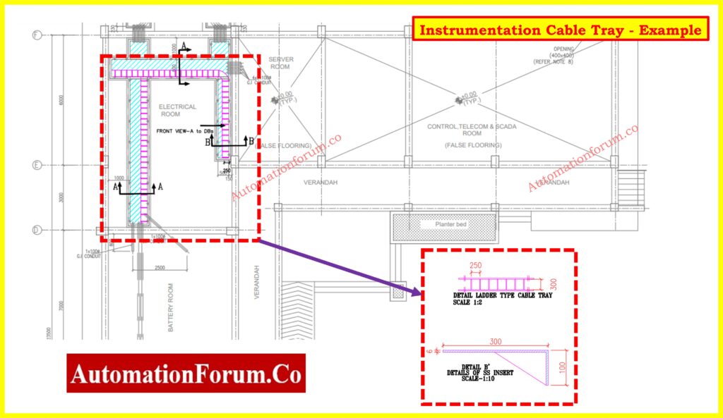
- Cross-check the approved cable tray layout drawings, ensuring they are clearly labeled as “Issued for Construction” (IFC).
- Verify tray routes avoid interference with structural elements, HVAC systems, and other utilities.
Step 3. Material Verification and Coordination
- Verify that the supplied cable trays, supports, clamps, and accessories meet all requirements and are free of corrosion, damage, and missing parts.
- Verify that the materials are appropriate for the environment (for example, stainless steel for corrosive settings, and galvanized steel for normal circumstances).
- To prevent conflicts with other services, like HVAC ducts, piping, and structural supports, coordinate with other disciplines.
- Make sure that cable trays are free from machinery, soffits, and walls.
- Ascertain the inspection team’s familiarity with relevant codes and standards, including IEEE guidelines and IEC 60364.
Step 4. Installation Layout and Preparation
Tray Routing and Compliance
- Check that trays follow the designated pathways outlined in the approved layout drawings.
- To maintain cable integrity and longevity, ensure there are enough clearances from heat sources and vibrating equipment.
Separation of Cables
- To avoid Electromagnetic Interference (EMI), ensure that power cables and instrumentation signal cables are routed in different trays with at least a 300-mm clearance.
- Use barriers or specialized trays to segregate intrinsic safety (IS) cables from non-IS cables, in accordance with project and safety regulations.
- Intrinsic and non-intrinsic safety cables: Minimum of 150 mm, with barriers built as indicated.
Supports and Spacing
- Inspect tray supports for adequate alignment, spacing (usually 1.5-2 meters for horizontal runs), and secure anchoring to prevent sagging or misalignment.
- Confirm that vertical trays have appropriate intermediate supports to provide stability and load management.
Distance and Clearances
- To avoid obstacles or mechanical interference, measure the horizontal and vertical clearances between trays and neighboring structural elements.
- To prevent EMI, ensure that suitable distances are maintained between the power and signal trays.
Expansion and Fire Stops
- Confirm the installation of expansion joints at specified intervals to accommodate thermal expansion and contraction.
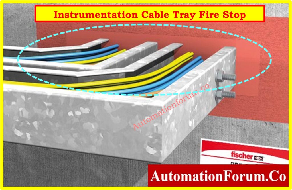
- Check for the presence of fire barriers or sealants at tray penetrations through walls and floors to ensure fire integrity and compliance with safety guidelines.
Step 5. Installation Quality and Safety Inspection
- Inspect tray covers for proper installation to protect against dust, water ingress, and mechanical impact.
- Confirm covers in hazardous or outdoor areas meet relevant IP ratings.
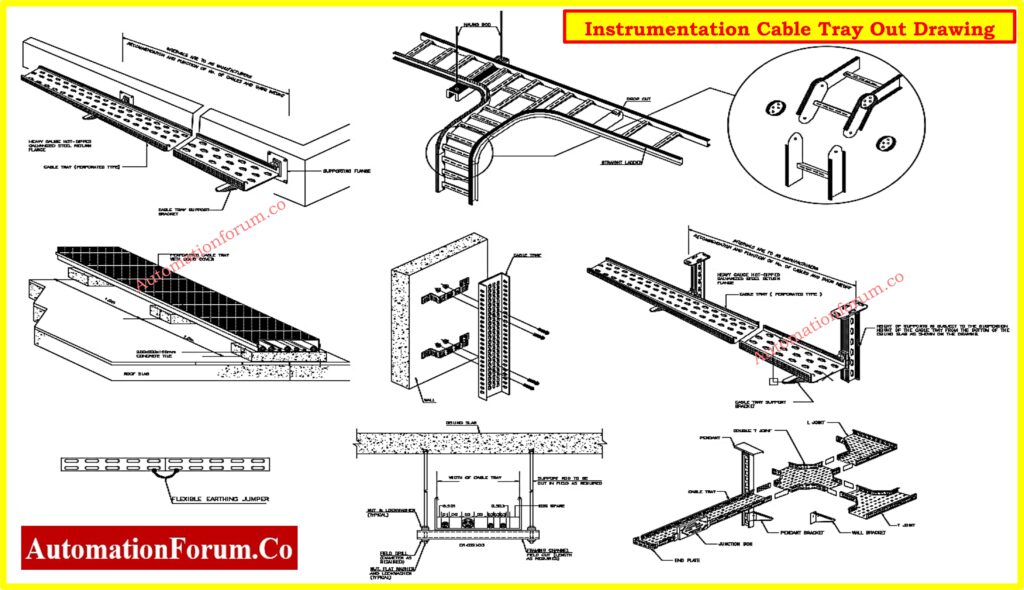
- Check for smooth transitions at tray bends using factory-fitted components to prevent cable stress.
- Verify that sharp edges are deburred and treated with zinc-rich paint.
- Ensure fire-rated sealants are applied to tray penetrations in firewalls and floors.
- Verify cable trays in hazardous areas use certified components and sealing systems.
- Verify segregation of power, control, and signal cables into separate trays to reduce EMI.
- Check for the use of dividers or separate trays for intrinsic safety (IS) cables and standard instrumentation cables.
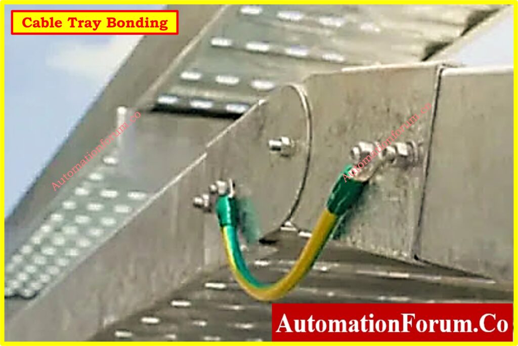
- Inspect bonding jumpers between tray sections and confirm connection to the grounding system.
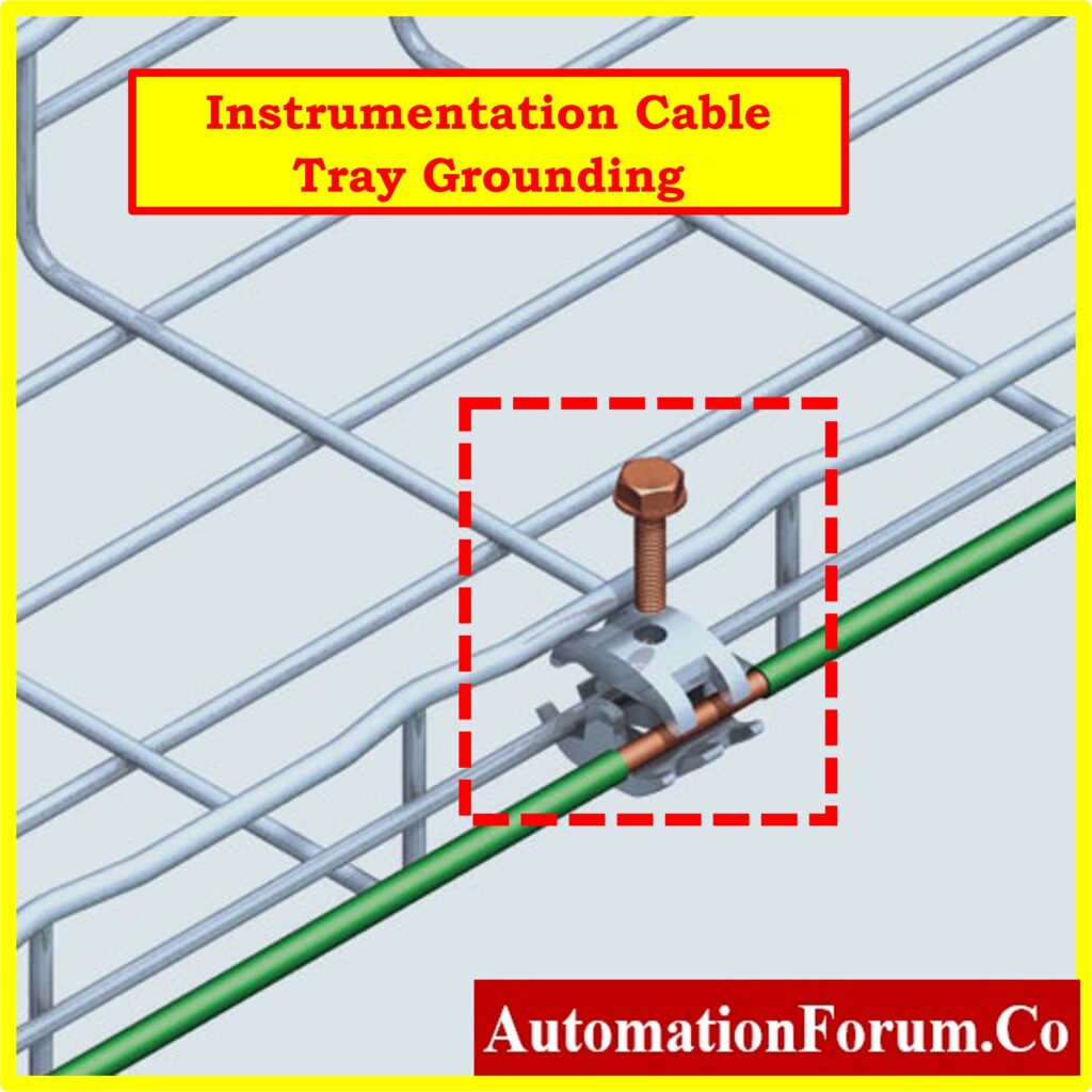
- Conduct continuity tests for tray earthing to ensure compliance with grounding requirements.
- Inspect sealing components at tray ends to prevent dust and debris accumulation.
- Confirm trays in corrosive environments are coated with protective materials or are made of corrosion-resistant alloys.
Refer the below link for the Instrument Earthing Systems
Step 6. Inspection and Testing
- Check that the trays are correctly aligned and leveled according to the arrangement drawings.
- Ensure that all fasteners, couplers, and supports are securely tightened and free of corrosion.
- Check for vertical and horizontal alignment at all places.
- Measure the distance between neighboring trays, parallel runs, and structural parts to ensure they meet project standards.
- Measure the clearances between trays and other services to ensure that they meet standards.
- Ensure that sufficient spacing is maintained between parallel runs to accommodate cable layers.
- Ensure that tray labeling meets the project documents and is visible to maintenance personnel.
- Ensure that identification systems are appropriately implemented.
- Conduct grounding and bonding resistance tests to ensure compliance with standards such as IEC 60364.
- Check the trays for burrs, dents, and sharp edges to avoid cable damage while pulling.
- Inspect the corrosion protection to ensure that it is properly applied.
- Check that all bolts, nuts, and couplers are properly tightened.
- Check for mid-span joints and ensure that all connections are mechanically stable.
- To prevent dust and debris from entering the trays, ensure that all open ends are covered with end covers.
- Ensure that sealing materials are applied correctly at hazardous area transitions.
Click here to know more about Earthing Drawing
Step 7. Documentation and Final Inspection
- All inspection findings should be recorded in the project’s quality inspection log.
- Document any variations from the design or specifications, as well as the corrective steps taken.
- Document corrective measures done and get sign-offs on fixed concerns.
- Ensure that any variations during installation are represented in updated as-built drawings.
- Attach all test findings, including ground continuity, alignment verification, and physical inspection information.
- Prepare a thorough package that includes material inspection reports, tray routing information, grounding test results, and authorized as-built drawings.
- Obtain permissions from the quality assurance team, EPC management, and customer representatives prior to project closure.
- Obtain approval from the project’s quality assurance team, customer representatives, and other stakeholders.
Key Points to Ensure Compliance with Standards
- Follow all safety measures and ensure compliance with applicable standards (for hazardous situations, see IEC 60079).
- Ensure that all installations adhere to the approved layout drawings and technical standards without variation.
- Maintain exact separation of power and signal runs to reduce Electromagnetic Interference (EMI). Shielding is recommended for high-accuracy instrumentation signal lines, particularly in sensitive applications.
- Using specialized trays or barriers, ensure that Intrinsic Safety (IS) cables and non-IS cables are properly separated. Ensure that all IS components are properly labeled and that barriers are erected in accordance with design specifications.
- To improve safety and signal integrity, ensure that all trays and related wires are grounded and bonded.
- Inspect installations in hazardous locations to ensure strict compliance with IEC 60079 and any applicable explosive atmosphere requirements. Check for the usage of approved components and good sealing at hazardous area transitions.
- Continuously monitor the inspection process to identify and rectify concerns as they arise, ensuring quality and project compliance.
Instrumentation Cable Tray Installation inspection Checklist – Download link
Proper cable tray installation is critical for ensuring the safety, reliability, and performance of industrial instrumentation systems. This checklist is designed to guide installation teams, supervisors, and quality inspectors in verifying compliance with project standards, electrical codes, and industry best practices.
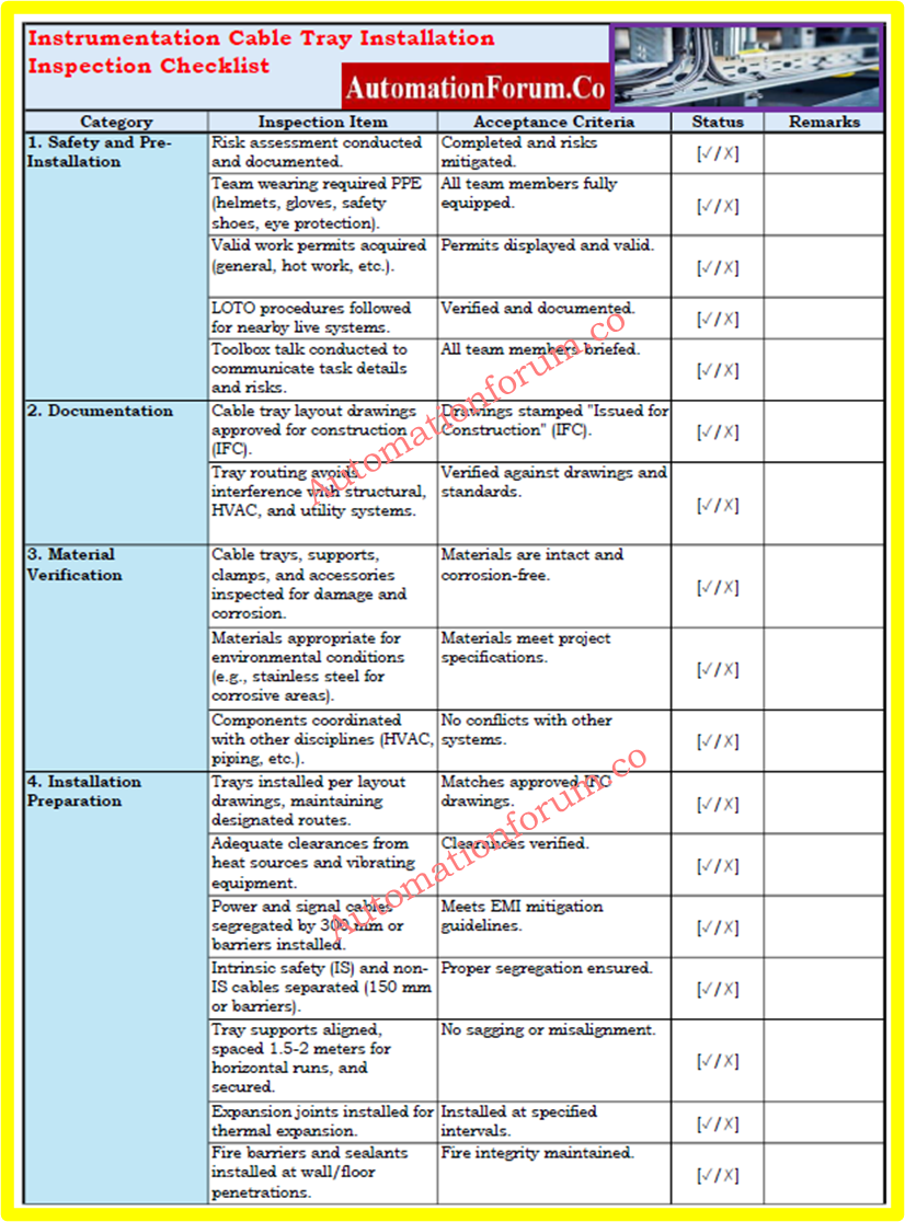
The checklist covers all stages of the installation process, including pre-installation preparation, material verification, tray layout, installation quality, safety inspections, and documentation. It also ensures adherence to international standards such as IEC 60364, IEEE, and guidelines for hazardous areas like IEC 60079.
This checklist is provided in an easy-to-use Excel format, allowing users to:
- Record inspection results: Mark items as “Yes,” “No,” or “Not Applicable” directly in the sheet.
- Add comments: Include remarks or corrective actions for non-compliance items.
- Track progress: Monitor the completion status of each section of the checklist.
- Maintain documentation: Use the filled checklist as part of project quality records.
Refer the below link to download the instrumentation Cable Tray Installation Checklist (Excel format)
Click here for 50+Collection of Essential Instrumentation and Automation Control System Checklists
FAQ on Instrumentation Cable Tray Installation
What is the IEC standard for cable trays?
The IEC 61537 standard outlines the requirements and tests for cable management systems, including cable trays. It ensures quality, safety, and reliability in electrical installations, making it a critical standard for compliance in cable management solutions.
What is the NEC standard for cable tray installation?
Cable trays can be installed in any type of building or structure as long as they comply with the installation and support requirements defined in NEC Article 392. Per NEC Article 392.10(B)(1), the smallest single conductor size allowed for installation in a cable tray is 1/0 AWG.
What is the preferred spacing for cable trays?
For cable trays used in instrumentation and control applications, a rung spacing of 6 to 9 inches (150 to 230 mm) is recommended. This spacing is ideal for supporting small multi-conductor cables and ensuring proper cable management.
What is the minimum thickness of a cable tray?
The minimum thickness of a cable tray depends on its duty classification:
- Light Duty Cable Tray: Thickness ranges from 0.8 to 2.0 mm, with a height of 15–20 mm.
- Medium Duty Cable Tray: Thickness ranges from 1.0 to 2.0 mm, with a height of 25 mm.
- Heavy Duty Cable Tray: Thickness is ?1.0 to 2.0 mm, with a height of 35 mm or more.
These values ensure structural integrity and suitability for specific load requirements.
Click here for Instrumentation Cable and Wiring Inspection Procedure: Essential checklist for Project Engineers