Calibrating LVDTs (Linear Variable Differential Transformers) is an important part of keeping these sensors accurate and reliable in industrial applications.
Purpose and Scope
Calibration of LVDTs typically occurs to make sure that these sensors work within the allowed ranges for accuracy and precision. This complete guidance steps to provide an accurate, step-by-step approach for calibrating LVDTs, covering everything from instruments needed to safety tips, calibration setup, and data recording.
Tools Required for LVDT Calibration

- LVDT (Linear Variable Differential Transformer): The primary sensor that measures linear displacement.
- Reference Standard: Micrometer or Gauge Block: Provides a known and precise displacement for calibration purposes.
- AC Power Source: Supplies the required power to the LVDT. The voltage and frequency should align with the specifications provided in the LVDT’s datasheet.
- Multimeter: Used to verify the input voltage from the power source and also measure the output voltage of the LVDT.
- Data Recorder (Optional): A device for recording and storing calibration data. While optional, a data recorder can streamline the calibration process and provide a detailed record for future reference.
- Test leads and probes
- Soft Cloth for cleaning
- Necessary hand tools
Safety Tips while Handling LVDT
- Please see the link below for further information on fundamental safety and general rules, as well as specifics on calibrating activities in process industries.
Calibration Process in Process Industries: Basic Safety and General Considerations
- Ask the panel operator to configure the controller in manual mode for the LVDT control loop and MOS mode for the ESD control loop.
- Locate the LVDT that you want to disconnect. Check that it is the correct LVDT and make a note of any relevant details. (for example, Tag number, the manufacturer, model number, pressure range, and so on).
- Turn off the power to the LVDT. Check that the power has been turned off at the source from any nearby junction box or marshalling panel near the control room.(For example, disconnect the wires or switch off the breaker).
- Depending on the type of system, you may need to isolate the system before disconnecting the LVDT. Follow the correct steps to isolate the system (for example, the LOTO process).
- Carefully disconnect the electrical connections from the LVDT. Follow any appropriate safety precautions (such as wearing insulated gloves or PPE) and take care not to damage the cables or connectors. Secure the wiring connection information as well.
- The core extension connections of the LVDT should be disconnected from the moving part of the device. Depending on the type of connection, this could contain lock nuts or release clamps. Take cautious not to damage any LVDT core extensions. Mark the LVDT and core position using control equipment as well.
- After separating the LVDT, mark it with any important information (such as the date, the reason for removal, etc.) and store it safely. If the LVDT needs to be installed again, make sure to store it safely to avoid contamination or damage.
Calibration Setup

- The calibration equipment has to be placed in a place that is free of vibrations and electromagnetic interference. Also, the LVDT calibration space has to be well-ventilated and bright.
- Collect all of the essential tools and equipments for the LVDT calibration.
- Ascertain that the LVDT is correctly connected to the given AC power source.
- Check that the voltage and frequency of the AC power source match the specifications of the LVDT.
- Connect the multimeter to the LVDT’s output terminals.
- To correctly measure the alternating current output, switch the multimeter to AC voltage mode.
- Prepare a Reference Standard Adjust the reference standard (micrometer ) to zero.
- Calibrating tools with NIST traceability ensures accuracy by aligning measurements with National Institute of Standards and Technology standards, guaranteeing reliability in industrial applications
- This is usually the position where the LVDT core is completely inside the sleeve as illustrated in the sample figure
- Place the LVDT in a stable position where it won’t be subjected to unnecessary vibrations or movements.
- Place the LVDT in a stable location where it will not be subjected to unnecessary vibrations or movements.
Recording Null Voltage
- Turn on the LVDT and wait for it to stabilize.
- Prepare the reference standard (micrometer or gauge block) and set it to its zero position.
- The zero position is typically the point where the core of the LVDT is fully inside the sleeve, indicating the initial or null position.
- Using the multimeter connected to the LVDT output terminals, record the null voltage.
- The null voltage is the output voltage of the LVDT when the reference standard is at its zero position.
- This recorded null voltage serves as a crucial reference point for the calibration process.
- Clearly document the recorded null voltage, associating it with the zero position of the reference standard.
- This documentation is essential for comparing subsequent measurements and ensuring the accuracy of the LVDT readings.
How do you calibrate a LVDT sensor?
Calibration procedure

Upward Direction
- Incrementally adjust the reference standard to increase the displacement in the upward direction.
- Ensure smooth and controlled movements to accurately capture the LVDT’s response to changing positions.
- Record the output voltage of the LVDT at predefined intervals or specific known displacement points.
- Systematically document the relationship between the position of the reference standard and the corresponding output voltage.
- Continue the upward displacement, recording the output voltage at each known position.
- Capture data for a comprehensive range of upward displacements to cover the calibration span.
Downward Direction
- Once the upward calibration is complete, reset the reference standard back to the null position.
- Begin gradually decreasing the displacement in the downward direction.
- Record the output voltage of the LVDT at predefined intervals or specific known displacement points as you move downward.
- Systematically document the relationship between the position of the reference standard and the corresponding output voltage during downward displacement.
- Continue the downward displacement, recording the output voltage at each known position.
- Ensure comprehensive coverage of the downward calibration range to mirror the process conducted for upward displacement.
Recording Calibration

- Plot the recorded output voltages against their respective known displacements for both upward and downward directions.
- Create separate calibration curves for upward and downward movements.
- Analyze both calibration curves to compare the LVDT’s response in upward and downward directions.
- Identify any asymmetries, non-linearities, or differences in behavior.
- Ensure that the sensor’s response is consistent and proportional to displacement changes in both directions.
- If non-linearities or discrepancies are observed in either direction, consider making adjustments.
- Adjust sensitivity or other calibration parameters to improve the linearity of the calibration curves
- Recalibration is necessary if the output voltage of LVDT does not fall within an acceptable range. Once again, an LVDT has to be repaired or replaced if the output values have deviated from the allowed range.
Documentation
- Record the mechanical position and actual output voltage at each calibration point.
- Document residual null voltage for zero adjust data.
- Include sensitivity calculations and any adjustments made during calibration.
- Clearly note any adjustments made during the calibration process.
Completion of Calibration
- After the calibration has been successfully completed, apply the calibration label to the LVDT.
- When the calibration is complete, clean the equipment, store it in a secure location, and save the LVDT calibration data for future use.
- Unplug the loop calibrators, pressure gauge, and other equipment.
- Reinstall the LVDT in the processing area.
- Make sure the workplace is clean.
- Remove the equipment’s isolation.
- Restore the bypassed or suppressed signal to its original level.
- Restore the LVDT to service and ensure that it is working properly.
With our extensive experience, we ensure precise LVDT calibration, adhering to safety protocols. Our systematic approach ensures accurate measurements and reliable LVDT sensor performance in industrial applications.
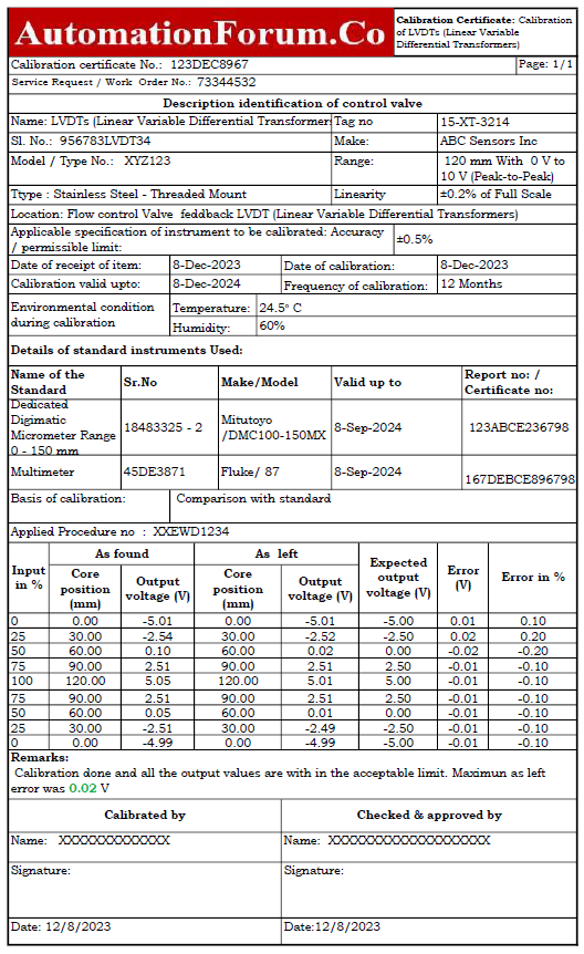
Sample Calibration Report
The next picture shows that the LVDT sample report of calibration was done in workshop with a micrometer as the reference.
You may get the Excel document that was used to construct the LVDTs (Linear Variable Differential Transformers) calibration report by clicking the link below.
Click here to know more about LVDT.
Click here to know more about LVDT Calculator, to calculate Maximum Output Voltage of LVDT (VMax), Output Voltage at Core Displacement of LVDT (Vout), LVDT Core Position at output voltage (D) and Voltage Change from +mm to -mm Core Displacement (Vchange).
Click here to know more about LVDT Maintenance procedure with downloadable check list.