- What is LVDT – Linear Variable Differential Transformer ?
- What is a LVDT used for?
- What is linear displacement measurement ?
- What does LVDT measure?
- How LVDT’s are constructed ?
- How does an LVDT work? What is the LVDT principle
- LVDT Operation for Precise Displacement Measurement
- LVDT Applications in Various Industries
- Advantages and Disadvantages of LVDTs
- Types of Linear Variable Differential Transformer (LVDT)
- Summary
What is LVDT – Linear Variable Differential Transformer ?
The Linear Variable Differential Transformer, or LVDT, is a fundamental electromechanical transducer that is frequently used to convert rectilinear motion into an electrical signal.
The electromagnetic induction law of Faraday, which states that “the magnetic flux across a circuit is directly proportional to the net induced emf in the circuit,” and that “a bar magnet moved through a coil wound with wires can change the magnetic flux of the coil” is the foundation for the operation of Linear Variable Differential Transformer (LVDTs).
What is a LVDT used for?
It is highly accurate and can measure ranging from tiny fractions of an inch to bigger displacements up to ±30 inches (±0.762 meters). The LVDT is made up of a primary winding and two secondary windings that are strategically positioned to give a differentially varied output signal based on the axial position of its movable core. This transducer is critical in a variety of applications because it provides a consistent and accurate technique of converting mechanical movements into electrical signals.
What is linear displacement measurement ?
Linear displacement measurement is the quantification of movement that occurs along a single axis in a single direction. The term “linear” refers to movement along a straight path rather than rotational or angular movement in this context. A linear displacement measurement device can be used to calculate the distance traveled by an object in relation to a reference point. This measurement not only reflects the magnitude of the movement, but also the direction in which the object is moving along the designated axis. Linear displacement measurements are widely used in engineering, robotics, manufacturing, and other disciplines where understanding and tracking linear movement is critical for precision and control.
What does LVDT measure?
An LVDT is an electromechanical sensor that measures displacement by converting mechanical motion into a variable electrical output (current or voltage). Alternately, they can serve as mechanical motion sensors in measuring technologies or as actuators for automatic control systems.
How LVDT’s are constructed ?
construction of an LVDT
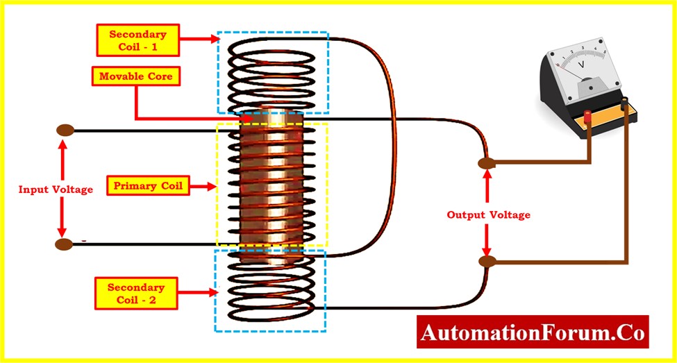
The Linear Variable Differential Transformer (LVDT) consists of a primary winding, two secondary windings, and a movable core. Here’s a detailed description of the construction:
Primary Winding:
- The primary winding is typically located at the center of the LVDT. It is a coil of insulated wire that is energized with an alternating current (AC) power supply.
- This AC excitation induces an electromagnetic field in the core and surrounding windings.
Secondary Windings:
- There are two identical secondary windings, one on either side of the primary winding. These secondary windings are symmetrically positioned and connected in a series-opposing arrangement.
- The purpose of this configuration is to produce a differential output based on the displacement of the core.
Movable Core:
- The core is a magnetic material, often made of a ferromagnetic material, that is free to move along the axis of the coil assembly.
- The core’s movement is typically linear. As the core position changes, it affects the magnetic coupling with the primary and secondary windings.
Outer Housing:
- The entire assembly is housed in a protective casing or tube.
- This outer housing provides mechanical support, protection against environmental factors, and helps maintain the alignment of the coil assembly and core.
Connection Leads:
- Leads or wires extend from the primary and secondary windings, allowing for external connections to an external AC power source for the primary winding and measurement equipment for the secondary windings.
How does an LVDT work? What is the LVDT principle
LVDT Operation for Precise Displacement Measurement
Learn about the operation of the Linear Variable Differential Transformer (LVDT), an essential part of accurate displacement measurement. This electromagnetic transducer converts linear motion into an electrical signal using induction principles. Explore the following characteristics more deeply detail:
Core Movement and Coil Configuration
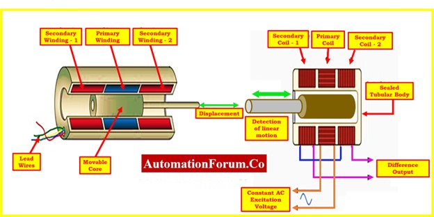
Understand how the three solenoidal coils of the LVDT, which consist of a center primary and two outside secondaries, function to facilitate accurate measurements. A ferromagnetic core moves along the tube’s axis in time with the object’s motion. The alternating current energizes the primary, generating voltages in the secondary to be proportional to the length of the core. Alternating current energizes the primary, inducing voltages in the secondaries proportional to the core’s length, typically at a frequency between 1 to 10 kHz.
Output Voltage Generation in LVDT
Understanding how an LVDT (Linear Variable Differential Transformer) generates output voltage involves exploring different scenarios based on the position of the ferromagnetic core:
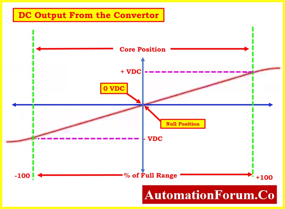
Case:1 Null Position (No Displacement)
At the null position, where there is no displacement from the reference point, the magnetic flux linking with both secondary windings (S1 and S2) is equal. This equality leads to an equal induced electromotive force (emf) in both secondary windings (e1 = e2), resulting in a zero output voltage (e out). The LVDT output indicates no displacement.
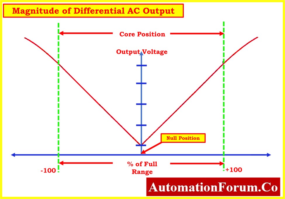
Case:2 Upward Displacement
When the core moves upward from the null position, the flux linking with secondary winding S1 becomes greater than that with S2. This imbalance results in a higher induced emf in S1 compared to S2 (e1 > e2), causing the output voltage (e out) to be positive. This positive output indicates displacement in the upward direction from the reference point.
Case:3 Downward Displacement
Conversely, when the core moves downward from the null position, the magnitude of induced emf in S2 surpasses that in S1 (e2 > e1). This disparity leads to a negative output voltage (eout), indicating displacement in the downward direction from the reference point.
At the central core position, the output is theoretically zero, with minor variations causing a small residual voltage known as quadrature error.
Quadrature Error Mitigation
To address quadrature error in closed-loop systems, modern LVDT systems use fault detection. This involves demodulating each secondary separately, employing precision rectifiers and subtracting DC signals. This method eliminates quadrature error and ensures smooth output voltage transitions through zero at the null point.
Digital signal Processing
Fault detection and ratiometric processing are integrated into systems with digital processing capability. Digital devices create sinusoidal excitation and use multiplexed ADC to execute secondary demodulation, improving accuracy and independence from excitation signal amplitude.
Characteristics of Output Voltage
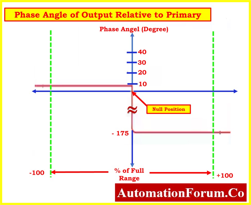
The output voltage of the LVDT is phase-dependent on the core displacement direction (up or down). The amplitude represents the amount of displacement, and a synchronous detector produces a signed output voltage.
Linear Output and Functioning in the Environment
The linear variable displacement transformer (LVDT) is designed with long, thin coils, which ensures linearity over a displacement that’s several inches. Its non-contact architecture improves dependability by permitting the core to move without friction. The LVDT can be totally sealed against environmental conditions due to the lack of sliding or spinning connections.
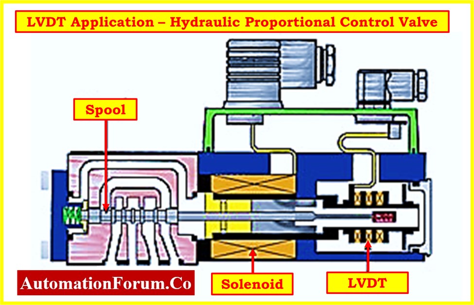
LVDT Applications in Various Industries
- Automated Machinery: Monitor and control the position of moving components for precise manufacturing processes.
- Robotic Systems: Provide real-time feedback on the position of robotic arms, grippers, and other moving parts for accurate task execution in robotics.
- Conveyor Systems: Ensure precise positioning of items in conveyor systems, contributing to smooth and reliable operations.
- Process Control: Contribute to efficiency by providing continuous and accurate data on the location of elements in automated systems, maintaining optimal conditions.
- Quality Assurance: Enhance quality assurance measures by ensuring accurate positioning and movement of components, minimizing defects in production.
- Real-time Monitoring: Enable real-time monitoring of positional changes, allowing prompt adjustments in automated systems to variations for improved reliability.
- Aircraft Control Systems: Integral for precise position and displacement measurements in controlling wing and flap positioning, ensuring optimal aerodynamics application.
- Landing Gear Positioning: Provide real-time feedback on landing gear components, contributing to smooth and controlled landings during takeoff and landing.
- Thrust Vector Control: Utilized in advanced aircraft and rocket systems for precise adjustment of thrust direction, enhancing aircraft flight path.
- Aircraft Engine Systems:Monitor and control the position of components like variable inlet guide vanes and nozzles, contributing to optimal engine performance and fuel efficiency.
- Flight Control Surfaces: Used for positioning and control of ailerons, elevators, and rudders, ensuring accurate response to pilot commands for aircraft stability.
- Hydraulic Systems: Offer accurate position feedback for cylinders and actuators in hydraulic systems, ensuring precise control of oil powered mechanisms.
- Automotive Systems: Employed in critical areas like suspension systems and throttle position sensing in vehicles, optimizing performance and efficiency.
- Mechatronic Systems: Play a pivotal role in mechatronic systems, ensuring precise positioning in medical devices, industrial machinery, and scientific instruments.
- Medical Devices: Essential for accurate positioning in medical devices, such as robotic surgical systems and imaging equipment, ensuring high-precision procedures.
- Industrial Machinery: Employed in various tasks from material handling to manufacturing processes in industrial settings, enhancing efficiency and reliability.
- Scientific Instruments:Utilized in laboratories, research facilities, and experiments for accurate measurements and position control in scientific instruments.
Advantages and Disadvantages of LVDTs
Advantages: Why Use an LVDT?
- High Linearity: High linearity in displacement measurements is provided by LVDTs. This indicates that there is excellent accuracy and an exact relationship between the input (displacement) and the output (voltage).
- High Resolution: High-resolution data from LVDTs enable accurate and thorough tracking of displacements. This is important for applications that need the analysis and capture of small movements.
- Temperature Sensitivity: LVDTs are capable of displaying minimum temperature sensitivity, ensuring consistent operation in a range of environmental circumstances. This quality increases their dependability in various operating circumstances.
- Contactless Operation: The contactless operation of LVDTs is one of its main benefits. Because there is no physical contact between the coil assembly and the core, there is less wear and tear over time, which adds to long-term durability.
- Longevity and Reliability: LVDTs have a reputation for having a robust design, which contributes to their long-term durability and dependability. This durability is especially useful in applications where precise and continuous measurements are necessary.
- Wide Measurement Range: From fractions of a millimeter to many inches, LVDTs are capable of handling a wide range of displacement measurements. They can be used in a variety of applications with different measurement requirements because of their adaptability.
Disadvantages:
- Sensitive to Vibrations: LVDTs have the potential to pick up noise in measurements due to their sensitivity to external vibrations. This sensitivity may be a drawback in situations when it is difficult to maintain a stable environment.
- Electromagnetic Interference: LVDT performance may be disrupted in high electromagnetic interference conditions. It takes careful installation and shielding to mitigate this disadvantage.
- Cost: When compared to some other displacement sensing technologies, the initial cost of LVDTs may be rather elevated. This element could have an impact on the method of making choices, especially in instances where budget is restricted.
- Size and Weight: The physical dimensions of LVDTs may be a restriction in some applications where size and weight are important considerations. Although there have been attempts at miniaturization, it remains something to think about in some situations.
- Complex Signal Conditioning: Because LVDTs normally provide AC voltage as their output signal, processing and interpretation of the signal require extra signal conditioning. In devices with limited processing capability, this level of complexity could be a problem.
Types of Linear Variable Differential Transformer (LVDT)
Linear Variable Differential Transformers (LVDTs) can be classified based on various factors, including their measurement method and the armature mechanism. Here’s an overview:
Based on Measurement Method
AC-AC LVDT:
- Uses an AC input signal and measures the AC output signal.
- Provides high sensitivity and good noise immunity.
- Commonly used in applications where noise rejection is critical.
DC-DC LVDT:
- Utilizes a DC input signal and measures the DC output signal.
- Simplicity and ease of signal processing.
- Suitable for applications where a DC signal is preferred or required.
AC-DC LVDT:
- Employs an AC input signal and measures the DC output signal.
- Combines the sensitivity of AC with the stability of DC.
- Provides a balance between sensitivity and stability.
Based on Armature Mechanism:
Unguided Armature LVDT
- Armature is loosely attached to the specimen, requiring separate support for the LVDT body.
- No wear, infinite resolution, suitable for delicate measurements.
- Used for precision measurements where resolution is critical.
Captive Armature LVDT
- Armature is guided and restrained by a low-friction assembly.
- Suitable for long working ranges, helps prevent misalignment.
- Suitable for robust measurements in vibration environments with potential misalignment challenges.
Force-Extended Armature LVDT
- Uses internal spring, pneumatic force, or electrical motor to continuously push the armature to its fullest extension.
- Suitable for slow-moving applications, no direct connection between armature and specimen required.
- Applied for Slow or dynamic measurements where a continuous force is needed.
Summary
The Linear Variable Differential Transformer (LVDT) is a precise electromechanical transducer converting linear motion into electrical signals. Highly accurate, it measures displacements, ensuring wide applicability. LVDTs offer advantages like high linearity and resolution but may be sensitive to vibrations and have cost considerations.
Click here to know more about LVDT Calculator, to calculate Maximum Output Voltage of LVDT (VMax), Output Voltage at Core Displacement of LVDT (Vout), LVDT Core Position at output voltage (D) and Voltage Change from +mm to -mm Core Displacement (Vchange).
Click here to know more about LVDT Maintenance procedure with downloadable check list.
Click here to know more about LVDT calibration.
 in diverse industrial environments.)