- What is an instrument junction box?
- Why is a junction box necessary?
- Why are junction boxes required?
- What does a junction box contain?
- Instrument Junction Box Schematic Example:
- How do we choose a junction box?
- What is a Junction box schedule?
- What is included in the Junction box schedule?
- What is the purpose of the Junction box schedule?
- Below is an example of a JB schedule:
A Junction box schedule is a document that lists all of the instrument junction boxes. Information like the JB position, tag number, size, make, IP rating, cable specifications, gland details, termination specifications, and earthing details are all mentioned in this document.
What is an instrument junction box?
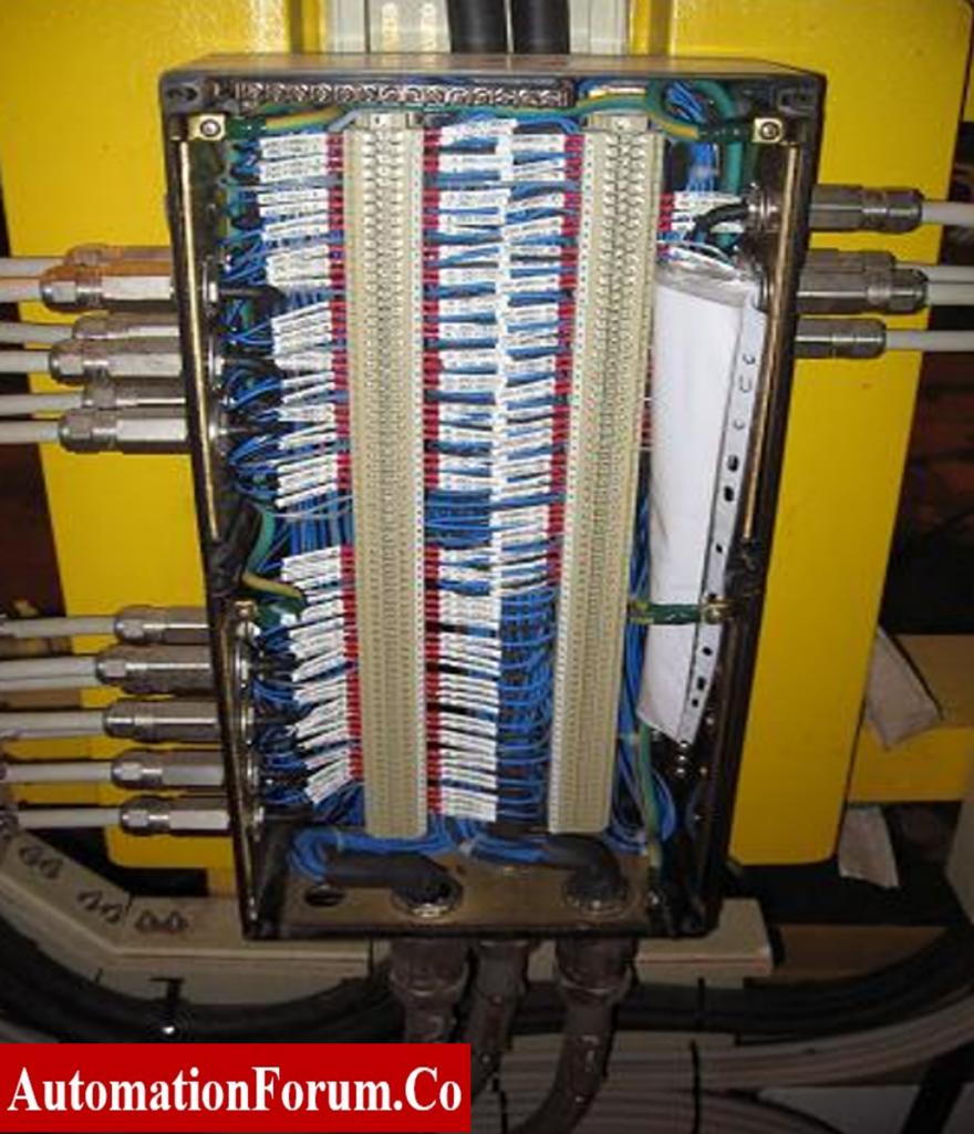
An instrument junction box is a type of enclosure that is used to protect and organize electrical or electronic instruments and their associated wiring.
Instrument junction boxes are typically made of metal or plastic and are designed to be rugged and durable. They will have features such as removable covers, terminal blocks, and cable glands to allow for easy installation and maintenance of the instruments and wiring.
The purpose of an instrument junction box is to provide a centralized location for the instruments and their wiring, which can help to reduce clutter and improve safety in the area where the instruments are being used. It can also help to protect the instruments wiring from damage due to environmental factors such as moisture, dust, and vibration.
Why is a junction box necessary?
A junction box is a type of electrical enclosure used to connect cables between field devices and the control room. It contains cable termination terminal strips. Junction boxes are required in every electrical, control, and instrumentation installation
It is an enclosure used to connect field devices (i.e., instruments) in the process/production zones to control/monitoring equipment, which is typically located in the control room.
Why are junction boxes required?
The junction box is typically intended to terminate many field devices of shared systems in a process area.
When designing instrument junction boxes, the environmental characteristics of the planned locations should be taken into account. It must be certified in order to ensure adequate ingress protection (IP) and hazardous area protection
What does a junction box contain?
The components of a junction box include, but are not limited to:
- Terminal block that includes terminal strips for cable connection
- Cable gland earthing plate
- Isolated earth bar for the connection of the screen of I/O signal cable.
- Gland plugs/ breather
- Terminal block mounting rail with end caps.
Instrument Junction Box Schematic Example:
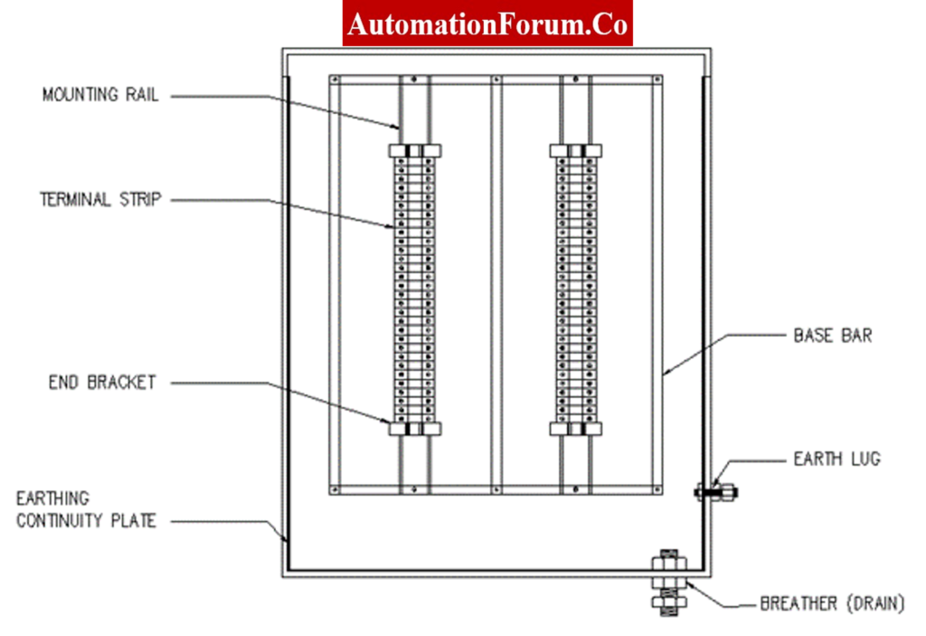
Mounting Rail:
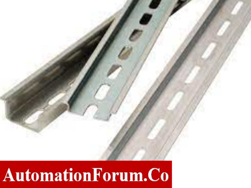
Rails are the metal bars inside an electrical enclosure that are used to mount circuit breakers and other types of electrical equipment. DIN rails are very important for the installation, maintenance, and operation of electrical equipment, but their design is relatively simple. Some of the types of equipment that might be attached to a DIN rail are:
- Breakers used in electrical circuits
- Terminal blocks
- Programmable logic controllers
- Motor controllers
- Relays
To stay in place and work properly, these parts need solid mechanical support. But most of the time, they’re not made to be mounted directly to a wall or a panel in an electrical enclosure. Most of the time, designers and builders of devices use a DIN rail to mount these parts.
Terminal Strip:
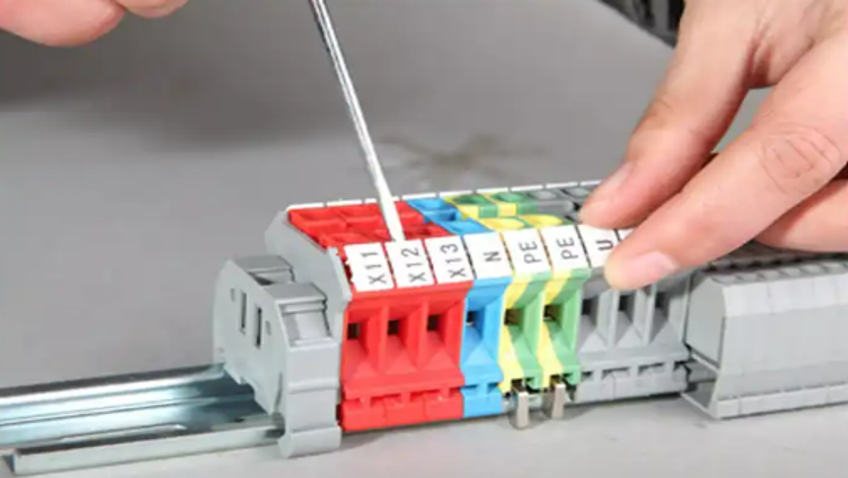
The primary function of the terminal strip is to make it possible to connect the panel’s internal and external peripherals. Therefore, all of the connections between the equipment and the central panel must be done through the strip. Switchboard installation and connection are made simpler by the terminal strip. Practically speaking, it is claimed to arrange the wiring and secure the panel’s mechanical and electrical safety. Additionally, it aids in machine maintenance, making it simpler to find any defects in machinery and cables linked outside of the switchboard. A terminal or junction connector is a piece of equipment that functions in the capacity of a wire connection. Consequently, it serves as a secure connecting point for cables or plugs to connect to equipment.
End bracket:
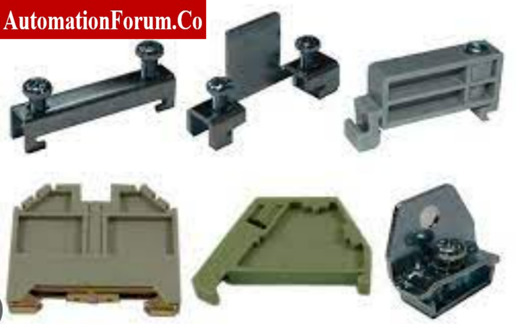
End clamps, also called End Stoppers, are used to hold a stack of terminal blocks on the mounting rail. End clamps come in different sizes and styles, depending on the profile of the terminal block stack and the mounting channel. They are made of Polyamide or Mild Steel that has been properly plated.
Earthing continuity plate:
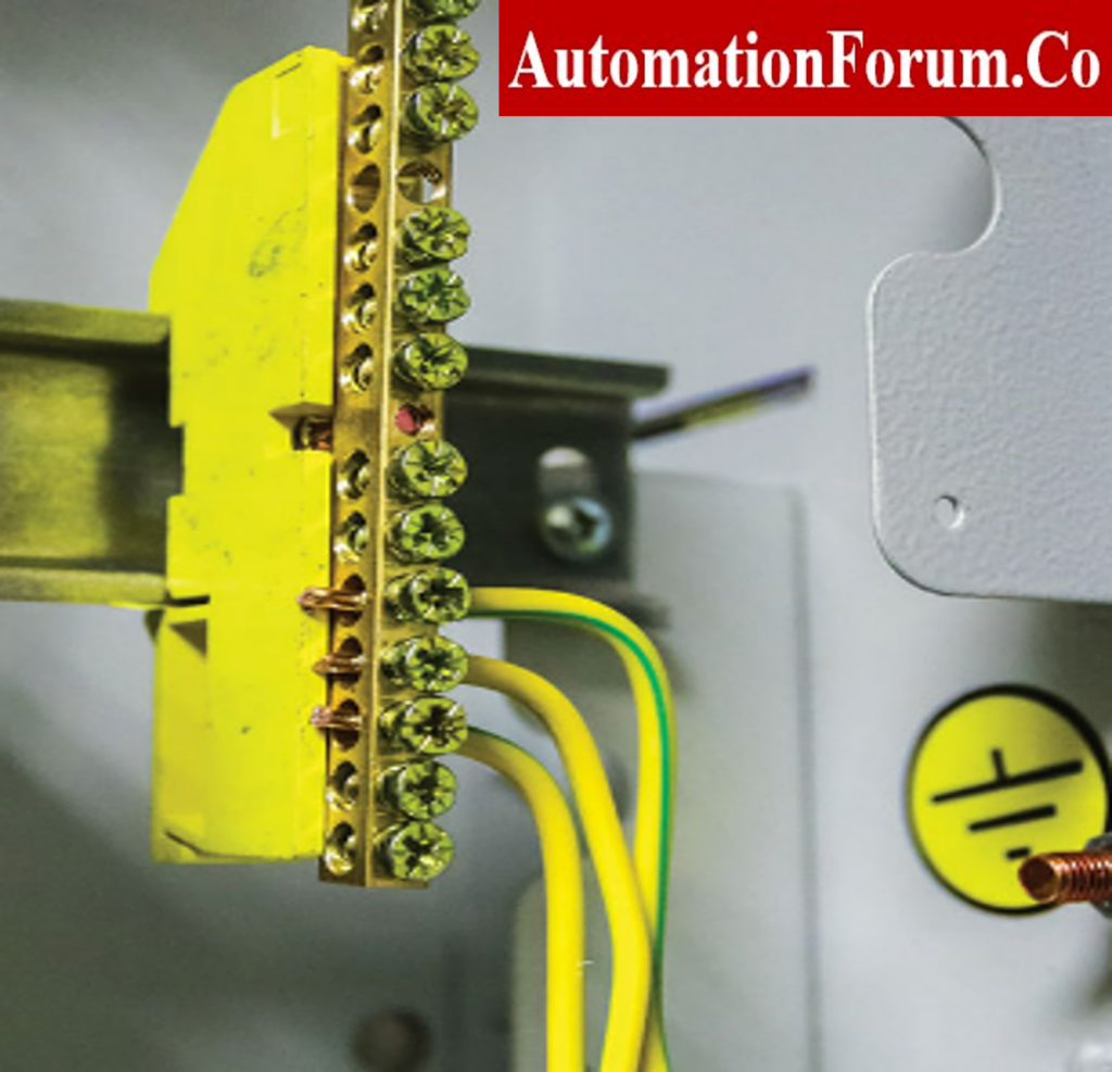
The wire that connects different electrical devices and appliances, such as a junction box, distribution board, plugs, and equipment. In other words, an earth continuity conductor is the wire that connects the earthing lead to the electrical device or equipment.
Base bar:

The terminal blocks of a junction box are typically positioned in the rear base bar with din rail that is included inside the junction box .
The main reason to use a terminal block backplate is to keep a junction box’s IP rating. Backplates are mostly made of normal steel or SS316/SS316L.
Earth Lug:

An earthing lug is a component that attaches to an object and allows for easy grounding. In grounding applications, lay-in grounding lugs are used to bind wires and surfaces together. These lugs are intended for a simple and speedy installation process.
Breather:

Breather drains help equalize the pressure between enclosures and the outside air. This keeps moisture from building up in places where the temperature changes or it is humid. Also, they effectively drain any water that has condensed inside the device. Exd/Exe hazardous area breather drains are made to drain water out of an enclosure, let air from the enclosure escape into the air around it to prevent moisture buildup, and provide the explosion-proof safety needed in a hazardous area.
Junction Boxes for digital instrument signals should include a bus bar for connecting the screens of individual cables to the screens of multipair cables.
In accordance with standard procedure, the junction box must be divided for the following functions:
- Signals for PCS and SIS
- Analog signals and Digital signals
- Signal with various voltage levels
How do we choose a junction box?
Following are the important standards for instrument junction boxes:
- Materials
- Degree of protection
- Type of terminal
- Cable entry direction and devices
- Earthing
- Temperature class and gas group
- Drain plug
- Enclosure size
- Labels
- Terminal block back plate
- Doors
- Ambient temperature
What is a Junction box schedule?
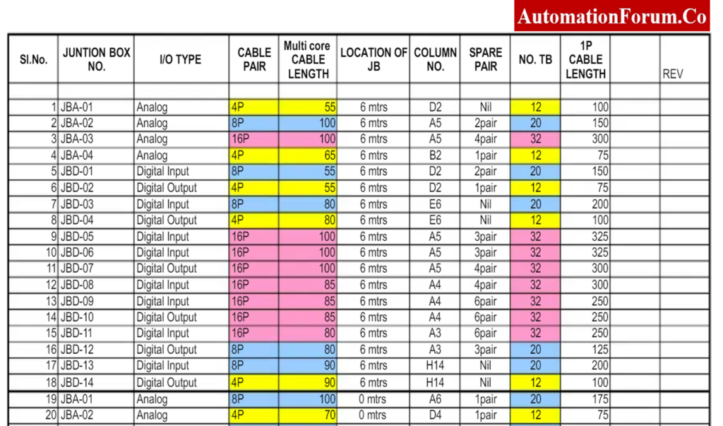
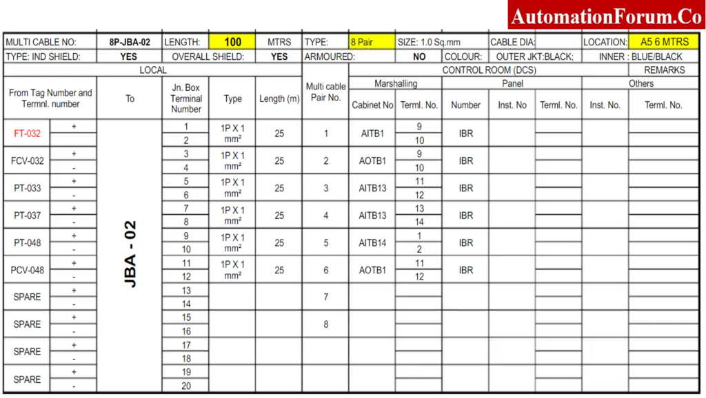
A “Junction Box Schedule” is a document that contains a list of instrument junction boxes. This document specifies the cable and gland required by each instrument connection.
What is included in the Junction box schedule?
The following information is listed on the JB schedule:
- JB Type
- Specification
- JB Number
- Termination information for the source and destination
- Type and size of the gland for every incoming cable
- JB Size
- JB Location
What is the purpose of the Junction box schedule?
The purpose of a junction box schedule is to provide a clear and organized record of all of the instruments and devices that are connected to a particular junction box, as well as their associated wiring.
This can be helpful for maintenance, troubleshooting, and repair purposes. It can also help to ensure that all of the instruments and devices are properly installed and connected, and that the wiring is in good condition.
JB schedules are utilized as a guide when creating material take-offs for the purchase of JBs.
Below is an example of a JB schedule:
 schedule as well as its applications.)