- Purpose: Live Signal Verification for 4-20 mA Loops
- Scope: Systems, Transmitters and Exclusions
- Safety Requirements & Work Authorization
- Tools, Test Equipment & Reference Documents
- Pre-Verification Checks Before Measuring Loop Current
- Live Signal Verification Procedure in Operating Plant
- Data Recording and Documentation Requirements
- Acceptance Criteria and Editable Tolerances
- Troubleshooting Guide for Common Loop Problems
- Final Restoration and Close-Out Activities
- Best Practices and Training Recommendations
- Benefits of Live Signal Verification for 4–20 mA Loops
- FAQ on Live Signal Verification – 4 to 20 mA Loop
This Standard Operating Procedure describes a complete and practical method for live signal verification of 4 to 20 mA analog loops used in industrial process plants. It is written specifically for instrumentation technicians commissioning engineers and maintenance professionals who work with transmitters control systems and field wiring. The procedure’s main goal is to check the health of signals in real-world situations and find faults that static calibration can’t find.
Purpose: Live Signal Verification for 4-20 mA Loops
Live signal verification ensures that a 4 to 20 mA loop performs correctly while the process is running. Unlike bench calibration or isolated loop checks live verification evaluates the entire signal path including the transmitter wiring marshalling panels barriers isolators input cards and control system scaling.
This process helps find problems with grounding and shielding, electrical noise interference, wrong barrier behaviour, and input cards. It also makes sure that the real field current is the same as the DCS or PLC process value that is shown. Live verification is critical during commissioning after maintenance and during troubleshooting of unstable or drifting signals.
The One Signal That Never Fails in Industrial Automation: Why Engineers Still Trust the 4-20 mA Signal in Automation Systems
Scope: Systems, Transmitters and Exclusions
This SOP applies to all conventional analog 4 to 20 mA loops including two wire three wire and four wire transmitters. It covers pressure temperature flow level and analytical transmitters connected to PLC or DCS analog inputs.
Loop Faults? Diagnose Any 4-20 mA Problem in Minutes: 4-20 mA Loop Troubleshooting with Loop Calibrators : A Practical Guide
Safety Requirements & Work Authorization
Electrical Safety & Personal Protective Equipment (PPE)
Before starting any live signal verification activity ensure compliance with site electrical safety rules. Wear flame resistant clothing safety shoes helmet eye protection and electrical rated gloves where required. Only use instruments that are insulated and test leads that have been approved. Stay away from open terminals with your hands to avoid short circuits.
Permit to Work & Operations Coordination
If plant procedures say you need one, get a permit to work. Before you touch any live loop, let the control room and operations staff know. Make it clear what the job will entail, particularly whether a simulation or temporary loop opening is intended. Record the name of the operations representative and approval reference.
Lockout-Tagout (LOTO) & Live Work Boundaries
Live signal verification normally does not require lockout tagout since the loop remains energized. If the loop must be disconnected for series measurement or simulation follow the lockout tagout procedure strictly. Never break a loop controlling an active process without operations approval.
Safety Instrumented System (SIS) Restrictions
Refer the below link for Why 4-20 mA Current Signal is Preferred Over Voltage Signal in Instrumentation?
Tools, Test Equipment & Reference Documents
Measurement & Test Instruments (DMM, Clamp Meter, Loop Calibrator, HART Communicator)
Use calibrated instruments suitable for industrial environments. Commonly used tools include a digital multimeter with DC milliamp measurement capability a hand held loop calibrator that can measure and source current a HART communicator for digital diagnostics and a DC clamp meter capable of measuring low current accurately.
Clamp meters are preferred for non intrusive checks. Loop calibrators are required for simulation and linearity testing. All instruments must have valid calibration certificates.
Hand Tools & Site Accessories
Use insulated screwdrivers torque controlled terminal drivers fused test leads insulated crocodile clips and approved intrinsically safe accessories in hazardous areas. Carry a flashlight for cabinet inspection and clean cloths for removing dust or moisture.
Documentation Required at Site (Datasheets, Loop Drawings, I/O List)
Always carry the instrument datasheet loop wiring diagram hook up drawing I O list and loop index. Review previous calibration and verification records before starting work. These papers assist figure out what values are expected and what problems have happened in the past.
Stop Manual Math – Get Exact Process Value Instantly: 4 to 20 mA Transmitter Output Process Value Calculator
Pre-Verification Checks Before Measuring Loop Current
Tag Number & Loop Identification
Check the transmitter tag number in person at the field equipment. Check that it matches the wiring diagram’s loop number and the DCS or PLC tag name. Make sure you’re working on the right loop by checking the terminal numbers on the marshalling panel and the channel assignments on the input card.
Datasheet and Range (LRV/URV) Confirmation
Check the instrument datasheet to make sure the lower range value and upper range value are set correctly. Check that the output signal is 4 to 20 mA and not something else. Make sure that the engineering units and scaling in the control system are the same as those in the transmitter setup.
Visual Inspection of Installation
Inspect the transmitter junction box cable glands and conduit for mechanical damage corrosion loose fittings or moisture ingress. Check that terminal screws are tight and that the cable shield is terminated according to site grounding philosophy. Inspect barriers or isolators for fault indicators or abnormal status lights.
If any physical defect is found correct it before proceeding with live verification.
Convert Hz to mA Without Any Formula or Guesswork: Frequency(Hz) to 4 to 20 mA Signal Conversion Calculator
Live Signal Verification Procedure in Operating Plant
Preparation and Initial Observation
Notify Control Room and Operations Team
- Confirm permit-to-work (if required) and note permit ID.
- Tell the control room the exact start time, estimated duration, and whether you may briefly open the loop or simulate the signal.
- Record the name and contact of the operations representative who acknowledged the work.
PPE, Safe Access and Test Equipment Readiness
- Put on site-specified PPE (FR clothing, safety shoes, helmet, eye protection, electrical gloves if required).
- Make sure that equipment and test leads are insulated and, if necessary, safe to use.
- Verify safe access to the transmitter and marshalling panels (clear walkways, no wet surfaces).
Confirm device identity and paperwork at the device
- Physically read the transmitter tag and serial number at the device and confirm it matches the loop drawing, I/O list and DCS tag.
- Open the loop folder or pull up datasheet, LRV/URV, wiring diagram, marshalling layout and previous verification/calibration record. Note last calibration date.
Baseline DCS/PLC Trend Observation

- Pull up the live trend for the tag and observe for at least 3–5 minutes (longer if signal is known to be intermittent).
- Take a screenshot or print the trend and note the start and end times of the observation.
- Record the PV, engineering units, any alarms that are going off, and the input quality/status bits that the DCS/PLC shows.
Record Ambient Conditions and Process Context
- If there are any corrosive or unclean circumstances, be sure to note the temperature, humidity, and other factors.
- Record process state (steady, ramping, batch cycle, startup/shutdown) and any nearby activities (motor/ compressor starts, valve cycles) that might influence noise.
Prepare Measurement Log and Verification Records
- Create or open the verification log with fields: tag, location, LRV/URV, expected PV, start time, technician, operations contact.
- Verify test equipment calibration sticker/date, set clamp/meter to correct DC mA range, and check meter leads and fuses.
Calibrating a Transmitter? This Tool Saves Huge Time: Transmitter Calibration Span, LRV and URV Value Calculator from Measured 4 to 20 mA
Measurement of Loop Current at the Transmitter
Safe Access to Transmitter Terminals
- Isolate only the terminal cover; do not remove or disturb other wiring unnecessarily.
- Verify which conductors are the signal positive, signal negative, and where the cable shield is terminated. Photograph the terminal layout if helpful.
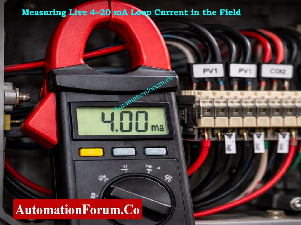
Preferred Non-Intrusive Measurement Using DC Clamp Meter
- Set the clamp meter to DC mA mode (or µA if required). Confirm the clamp can measure DC current for the loop range.
- Separate or spread the conductors so the clamp surrounds only the single positive signal conductor clamping both conductors will read near zero.
- Place the clamp on the positive conductor only, wait for the reading to stabilise, then record: measured mA, time, meter model/ID, and meter calibration date.
- Note any visible cable damage, loose terminals, or corrosion while the cover is off.
Alternative Inline (Series) Measurement with Operations Approval
- Obtain clear, written or radio approval from operations to briefly open the loop. Confirm consequences to process control.
- Switch meter to mA series measurement, verify correct jack/fuse installed, and brief operations that the loop will be open for a few seconds.
- Loosen the positive terminal, insert the meter in series (positive wire → meter → terminal), take the reading quickly, then fully restore the connection and torque to spec.
- Immediately confirm DCS behavior and that no alarms were triggered by the brief interruption. Log duration of open loop and who approved it.
Measurement Recording and Time Synchronization
- Always timestamp each measurement and record the exact meter/clamp settings.
- If multiple readings are taken, average or list each sample with its timestamp.
- Note any discrepancy between successive readings, intermittent jumps, or unstable readings.
Safety Notes and Common Measurement Pitfalls
- Never short loop wires with test leads; avoid inserting scope ground clips across loop conductors.
- If the conductors are in a tight shielded cable and cannot be individually clamped, do not force separation – use the series method only if approved.
- If you see near-zero current unexpectedly, stop and re-check wiring and DCS status before proceeding.
Signal Noise Issues? This Cable Choice Fixes Most Problems: Twisted Pair Cable in Industrial Signal Transmission: The Essential Guide for 4-20 mA and RS 485 Systems
Control System (DCS/PLC) Indication Verification
Simultaneous Field Current and DCS/PLC PV Observation
- While measuring field current, have an operations person or colleague read and record the DCS/PLC PV and input quality flag at the same instant (synchronise timestamps).
- If you cannot observe both simultaneously, take time-stamped meter readings and immediately capture the DCS PV screenshot with the same timestamp.
Conversion of Measured mA to Engineering Units
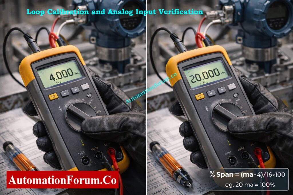
- Convert measured mA to %span: %Span = (mA − 4) / 16 × 100.
- Convert %span to PV: PV = LRV + (%Span/100) × (URV − LRV). Record calculated PV and compare to DCS PV.
- Compute Δ (difference) and Δ as % of span; record whether it is within site tolerance.
Input Quality Status and Alarm Verification
- Record any input quality bits (good, bad, stale, overflow, underflow) and any alarm or diagnostic messages.
- If DCS shows bad/stale but field mA is valid, suspect wiring, marshalling, or input card fault – note immediately for troubleshooting.
Dynamic Response and Signal Latency Assessment
- If process PV is changing, keep track of how long it takes for the DCS to update after the measured mA changes. For reference, write down the scan time or estimated delay.
- If there is any lag, sluggishness, or step changes in DCS PV that don’t match changes in measured current, write them down.
Deviation Analysis and Immediate Corrective Actions
- If you see big offsets, an inverted scale, or input that doesn’t respond, write down exactly what you measured and tell the operations/supervisor.
- If necessary, tag the loop as non-compliant and follow site procedures to take corrective action.
Refer the below link for Understanding the Difference Between Live Zero and Dead Zero in 4 to 20 mA Signals
HART Diagnostics and Device Health Check
Preparation for HART Communication
- Make sure that the transmitter supports HART and that you have a communicator or interface that is safe to use.
- Find the HART connection point (terminal block, local connector) and make sure that safe connection procedures are followed in dangerous regions.
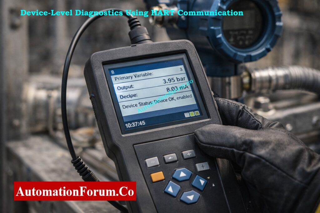
Reading and Recording HART Parameters and Diagnostics
- Query and log the following: primary variable, output current, device status text, device revision, sensor temperature, diagnostics counters, and last calibration date.
- Get HART event logs, warnings, and any maintenance or problem codes that the device shows.
Interpretation of HART Data Versus Measured Loop Current
- Check the output current that HART reports against what your clamp/meter says; write down any differences.
- If HART says there is a sensor error, offset, or saturation, write down the specific code or text and follow the manufacturer’s instructions for fixing it.
Saving Diagnostic Logs and Evidence
- Take screenshots of the communicator or export a device description log (DD) and add it to the verification record.
Escalation of HART Device Faults
- If there are serious device faults or warnings that keep happening, tell the instrumentation engineer and set up a time for follow-up (repair, calibration, or replacement).
- If device events show that maintenance is needed, raise a work order.
Struggling With mA Calculations? This Method Makes It Easy: How to Calculate Temperature Transmitter 4-20mA Output Using Linear Equation and Percentage Method ?
Simulation and Linearity Verification (When Approved)
Preconditions and Operations Approval for Simulation
- Get written or recorded permission from operations to either isolate or imitate the output of the transmitter. Check the rollback plan and safe states.
- Confirm that simulating will not cause unsafe plant actions; if necessary, hold control in manual or coordinate with operations to put the loop into a safe mode.
Loop Calibrator Connection and Configuration
- Isolate transmitter output per site procedure and connect the loop calibrator in source mode using short, secure leads.
- Verify calibrator zero and range; check calibrator’s calibration sticker/date.
Application of Test Points (4 mA, 12 mA, 20 mA)
- Minimum recommended: 4.000 mA (LRV) and 20.000 mA (URV). Add 12.000 mA (midpoint) for linearity check; optional: 8 mA and 16 mA for added confidence.
- Record the test sequence and allow settling time (few seconds) at each step for DCS scan to stabilise.
Linearity, Hysteresis and Error Evaluation
- For each applied current: record calibrator set value, calibrator readback, measured DCS PV and input quality, time, and any transient behaviour.
- Note nonlinearity, hysteresis (if doing up/down sweep), and any lag in DCS reading.
- Calculate PV from each applied mA and compare to DCS PV; document errors and whether they fall within acceptance criteria.
- If errors exceed tolerance, stop and follow troubleshooting (check wiring, isolator, input card, transmitter configuration).
Restoration of Transmitter Output and Functional Confirmation
- Remove calibrator, reconnect transmitter exactly as found, torque terminals to spec, and confirm loop returns to measured live mA and DCS PV.
- Make final log entries showing pre-test and post-test live values.
Test Any Control Loop Without the Real Process: How to simulate 4-20ma signal with Loop Calibrator ?
Stability Monitoring and Noise Evaluation
Selection of Monitoring Method and Duration
- Use a clamp meter with logging, handheld data logger, or take manual samples every 30 s–1 min for 10–15 minutes as a minimum. Longer monitoring may be required for intermittent problems.
Continuous Recording and Min/Max Capture
- Record minimum, maximum and average mA during the monitoring period and the time stamps of extrema. Save DCS trend capture aligning with the same period.
Noise Band and Stability Metric Calculation
- Compute peak-to-peak noise = Imax − Imin. If you want to measure how variable the samples are, you can calculate the standard deviation.
- Check noise measurements against the approval criteria, which in this case is 0.05 mA p-p.
Identification of Transients and Correlation with Plant Events
- Take note of any spikes (brief bursts of high amplitude), dropouts (sudden or near-zero loss), or oscillating patterns, and write down the exact times.
- To find connections, compare timestamps to known plant events such motor starts, valve actuations, and instrument air events.
Grounding and Shield Sensitivity Check
- With operations aware and while the loop remains connected, inspect shield termination and, if safe, lightly touch the shield termination to test sensitivity. Record any change in mA or DCS PV.
- If touching the shield alters the signal, document the behaviour and recommend a grounding fix (one-end shield termination, isolation, or rerouting).
- If intermittent spikes or dropouts are infrequent, plan extended logging (hours/days) or request DCS historian extraction for deeper analysis.
- Raise corrective work orders for wiring replacement, isolator replacement, or further electrical investigation if instability persists.
There’s a Safety Reason Engineers Avoid 0-20 mA: Why not use 0-20mA & 0-15psi instead of 4-20mA & 3-15psi?
Data Recording and Documentation Requirements
Use a structured table to record all measurements. Each entry should include time measured field current control system value ambient temperature and remarks. Note the instrument used and technician name.
Attach any digital logs HART screenshots or trend captures to the record. Accurate documentation supports troubleshooting and future audits.
Flow Reading Wrong? Your Signal Conversion Is the Reason: Linear to Square Root Extraction Signal Converter: 4-20mA, 3-15 Psi, 1-5 Volt Signals
Acceptance Criteria and Editable Tolerances
Default recommended tolerances are provided and may be adjusted per project or site standards. Field measured current should be within plus or minus zero point one milliamp of expected value. Control system process value should be within plus or minus zero point five percent of span.
During stability observation the noise band should not exceed plus or minus zero point zero five milliamp. There should be no unexplained spikes or dropouts. If any criteria are not met classify the loop as non compliant and initiate corrective action.
PLC Showing Raw Counts? Convert Them Correctly Here: Calculator for 4-20mA Signal to 1- 5Volt and PLC 16-bit Raw Count Values
Troubleshooting Guide for Common Loop Problems
Intermittent Signal Drop Issues
Intermittent drops often indicate loose terminals damaged conductors or moisture ingress. Tighten terminals inspect cable continuity and dry or reseal junction boxes. Replace damaged cables if required.
Steady Offset Between Field Measurement and DCS Indication
A steady offset with correct field current usually points to scaling or configuration errors. Verify DCS input scaling card type and channel assignment. Check isolator gain and replace faulty modules.
Noise and Unstable Signal Conditions
Noise is commonly caused by poor grounding shielding or electromagnetic interference. Ensure shield grounding at one end only improve cable segregation and verify isolator performance. Replace low quality barriers if necessary.
Ground Loop Related Measurement Problems
Ground loops cause offset and noise due to multiple earth references. Correct grounding schemes use isolated inputs and consult electrical engineering if earth potential differences are present.
Final Restoration and Close-Out Activities
After verification remove all test equipment and restore wiring to original condition. Tighten terminals to specified torque and reinstall terminal covers with proper sealing. Remove temporary jumpers or bypasses.
Inform the control room that work is complete. Update maintenance records loop folders and electronic systems. Attach a signal verified or check label with date technician name and status. If defects were found raise corrective work orders.
Best Practices and Training Recommendations
Always follow site grounding philosophy and do not assume one rule fits all installations. Keep test equipment calibrated and in good condition. Communicate clearly with operations throughout the activity.
Technicians should receive hands on training and demonstrate competency before performing live signal verification independently. Review this SOP periodically and update it based on lessons learned and site standards.
One Wrong Bypass Can Shut Down Your Plant: IEC 61511 Safety Bypass And Override in Instrumentation and Control System Maintenance
Benefits of Live Signal Verification for 4–20 mA Loops
This procedure provides a complete and practical method for live signal verification of 4 to 20 mA loops in operating process plants. It improves reliability troubleshooting effectiveness and overall signal integrity when applied consistently and correctly.
FAQ on Live Signal Verification – 4 to 20 mA Loop
What is a 4 to 20 mA signal?
A 4–20 mA signal is a standard analog current signal used in industrial instrumentation to transmit process values like pressure, temperature, flow, or level. 4 mA represents zero and 20 mA represents full scale, making it reliable and fault-detectable.
How to calculate 4 to 20 mA formula?
Formula:
Current (mA) = 4 + 16 × (Process Value − Minimum) / (Maximum − Minimum)
This converts any measured value into its corresponding loop current.
How to generate 4 to 20 mA?
A 4–20 mA signal is generated using a field transmitter, loop calibrator, PLC analog output, or current source circuit that converts a sensor signal into proportional loop current.
What is the 4 to 20 mA scale?
The 4–20 mA scale is a linear range where 4 mA equals 0% and 20 mA equals 100% of the measured process value. Values between scale proportionally.
How to check 4 to 20 mA in a multimeter?
Set the multimeter to mA mode and connect it in series with the loop, or use a DC clamp meter to measure current without breaking the loop.
How many wires for 4/20 mA?
4–20 mA loops use:
2 wires for loop-powered transmitters
3 wires when a common reference is used
4 wires when power and signal are fully separated
Wrong PLC Data Type? That’s How Projects Lose Money: PLC Data Types Every Automation Engineer Must Know to Avoid Costly Programming Errors