
- Why Is the PLC Input ON but the Output Not Energizing?
- How Does a PLC Signal Travel from Input to Output?
- Common Symptoms of PLC Input ON but Output Not Energizing
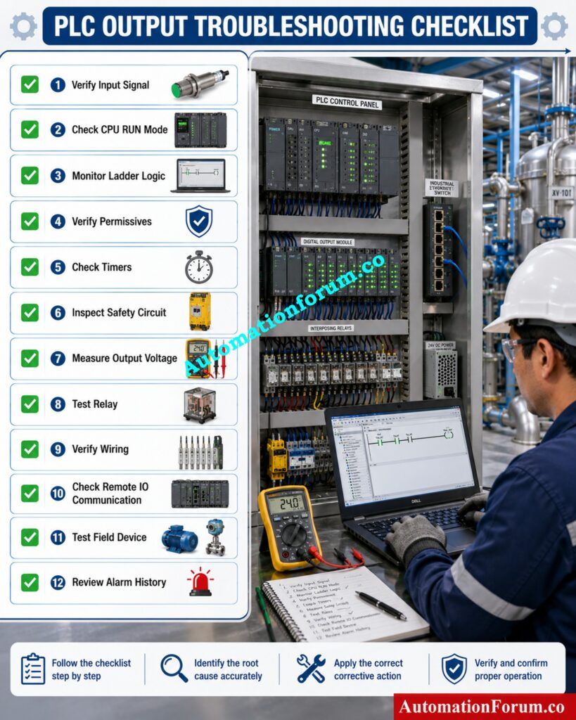
- Step by Step PLC Output Troubleshooting Procedure
- Step 1 Verify Field Input Operation
- Step 2 Check PLC Online Diagnostics
- Step 3 Monitor Ladder Logic Online
- Step 4 Verify Permissive Conditions
- Step 5 Check Timers, Counters, and Internal Memory
- Step 6 Check Emergency Stop and Safety PLC Conditions
- Step 7 Inspect the PLC Output Module
- Step 8 Check Wiring and Field Devices
- Step 9 Verify Remote I O and Communication
- Step 10 Review Alarm History and Recent Program Changes
- PLC Output Not Turning ON Root Cause Analysis Table
- Real Plant Example of PLC Input ON but Output Not Energizing
- Common PLC Troubleshooting Mistakes to Avoid
- Best Practices to Prevent PLC Output Failures
- Conclusion: Key Takeaways for Faster PLC Output Troubleshooting
- Frequently Asked Questions About PLC Output Troubleshooting
- What is the first step in diagnosing a problem with PLC inputs?
- What are the most common input/output faults in PLCs?
- What are the symptoms of a bad PLC?
- What is the most likely problem if a PLC’s output indicator is on and the output device to which it is wired is off?
- How to check PLC inputs and outputs?
- How to troubleshoot a PLC system?
- Why is my PLC input ON but the output not energising?
- How do I know if the PLC output module is faulty?
- Why does the output work in Manual mode but not in Auto mode?
- Can a safety circuit prevent a PLC output from energising?
- Why is the PLC Output LED ON but the motor does not start?
- How can online ladder monitoring help during troubleshooting?
- What should I check before replacing a PLC output module?
- Can remote I O communication faults stop PLC outputs?
- Why are voltage measurements important during PLC troubleshooting?
- What is the best way to prevent recurring PLC output failures?
Why Is the PLC Input ON but the Output Not Energizing?
Why This PLC Fault Is Common in Industrial Automation
One of the most common and aggravating PLC failures in industrial automation is when the input is ON but the output never energizes. The sensor senses the state, and the PLC input LED glows and the programming software indicates that the input is active. The motor however does not start , the solenoid valve does not shift or the contactor remains de-energized .
Why Replacing the PLC Should Never Be the First Step
This is a very common problem in oil and gas plants, chemical industries, power stations, water treatment facilities, food processing plants, pharmaceutical production and many other automated operations. The initial impulse when encountering an unexpected breakdown is to blame the PLC or change out the output module. In truth, PLC hardware is seldom the actual culprit.
When troubleshooting PLCs, follow the complete signal flow for best results, not just the controller. A systematic strategy minimizes downtime, avoids unnecessary part replacements, and helps get production back much faster.
In this guide, we will walk through the same troubleshooting process experienced automation engineers use during real plant failures.
Stop PLC Communication Failures Before They Shut Down Production: PLC Troubleshooting Remote IO Rack Communication Failure Complete Troubleshooting Guide for Industrial Automation Engineers
How Does a PLC Signal Travel from Input to Output?
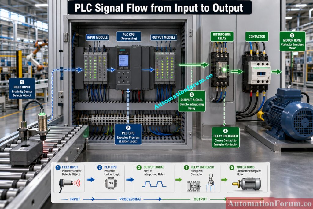
Before troubleshooting starts it is helpful to understand how a PLC processes an input signal before activating an output.
Field Input Device Operation
PLC Input Module Processing
The input module receives the field signal and converts it into a digital status that the CPU can read. A healthy input is normally indicated by both the input LED and the online monitoring screen.
Learn Industrial Mixing Logic Through Practical Ladder Programming Examples: Step-by-Step PLC Ladder Logic for Automatic Liquid Mixing Process with Interlocks
PLC Ladder Logic Processing, CPU Scan Cycle and Memory Execution
During every scan cycle, the PLC reads all inputs, executes the ladder logic, and updates the outputs. The output will energize only if every programmed condition is satisfied.
PLC Output Module Operation
Once the PLC logic approves the operation, the output module switches voltage to the field circuit. Depending on the application the signal may go through an interposing relay before it reaches a contactor, solenoid valve, alarm or other actuator. If there is a fault somewhere in this chain, the end device may not work.
Master This Documentation Method Every PLC Engineer Should Follow: PLC Alarm and Trip Documentation Procedure – EPC PLC Automation Engineer Guide
Common Symptoms of PLC Input ON but Output Not Energizing
Often engineers see one or more of the following symptoms during a PLC output failure:
- Input LED is ON.
- PLC software shows the input is active.
- Output LED remains OFF.
- Output LED is ON but the field device does not operate.
- Output works only in Manual mode.
- Output operates during testing but fails during production.
- The system is sporadic and not consistent in its operation.
Identification of these symptoms helps to narrow down the area of the malfunction before detailed troubleshooting is begun.
Avoid Programming Mistakes by Understanding PLC Resolution Completely: Resolution in PLCs – The Complete Guide for Automation & Instrumentation Engineers
Step by Step PLC Output Troubleshooting Procedure
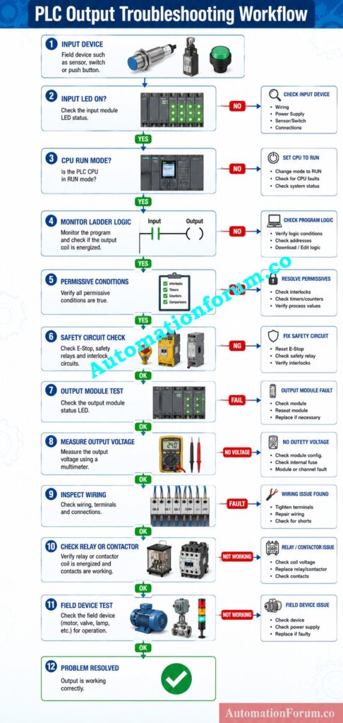
Step 1 Verify Field Input Operation
First step is to make sure the PLC is indeed getting an input signal. Run the field device and watch the input LED and the PLC diagnostics in line. Use a multimeter to measure the input voltage and compare it with the PLC requirements.
If the input status changes irregularly, check the sensor, power supply, wiring, terminal connections and input channel. Most of the time, when we see PLC output difficulties, the root cause is a bad field device or loose wiring, not the PLC itself.
Step 2 Check PLC Online Diagnostics
Verify that the input is healthy and then connect the PLC to the programming software and watch the controller online. Check that the CPU is in RUN mode, and look for any active diagnostic messages, module faults, or communication issues. Most current PLCs give thorough status information and can quickly identify a broken I/O module, watchdog malfunction, or network problem. If diagnostics show a hardware failure, troubleshoot it before proceeding.
Refer the below link for the Step-by-Step Procedure to Troubleshooting Solenoid Valves in PLC Digital Output Loops
Step 3 Monitor Ladder Logic Online
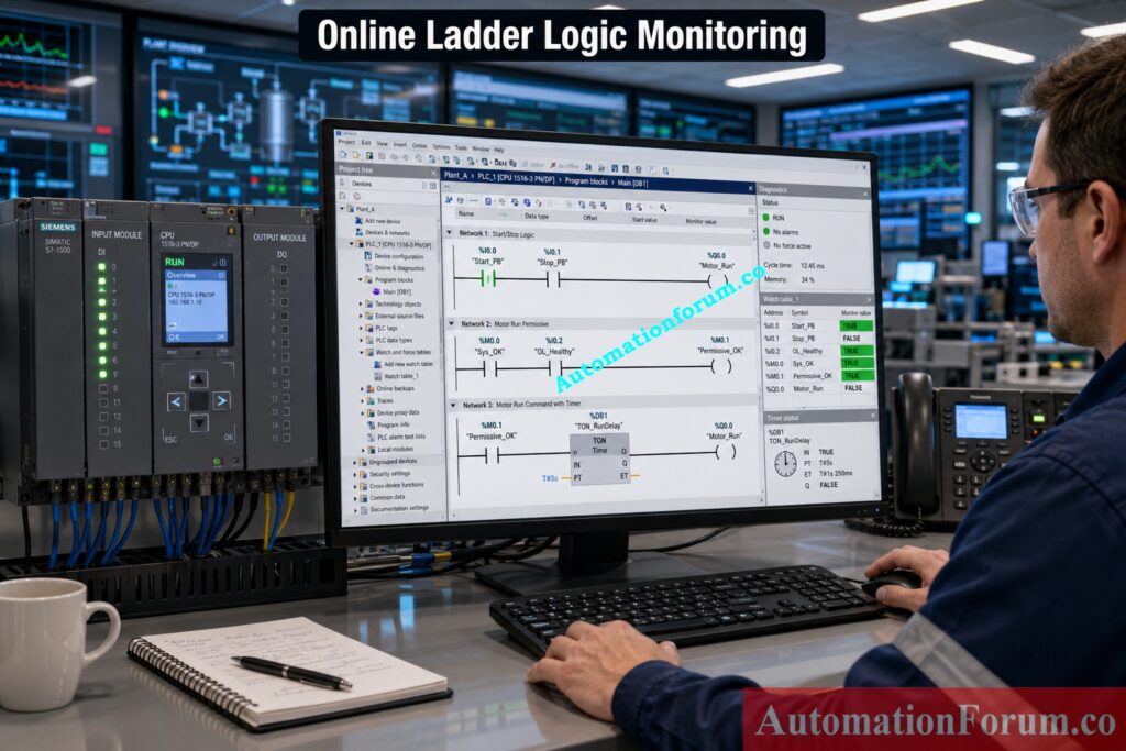
One of the fastest ways to determine the cause of a PLC output failure is to employ online ladder monitoring. Follow the logic rung that controls the output and observe which instruction is preventing the output coil from energising. A single open contact can stop the entire sequence. Monitoring the program in real time allows engineers to pinpoint the exact condition that is blocking the output.
Step 4 Verify Permissive Conditions
Most industrial equipment requires several permissive conditions before an output can operate. Common examples are motor overload connections, low pressure switches, tank level switches, guard door switches and process ready signals. Always check all interlocks before you blame a hardware failure.
Avoid Costly Logic Mistakes by Mastering Contact Selection Rules: Understanding NO vs NC Contacts is key for Logic Writing in PLC Programming
Step 5 Check Timers, Counters, and Internal Memory
Output operation is commonly controlled via timers, counters, latching bits, or internal memory flags. An output may not energise because a timer may not have finished or a counter may not have reached its preset value. Or a memory bit that has been erroneously reset may break the sequence. Compare the on-line values with the expected operation sequence to detect any anomalous condition.
Step 6 Check Emergency Stop and Safety PLC Conditions
Production orders are always subordinate to safety circuits. Confirm that the Emergency Stop circuit is OK and that all safety PLC conditions are met. The normal PLC program can appear to be OK, however the PLC output might not energise due to safety relays, door interlocks, light curtains and emergency switches.
Step 7 Inspect the PLC Output Module
If the software instructs the output and the Output LED is OFF, check the output module. Check module diagnostics, check output power supply and check any built in fuse protection. If the output channel is broken or if the supply voltage is lacking, the module will not switch appropriately.
Check the relay contacts for wear or burning for relay outputs. For transistor outputs, measure the output voltage with a calibrated multimeter and compare it with the standard given by the manufacturer.
Restore Failed Outputs Quickly with This Proven PLC Diagnostic Method: Step-by-Step Procedure for Troubleshooting PLC Digital Outputs
Step 8 Check Wiring and Field Devices
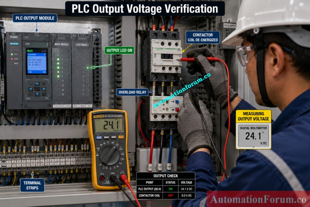
If the PLC Output LED is ON but the equipment is not responding, investigate in the field. Measure the output voltage at the PLC terminal, the interposing relay and the final actuator. Check for continuity of cables, loose connections, damaged connectors, junction boxes. Measure resistance of contactor coils, solenoid valves and relay coils for open or short circuits.
Where pneumatic or hydraulic actuators are used, verify that adequate air pressure or hydraulic pressure is available. A healthy PLC output cannot operate an actuator if the utility supply is missing.
Replace PLC Analog Cards Safely Without Causing Process Interruptions: Replacing a Faulty Analog Input Card in a PLC Rack in Continuous Process Industries: Step by Step Procedure
Step 9 Verify Remote I O and Communication
In distributed control systems, the output may be located in a remote I O rack rather than inside the main PLC cabinet. Check the communication status of Ethernet, PROFINET, EtherNet IP, Modbus TCP or PROFIBUS networks. The PLC program is running well but the remote output module may not receive commands due to failure of connectivity.
Step 10 Review Alarm History and Recent Program Changes
Finally, look at the current operating conditions, against past output records. Check alarm history, current adjustments to the program, maintenance operations, and operator reports. Many of the unexpected PLC problems occur right after software changes, wiring adjustments or equipment replacement. Many times, figuring out what changed will go directly to the core reason.
Prevent Expensive Logic Errors with These Essential PLC Data Types: PLC Data Types Every Automation Engineer Must Know to Avoid Costly Programming Errors
PLC Output Not Turning ON Root Cause Analysis Table
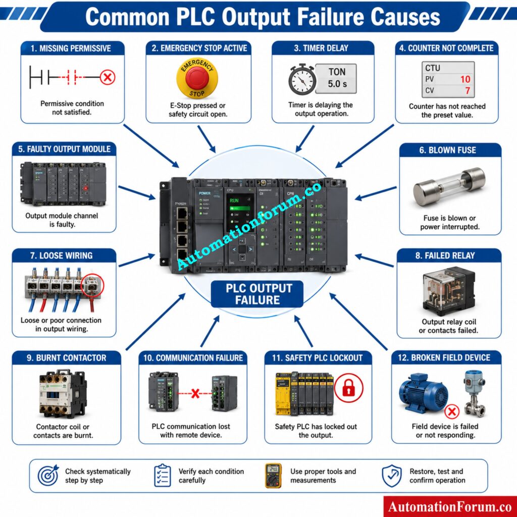
| Observed Symptom | Likely Cause | How to Verify | Recommended Solution |
| Input ON, Output OFF | Missing permissive | Monitor ladder logic | Restore permissive condition |
| Input ON, Output OFF | Emergency Stop active | Check safety circuit | Reset safety system |
| Output LED OFF | Sequence incomplete | Monitor sequence bits | Complete operating sequence |
| Output LED OFF | Timer not finished | Check timer status | Verify timer settings |
| Output LED OFF | Counter not reached | Monitor counter value | Correct process sequence |
| Output LED ON, Device OFF | Blown fuse | Measure output voltage | Replace fuse |
| Output LED ON, Device OFF | Loose terminal | Inspect wiring | Tighten terminals |
| Output LED ON, Device OFF | Failed relay | Test relay coil and contacts | Replace relay |
| Output LED ON, Device OFF | Open cable | Perform continuity test | Repair wiring |
| Output LED ON, Device OFF | Burnt contactor coil | Measure coil resistance | Replace contactor |
| Output intermittent | Loose connection | Perform vibration inspection | Secure wiring |
| Output intermittent | Unstable power supply | Measure supply voltage | Repair power source |
| Remote output inactive | Network fault | Check communication diagnostics | Restore network communication |
| Output blocked | Safety PLC fault | Review safety diagnostics | Correct safety fault |
| Output never energises | Program modification | Compare program versions | Restore validated program |
This systematic approach allows engineers to isolate faults quickly and prevents unnecessary replacement of PLC hardware.
Never Miss Critical Panel Issues During Routine PLC Inspections: Running Inspection Checklist of PLC Components in Control Panels
Real Plant Example of PLC Input ON but Output Not Energizing
First the maintenance team tested the output module and discovered no issues. PLC monitoring online revealed the start instruction was reaching the ladder logic but the output coil was not being energized. Further analysis indicated that the motor overload feedback contact had remained open from a prior overload excursion. Because this overload contact was configured as a required permissive, the PLC appropriately blocked the motor from starting.
The overload relay was reset and healthy feedback was verified, the permissive became TRUE, the PLC output energized instantly and the pump restored to normal operation.
This episode was a good lesson: the PLC was doing precisely what it was supposed to do. The actual fault was a protective device outside the PLC that was preventing unsafe operation.
Discover Why Experienced Programmers Prefer This Powerful PLC Timer: Why is RTO Used in Place of TON Timer in PLC Program?
Common PLC Troubleshooting Mistakes to Avoid
Even experienced technicians can waste valuable time by making avoidable mistakes. The following errors are among the most common during PLC fault diagnosis.
Replacing PLC Hardware Without Diagnosis
Many output modules are replaced unnecessarily when the real fault lies in field wiring, safety circuits, or program logic. Always complete systematic testing before changing hardware.
Ignoring Ladder Logic Permissives
Modern PLC programs contain numerous permissive conditions. Failing to perform these checks leads to wrong assumptions and longer downtimes.
Follow These PLC Programming Rules Every Expert Always Applies: Top 6 Important Rules for PLC Ladder Diagram Programming
Overlooking Safety Circuits
Safety PLC, guard switches, safety relays, emergency stop systems can purposefully block outputs. Never presume that the normal PLC software is the only culprit.
Skipping Voltage Measurements
The indicator lights might lie. Always use a calibrated multimeter to measure the actual input and output voltages.
Master PLC Timing Functions to Improve Process Control Accuracy: Understanding ON Delay and OFF Delay Timers in PLC Programming
Not Using Online PLC Monitoring
The offline program review does not show the real-time state of contacts, timers, counters or memory bits. With online monitoring, you’ll know right away what situation is preventing the output from activating.
Ignoring Remote IO Communication Faults
A communication fault between the PLC and remote I O rack can stop outputs even though the logic appears correct.
Missing Loose Wiring and Terminal Faults
Loose terminals, corroded connectors, and damaged cables remain some of the most common causes of intermittent PLC faults.
Forgetting to Inspect Field Devices
A failed contactor coil, solenoid valve, overload relay, or motor can produce symptoms identical to a PLC output failure. Always inspect the complete control circuit.
Choose the Right PLC Before Safety Becomes a Risk: Difference Between Standard and Safety PLCs: Features, Applications & Future Trends
Best Practices to Prevent PLC Output Failures
- Preventive maintenance drastically minimizes unplanned PLC failures and boosts plant dependability.
- Set up a routine inspection schedule for PLC cabinet, field wiring and terminal connections to discover loose/damaged components before breakdowns happen.
- Keep current backups of all PLC programs and document all software changes. Proper version management provides for a quick recovery if inappropriate program changes are introduced.
- Test relays, contactors, overload relays and solenoid valves during scheduled outages. Replacing parts before they fail reduces unnecessary production losses.
- Check PLC diagnostic logs and alarm history routinely. Small, recurring flaws are often indications of emerging problems which can be remedied before they become severe failures.
- Check power supplies and communication networks regularly, particularly in remote I/O systems. Stable power and communication are the essentials for continuous output operation.
Finally, train operators and maintenance people on a routine basis so that they are aware of the control sequence, safety interlocks and basic PLC diagnostics. A knowledgeable crew will be faster at identifying faults and restoring equipment safely.
Slash Unexpected Downtime with Smarter PLC Maintenance Practices Today: Proactive Maintenance Strategies for PLC I/O Modules: Reduce Downtime & Improve Reliability
Conclusion: Key Takeaways for Faster PLC Output Troubleshooting
A PLC input being ON but the output not energizing is not always a fault with the controller. In most industrial applications the PLC hardware itself is usually not the root reason, but rather missing permissive conditions, safety interlocks, ladder logic, field wiring, communication issues or failing actuators.
The best way to debug is to trace the signal from the device all the way back via the output module, the PLC program, and the field input. Engineers can quickly and correctly locate defects by using a combination of online ladder monitoring, electrical measurements and field inspections. A systematic troubleshooting approach and sound preventive maintenance techniques can reduce downtime and increase system reliability for maintenance teams while avoiding needless and costly replacement of PLC components.
Build Reliable Motor Control Logic with Proven Interlock Methods: PLC Program for Motor Starter with Low-Level Switch Interlock
Frequently Asked Questions About PLC Output Troubleshooting
What is the first step in diagnosing a problem with PLC inputs?
The first step is to confirm that the field input device is functioning appropriately and the PLC input LED is toggling. Check the input signal with online PLC diagnostics or a multimeter.
What are the most common input/output faults in PLCs?
Typical PLC I/O problems include bad sensors, sloppy wiring, blown fuses, broken output modules, bad relays and incorrect ladder logic. Communication difficulties and power supply issues are also common.
What are the symptoms of a bad PLC?
Typical symptoms are unresponsive inputs or outputs, CPU failure indicators, communication difficulties, unusual program behaviour and frequent system crashes. Diagnostic alerts often help identify problematic module or function.
What is the most likely problem if a PLC’s output indicator is on and the output device to which it is wired is off?
The PLC is working OK, thus the problem is likely in the field wiring, relay, contactor, solenoid valve, fuse or the output device itself. Check the whole field circuit . Measure output voltage.
How to check PLC inputs and outputs?
PLC programming software to monitor the online input and output status, measure voltages using a multimeter. Check LEDs, wiring continuity, module health, and operation of the field devices linked to it.
Create Flawless PLC Records Every Industrial Project Requires Successfully: PLC System Documentation Guide: Essential Records for Industrial Automation
How to troubleshoot a PLC system?
Troubleshoot systematically with power supplies, inputs, ladder logic, outputs, wiring, field devices, safety circuits and communication networks. Quickly follow the signal stream using online diagnostics and identify root cause.
Why is my PLC input ON but the output not energising?
Most prevalent causes are: • Lack of permissive conditions • Active safety interlocks • Timer delays • Bad ladder logic • Output module problems • Field device problems A thorough troubleshooting process will assist you determine the actual fault.
How do I know if the PLC output module is faulty?
Check the output on-line and compare it with the Output LED. If the program instructs the output but there is no voltage at the output terminal, check the module diagnostics, power supply and fuse before replacing the module.
Why does the output work in Manual mode but not in Auto mode?
Automatic mode frequently requires additional sequence criteria, sensor feedback or process permissives. Often in manual mode these conditions are skipped and the error only shows up running automatically.
Ensure Maximum Plant Availability with Advanced PLC Redundancy Design: Hot Standby in PLC Systems: Architecture, Working, and Benefits
Can a safety circuit prevent a PLC output from energising?
Yes. Emergency stop circuits, safety relays, guard switches and safety PLCs are designed to prevent output signals when there is an unsafe state.
Why is the PLC Output LED ON but the motor does not start?
The PLC has accomplished its mission well. Usually the fault is in the field wiring, the contactor, overload relay, motor starter, power supply or the motor.
How can online ladder monitoring help during troubleshooting?
The current condition of contacts, coils, timers, counters and memory bits are shown in real time via online monitoring, enabling engineers to determine the particular instruction that is stopping an output from energizing.
What should I check before replacing a PLC output module?
Verify ladder logic, safety conditions, output power supply, wiring continuity, output voltage, field device health and communication status. Do hardware replacements as a last resort only.
Can remote I O communication faults stop PLC outputs?
Verify ladder logic, safety conditions, output power supply, wiring continuity, output voltage, field device health and communication status. Do hardware replacements as a last resort only.
Why are voltage measurements important during PLC troubleshooting?
LED indications by themselves cannot verify that the field equipment is receiving the right voltage. Taking a voltage reading at each point helps you identify open circuits, blown fuses and bad components.
What is the best way to prevent recurring PLC output failures?
LED indications by themselves cannot verify that the field equipment is receiving the right voltage. Taking a voltage reading at each point helps you identify open circuits, blown fuses and bad components.
Refer the below link for the PLC Permissive Logic Troubleshooting Procedure for Instrumentation Engineers
