- What is an UP Counter?
- Key Components of an UP Counter
- Basic Operation of an UP Counter
- Example of UP Counter Description Using in Ladder Logic Program
- UP Counter in PLC Programming for Beginners
- Step by Step ladder Logic Programming an UP Counter in PLC
- Example Scenario: Counting Bottles on a Conveyor Belt
- Practical Applications of UP Counters
- What is an Up Counter in PLC?
- What is a Down Counter in PLC?
- What is the Difference Between an Up Counter and a Down Counter?
- What is the Counting Limit of a PLC Counter?
- How Does an Up Counter and Down Counter Operate in PLCs?
- What is a 4-bit Up Counter?
- What are the Types of Counters in Digital Systems?
- What is a BCD Counter?
- What is CTU in PLC Programming?
- Programmable Logic Controllers (PLCs) are integral in industrial automation for controlling machinery and processes.
- Among the various instructions available in PLCs, counters play a vital role in counting events or objects.
- There are two primary types of counters used in PLCs: UP counters and DOWN counters.
- This guide focuses on UP counters, explaining their functionality, application, and programming.
What is an UP Counter?
- An UP counter is a type of counter that increments its count value by one each time a specific event occurs.
- This event could be a sensor activation, a pulse from a button press, or any other detectable occurrence.
- UP counters are used in various applications such as counting products on a conveyor belt, tracking the number of operations, and more.
Key Components of an UP Counter
- Counter Value (CV): The current value of the counter.
- Preset Value (PV): The target value at which the counter will trigger an output.
- Count Up (CU): The input that, when activated, increases the counter value by one.
- Set Input (S): Sets the counter to the preset value when the set input ( S) is set to 1.
- Preset reached Output (D): The output that becomes active when the counter value reaches the preset value.
- Reset (R): The input used to reset the counter value to zero.
Basic Operation of an UP Counter
- Initialization: Set the preset value (PV) to the desired target count.
- Counting: Each time the count-up input (CU) is activated, the counter value (CV) increments by one.
- Output Activation: When the counter value (CV) equals the preset value (PV), the output (Q) is activated.
- Resetting: If needed, the reset input (R) can be activated to set the counter value (CV) back to zero.
Click here for Step-by-Step Guide: Converting Electrical Diagrams into PLC Programs for Industrial Automation
Example of UP Counter Description Using in Ladder Logic Program
UP Counter in PLC Programming for Beginners
Here is a basic example of how to implement an UP counter in ladder logic:
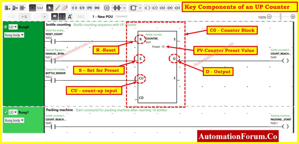
In this example:
- CU is the count-up input.
- C0 is the counter block
- D is the output that gets activated when the counter reaches the preset value.
- R is the reset input.
Step by Step ladder Logic Programming an UP Counter in PLC
Example Scenario: Counting Bottles on a Conveyor Belt
- In a bottling plant, we need to count the number of bottles passing a specific point on a conveyor belt.
- When the count reaches 10, a signal is sent to a packaging machine to start the packaging process.
Open EcoStruxure Machine Expert – Basic:
- To create and simulate a ladder diagram for an up-count operation in a bottling plant using Schneider Electric’s EcoStruxure Machine Expert – Basic, follow these steps.
- This scenario counts bottles on a conveyor belt and sends a signal to a packaging machine after every 10 bottles.
- Launch the software and open a new project or an existing one.
Click here for Step-by-Step Procedure for Creating a Ladder Diagram from Logic with Schneider Electric EcoStruxure Machine Expert Basic Software
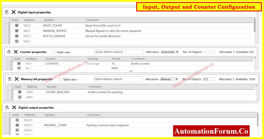
Configure Inputs:
- BOTTLE_SENSOR (%I0.2): Detects bottles passing a point on the conveyor.
- RESET_COUNT (%I0.0): Resets the bottle count.
- MANUAL_BYPASS (%I0.1): Manually bypasses the counting logic.
Configure Outputs:
- COUNT_REACHED (%M0): Indicates that 10 bottles have been counted.(Memory bit)
- PACKING_START (%Q0.1): Starts the packaging machine.
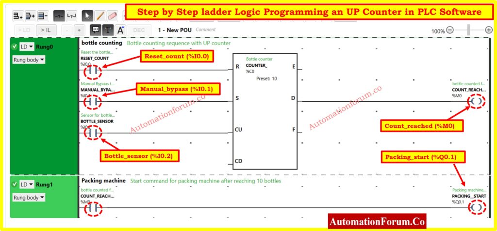
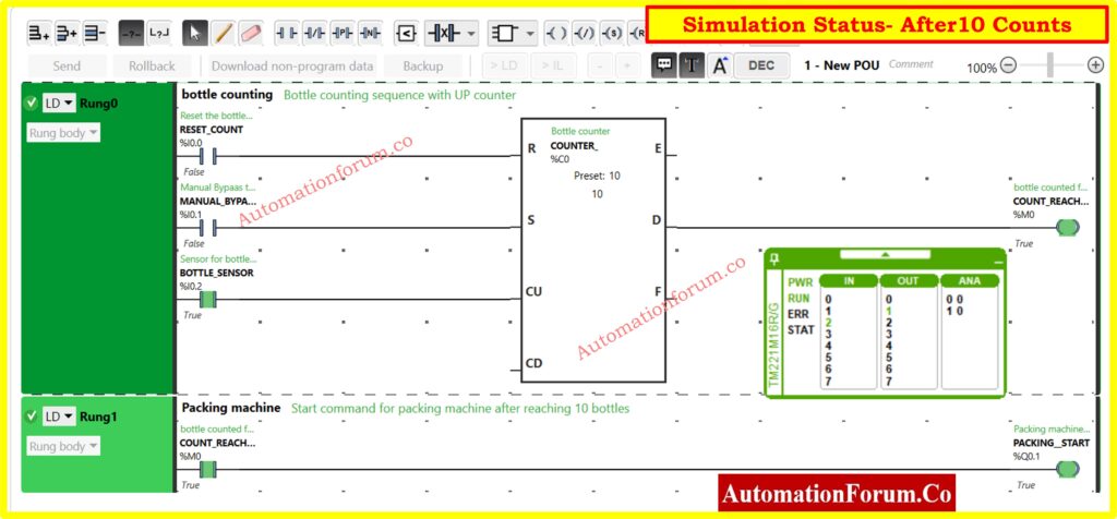
Create the Ladder Logic – Rung 0 (Bottle Counting Sequence):
- Reset the counter: Add a Normally Open (NO) contact for RESET_COUNT connected to the reset (R) input of the counter COUNTER_%C0.
- Manual Bypass: Add a Normally Open (NO) contact for MANUAL_BYPASS to bypass the counting when needed.
- Bottle Sensor: Add a Normally Open (NO) contact for BOTTLE_SENSOR connected to the Count Up (CU) input of the counter COUNTER_%C0.
- Counter Block: Add the counter block COUNTER_%C0 with a preset value of 10.
- Count Reached: Add a Normally Open (NO) contact for the counter’s output %M0 to indicate the count has reached 10.
Create the Ladder Logic – Rung 1 (Start Packaging Machine):
- Count Reached Signal: Add a Normally Open (NO) contact for %M0 to start the packaging machine when the count reaches 10.
- Packaging Machine Start: Connect this to the output coil PACKING_START (%Q0.1).
Simulation Explanation
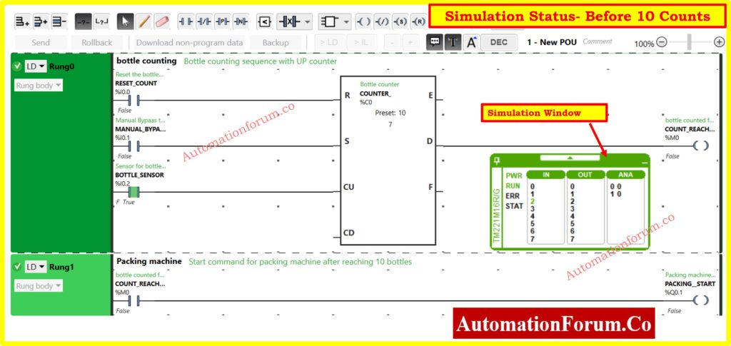
Initialization:
- When the system starts, the counter is initialized and waits for the sensor signals.
Bottle Detection:
- Each time a bottle passes the sensor, BOTTLE_SENSOR (%I0.2) sends a signal to the counter block COUNTER_%C0.
- The counter increments by one for each bottle detected.
Count Reset:
- If RESET_COUNT (%I0.0) is activated, the counter resets to zero.
Manual Bypass:
- If MANUAL_BYPASS (%I0.1) is activated, the counter logic is bypassed, and no counting occurs.
Count Reaches 10:
- Once the counter reaches the preset value of 10, the COUNT_REACHED (%M0) flag is set.
- This flag triggers the PACKING_START output coil (%Q0.1), sending a signal to start the packaging machine.
Packaging Machine:
- The packaging machine starts its operation based on the signal from the PLC.
Click here for Understanding ON Delay and OFF Delay Timers in PLC Programming
Steps in the Simulation
- Start the simulation.
- Trigger the BOTTLE_SENSOR input repeatedly until the counter reaches 10.
- Observe the COUNT_REACHED memory bit (%M0) being set to True when the count is 10.
- Verify the PACKING_START output (%Q0.1) is activated, indicating the packaging machine starts.
This setup ensures that the bottling plant counts bottles and initiates the packaging process automatically after every 10 bottles, optimizing the workflow and ensuring efficiency in the production line.
Click here for Designing 2 out of 4 Voting Logic in Control Systems: A Step-by-Step PLC Ladder Diagram Tutorial with Video
Practical Applications of UP Counters
- Production Line Counting: Counting the number of products passing a certain point on a conveyor belt.
- Machine Operation Cycles: Tracking the number of cycles a machine has completed.
- Event Monitoring: Counting specific events such as the number of times a door is opened.
Click here for More PLC Articles
Frequently Asked Questions About Up and Down Counters in PLC Programming
What is an Up Counter in PLC?
An up counter increments its count value with each input pulse until it reaches a preset limit. It is primarily used to track events or occurrences in increasing order.
What is a Down Counter in PLC?
A down counter starts counting from a predefined value and decrements with each input pulse until it reaches zero. It is used to track events in decreasing order.
What is the Difference Between an Up Counter and a Down Counter?
| Feature | Up Counter | Down Counter |
| Counting Direction | Counts from 0 to the maximum preset value. | Counts from the maximum preset value to 0. |
| Sequence | Tracks events in an increasing order. | Tracks events in a decreasing order. |
| Use Case | Ideal for counting increments or accumulations. | Suitable for counting down to specific targets. |
| Reset Behavior | Resets the count to 0 when a reset signal is given. | Resets the count to the maximum preset value. |
| Common Application | Counting items produced on a conveyor belt. | Countdown timers or inventory depletion tracking. |
What is the Counting Limit of a PLC Counter?
The counting limit of a PLC counter depends on its design. Common ranges include:
- 0 to 9999
- -32,768 to +32,767
- 0 to 65,535
The current or “accumulated” count value is typically displayed in the PLC interface during runtime.
How Does an Up Counter and Down Counter Operate in PLCs?
- Up Counter: When an input signal is received, the accumulated value increases by one.
- Down Counter: When an input signal is received, the accumulated value decreases by one.
Both counters use distinct instruction blocks in the PLC programming interface.
What is a 4-bit Up Counter?
A 4-bit binary up counter counts from 0000 (binary zero) to 1111 (binary fifteen). The inputs control the counting process, while the output is displayed as four bits, often used to drive LEDs or other indicators.
What are the Types of Counters in Digital Systems?
Counters are classified into two main types:
Synchronous Counters: All flip-flops are triggered simultaneously.
Asynchronous Counters: Flip-flops are triggered sequentially, one after the other.
What is a BCD Counter?
A Binary Coded Decimal (BCD) counter counts from 0000 to 1001 (binary representations of decimal numbers 0 to 9) before recycling back to 0000. It is commonly used in systems requiring decimal counting.
What is CTU in PLC Programming?
The CTU (Count Up) instruction in PLC programming is used to count the number of LOW-to-HIGH transitions (rising edges) of a preceding logic signal. Each time the input logic evaluates to TRUE, the Accumulated Value (ACC) increases by 1. The Preset Value (PRE) defines the maximum count, and when the accumulated value matches the preset, it can trigger specific actions or conditions. This instruction is commonly used for tracking events or counting occurrences in automation processes.