
- Overview of Profibus PA Communication Challenges
- What is Profibus PA Communication?
- How Profibus PA Communication Works
- Main Components of a Profibus PA Network
- How Profibus PA Communication Works
- Typical Profibus PA Network Architecture
- Common Symptoms of Profibus PA Communication Problems
- Root Causes of Profibus PA Communication Problems
- Step by Step Profibus PA Troubleshooting Procedure
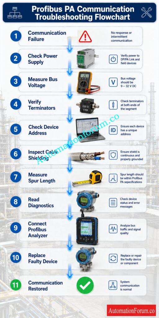
- Step 1 Verify Power Supply
- Step 2 Measure Bus Voltage
- Step 3 Check Segment Termination
- Step 4 Verify Device Addresses
- Step 5 Inspect Cable Shielding
- Step 6 Check Spur Cable Length
- Step 7 Review Diagnostic Messages
- Step 8 Test with a Profibus Analyzer
- Step 9 Isolate Faulty Devices
- Step 10 Restore Normal Communication
- Conclusion: Final Troubleshooting Recommendations
- Frequently Asked Questions (FAQs) on Profibus PA Communication Problems
- How to troubleshoot PROFIBUS communication?
- What is the problem with PROFIBUS signal?
- What is PROFIBUS PA communication?
- How to communicate with PROFIBUS?
- What are the types of PROFIBUS communication?
- What causes PROFIBUS PA devices to disappear from the network?
- Can one faulty PROFIBUS PA device affect the entire network?
- How do you check PROFIBUS PA cable health?
- Why is proper PROFIBUS termination important?
- How can PROFIBUS PA communication problems be prevented?
Overview of Profibus PA Communication Challenges
Digital field communication is widely used in the modern process industry to convey precise and reliable information between field instruments and control systems. Profibus PA (Process Automation) is one of the industrial communication protocols that enjoys a solid reputation for reliable communication in tough environments such as oil and gas, chemical plants, refineries, pharmaceutical facilities, power stations, water treatment plants and food processing industries.
Profibus PA permits many field devices to communicate on a single two wire cable. Power is supplied over the same line. Traditional 4 to 20 mA loops require separate wiring for each instrument. This considerably lowers installation costs, simplifies engineering and gives enhanced diagnostic capabilities which assist maintenance teams find problems before they cause production losses.
Even with these advantages, communication problems can still arise with Profibus PA. A transmitter may abruptly go out of the network, communication may become sporadic, alarms may flood the control room, or an entire section may cease responding. Improper diagnosis of these issues can cause production downtime, delays in commissioning procedures, increased maintenance costs and potentially plant safety issues.
One of the major issues is that communication breakdowns are often symptoms, not the cause. A device communication timeout could be caused by: inadequate cable termination, low bus voltage, too long cable runs, ground problems, moisture in the junction box, or incorrect device addressing. Simply changing the field instrument doesn’t often address the root problem.
Experienced instrumentation engineers know that debugging Profibus PA networks is not always easy. They check the health of power supplies . Look at the physical wiring . Check the quality of communications . Review diagnostics from the host system . Work at isolating the fault one step at a time . Instead of assuming . This systematic approach saves time during troubleshooting and minimizes unnecessary equipment replacement.
In this practical book you will discover how Profibus PA communication works, analyze the architecture of a typical network, spot the early warning signs of communication difficulties and establish a solid foundation for effective troubleshooting in real industrial applications.
Master Intrinsically Safe Fieldbus Design Without Expensive Engineering Mistakes: Fieldbus Intrinsically Safe Concept (FISCO) Model for Foundation Fieldbus H1 and Profibus PA
What is Profibus PA Communication?
Definition of Profibus PA
Profibus PA (Process Automation) is a global standard digital communication protocol for process industries. It enables intelligent field devices such as pressure transmitters, temperature transmitters, flow meters, level transmitters, valve positioners and analyzers to connect with a Distributed Control System (DCS) or Programmable Logic Controller (PLC) across a common communication network.
Advantages of Profibus PA Over 4-20 mA Systems
Refer the below link for the Profibus Segment Calculator for DP and PA Network Design
How Profibus PA Communication Works
Manchester Bus Powered (MBP) Technology
The physical layer of Profibus PA employs Manchester Bus Powered (MBP) technology. In this communication method, digital data is transmitted together with DC power over the same cable.
How Data and Power Share the Same Cable
This technology provides several practical benefits for industrial applications.
- Simpler installations with fewer cords.
- Can provide longer range of communication.
- Intrinsic safety barriers facilitate hazardous area installations.
- It also makes maintenance easier because there are fewer connections to inspect.
The same cable is used to carry the communication signals as well as the electrical power, hence it is important to maintain proper voltage, cable quality, shielding and termination for reliable operation.
Test Your Industrial Communication Knowledge Before Your Next Interview: PROFIBUS Quiz: Top 25 Advanced Interview MCQs with Answers for Automation Professionals
Main Components of a Profibus PA Network
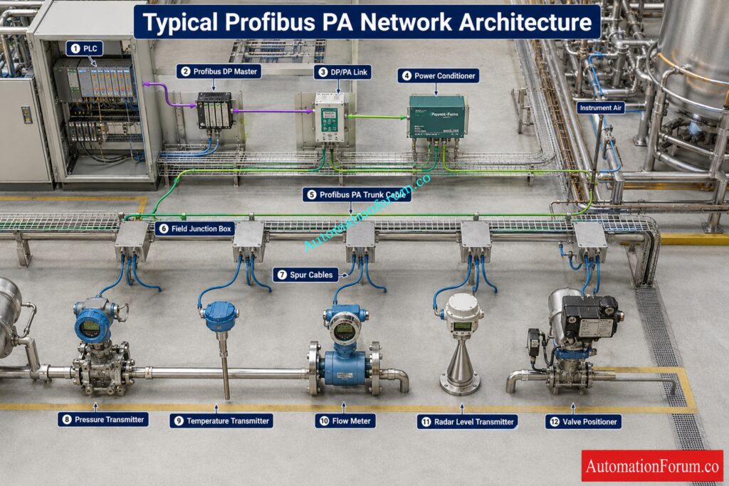
The standard Profibus PA system consists of several key components working together to enable reliable communication within the process plant.
Host System
DP PA Link or Segment Coupler
Most control systems communicate using Profibus DP. Field instruments interact through Profibus PA. In such a case a DP PA Link or Segment Coupler functions as a communication bridge between these two networks, translating messages and assuring data integrity.
Power Conditioner
The power conditioner isolates communication signals from the power source and injects stable DC power into the communication wire. It also aids in maintaining signal quality throughout the segment.
Trunk Cable
The trunk cable is the backbone of Profibus PA network. This disperses communication and electricity from the control center to field junction boxes that are distributed throughout the facility.
Spur Cable
The individual field devices are connected to the trunk via shorter spur cables. Keeping the spur length within suggested limits ensures good communication quality and reduces signal deterioration.
Field Devices
A Profibus PA network may contain many different intelligent instruments such as pressure transmitters, differential pressure transmitters, temperature transmitters, flow transmitters, radar level transmitters, valve positioners, analytical instruments and intelligent actuators.
Each device has a unique address which allows the controller to “know” the device and communicate information without interference to other devices on the network.
Crack Tough Automation Interviews Using Proven Expert Question Sets: Profibus Interview Questions and Answers
How Profibus PA Communication Works
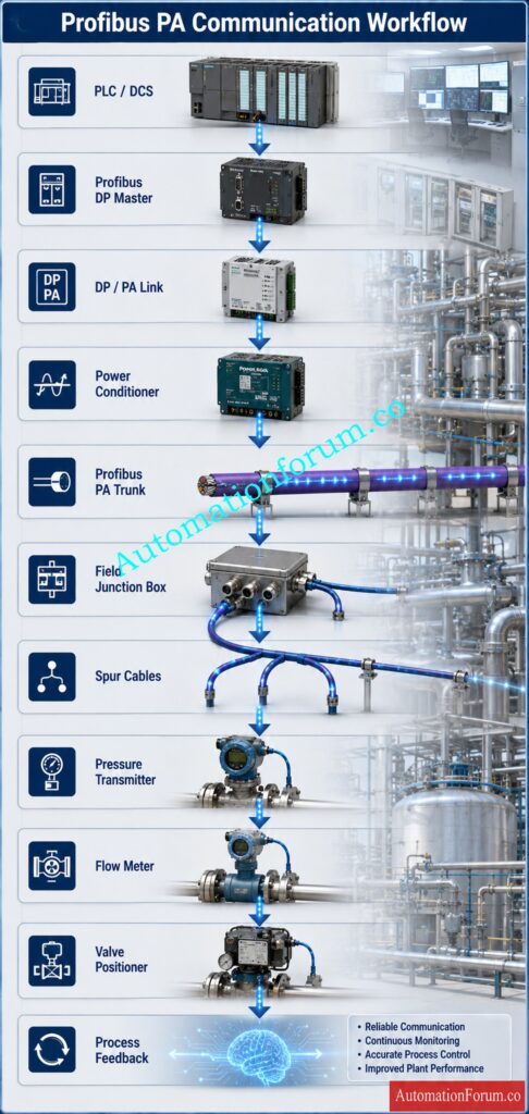
If you understand how Profibus PA communication works, it makes debugging a lot easier, because engineers can see where the communication is breaking down.
Unlike the continuous transmission of a single current value in classic analog systems, Profibus PA communicates structured digital information between the controller and several field instruments.
The communication process is a systematic sequence.
Choose The Right Communication Protocol For Maximum Plant Reliability: Difference Between Fieldbus and HART Communication Protocols:
Controller Initiates Communication
The PLC or DCS talks with the Profibus DP Master which controls all communication on the network. The master decides which field device should communicate and when that communication takes place.
Since only one master controls communication, data collisions are prevented and network performance remains stable.
DP PA Link Transfers Information
The DP PA Link converts high speed Profibus DP communication into the lower speed communication format used by Profibus PA field devices.
This conversion occurs automatically and is completely transparent to operators.
Polling of Field Devices
The master communicates with every device one at a time.
For example, it may communicate with a pressure transmitter first, followed by a temperature transmitter, then a flow meter, and finally a valve positioner.
No instrument is played unless the maestro calls for it. This well ordered polling sequence guarantees well ordered communication over the whole network.
Cyclic Communication
During regular operation of the plant, cyclic communication is exchanging vital process information such as process variable values, device status, operating conditions, output values and alarm information.
This message is repeated continually in milliseconds, allowing the operators to watch the process in real-time.
Acyclic Communication
Also acyclic communication is supported by Profibus PA, which is usually used for engineering and maintenance.
Examples include parameter modification, calibration settings, configuration updates, diagnostic information, and firmware details.
Maintenance engineers frequently use engineering software to access this information during commissioning, troubleshooting, and preventive maintenance.
Device Diagnostics
One of the greatest advantages of Profibus PA is its advanced built in diagnostic capability.
Instead of only reporting a communication fault, intelligent devices can provide detailed diagnostic messages such as sensor failure, electronics malfunction, maintenance required, process alarm, simulation mode active, configuration mismatch, or excessive internal temperature.
These detailed diagnostics help maintenance personnel identify problems much faster and reduce unnecessary field visits.
Learn The Core Technology Every Instrument Engineer Must Understand: What is Profibus and what is its application in Instrumentation?
Typical Profibus PA Network Architecture
Communication Flow
A reliable Profibus PA network depends on the correct installation and operation of several interconnected components.
Segment Layout
The standard plant network has a PLC or DCS that controls the process and connects with field instrumentation. An engineering workstation is used for configuration, diagnosis, calibration and service.
The Profibus DP Master controls the communication timing and sequentially polls each field device. The DP PA Link or Segment Coupler links the Profibus DP network to the Profibus PA segment and converts the communication protocols.
Power Distribution
The network is powered by a steady electrical power source, and the power conditioner supplies this power to the communication line without altering the signal integrity.
Engineering Workstation
The trunk cable is the main communication link through out the plant. Communication is distributed from junction boxes along the trunk to several spur cables connecting various field equipment such as transmitters, valve positioners, analyzers and intelligent actuators.
Common Installation Practices
All Profibus PA segments have terminators at each end of the segment. These are designed to prevent signal reflections and to make communications stable. Incorrect or missing termination is one of the most common causes of communication failures in industrial plants.
When every component is correctly designed, installed, and commissioned, a Profibus PA network can operate reliably for many years. However, even a slight installation problem, such as insufficient bus voltage, broken cable insulation, duplicate device addresses, weak terminal connections, or poor shielding, might impact communication throughout the entire segment.
A good grasp of this architecture provides a basis for rapid and effective diagnosis of communication difficulties during commissioning, normal maintenance and plant shutdown activities.
Discover Critical Protocol Differences That Impact Every Automation Project: Difference between profibus and foundation field bus
Common Symptoms of Profibus PA Communication Problems
The first step in avoiding long-term plant downtime is to identify early indicators of communication issues. Often a communication problem begins with subtle warning indications, before becoming a full network failure. These symptoms are closely watched by experienced nstrumentationi engineers, because they often provide clues about the source of the problem.
Devices Suddenly Disappear from the Network
Intermittent Communication
Intermittent communication is usually more difficult to diagnose than a complete communication loss. Devices may run normally for hours then randomly go off line and come back on line without interaction.
Loose terminals, moisture in junction boxes, broken insulation, insufficient shielding, electrical interference, and unstable power sources can all cause such behavior. Temperature and vibration of the equipment can also contribute to the worsening of intermittent problems, which may only arise under certain operating conditions.
Communication Timeout Alarms
If the controller does not receive a reply from a field device within the time it expects, a communication timeout alarm is raised. Communication failure warnings may appear on the DCS and process values may be frozen or incorrect.
Timeout alerts are usually caused by long cable lengths, poor signal quality, wrong network configuration, overcrowded communication segments, or electronic components in the field instruments that are deteriorating.
Eliminate Communication Errors Using This Powerful HART Calculation Tool: Advanced HART Loop Calculator for Reliable 4 to 20 mA and HART Communication
Slow Process Value Updates
Process values are sometimes observed to update substantially more slowly than predicted by operators. Communication is still ongoing, however there are delays in pressure, temperature or flow on the operator screen.
Slow communication may indicate excessive network loading, configuration errors, incorrect polling parameters, or communication retries caused by signal corruption.
Poor Quality Process Values
Modern control systems assign quality information to every transmitted process variable. When communication quality decreases, the controller may flag values as uncertain, bad, or invalid.
Poor quality values should never be ignored because they often indicate developing communication problems that may soon become complete failures.
Improve Signal Reliability Using Proven Industrial Cable Selection Techniques: Twisted Pair Cable in Industrial Signal Transmission: The Essential Guide for 4-20 mA and RS 485 Systems
Frequent Device Restart
Some field instruments repeatedly restart themselves while remaining connected to the network. Operators may observe communication interruptions every few minutes before the device returns to service.
This symptom generally implies lack of operating voltage, unreliable power supplies, over-current consumption or internal electrical defects.
Engineering Software Cannot Access Devices
The process value will still be displayed in the DCS, but the engineering workstation will not be able to upload parameters, perform diagnostics, or establish online communication with a device. Maintenance engineers may discover this.
Often this problem is caused by incompatibilities in setup, incompatible device descriptions, inaccurate addresses or conflicting communication parameters.
Network Instability After Adding a New Device
It is not uncommon for a communication network that has worked reliably for years to suddenly become unstable after installing a new transmitter or valve positioner.
In many cases, the newly installed device increases current consumption beyond the available power margin, introduces duplicate addresses, exceeds allowable spur lengths, or contains incorrect configuration settings.

Root Causes of Profibus PA Communication Problems
Every communication failure has an underlying cause. Successful troubleshooting depends on identifying the actual source instead of replacing equipment unnecessarily.
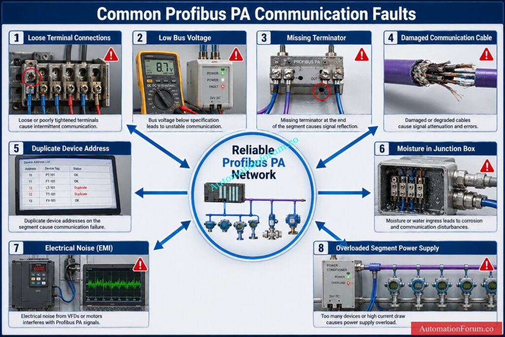
Incorrect Network Termination
Incorrect termination remains one of the most common installation mistakes.
Profibus PA requires proper termination at both ends of every communication segment. If terminators are missing , broken , or improperly fitted , they can cause signal reflections that distort communication signals .
- Typical Symptoms: Random device disconnections from the network, inconsistent communication and many instruments with sporadic alarms.
- Diagnosis: How to Check the position of the two terminators, check their installation and measure the bus voltage using an appropriate fieldbus tester.
- Corrective Action: Replace bad terminators and ensure that termination is only at the two ends of the section.
- Prevention: Check termination on commissioning and after any network changes.
Wrong Profibus PA Cable Selection
Profibus PA requires communication wire that is specifically designed for fieldbus applications.
Standard instrument cable might cause higher signal attenuation, worse communication quality and voltage drop issues over extended distances.
- Typical symptoms: communication faults will rise with connection length, and distant devices may fail before devices close by.
- Diagnosis: Verify the installed cable parameters against the Profibus installation instructions.
- Corrective Action: Replace the unacceptable cables with an approved Profibus PA communication cable.
- Prevention: Identify the certified fieldbus cable already at project engineering phase.
Loose Terminal Connections
Loose terminals are a typical cause of occasional communication failures.
The contact resistance will grow gradually with vibration, thermal expansion, poor tightness and aging terminals, resulting in unreliable communication.
- Symptoms: The communication is normal and then just stops working when the equipment is vibrating or when the ambient temperature changes.
- Diagnosis: Check all terminals in junction boxes, marshalling cabinets, field devices and power conditioners.
- Corrective Action: Tighten connections and replace broken terminal blocks as required.
- Prevention. Incorporate terminal inspection into preventive maintenance plans.
Low Bus Voltage
For Profibus PA devices to function properly, they require sufficient operating voltage.
The more devices on the section, the voltage slowly drops due to resistance of the cable and the current draw.
Communication becomes inconsistent when the voltage drops below the minimum operational requirement.
- Symptoms: Devices restart unexpectedly, disappear from the network, or fail during startup.
- Diagnosis: Check the bus voltage at the power conditioner and at the furthest field device.
- Corrective Action: Reduce the segment loads, reduce cable lengths if possible, update the power supply or add more segments.
- Prevention: Perform voltage drop calculations during network design, not after commissioning.
Duplicate Device Addresses
Every Profibus PA instrument must have a unique address on the network.
When two devices have the same address, the controller can’t tell them apart and communication conflicts occur.
- Symptoms: One or both instruments disappear, transmission is unstable or device information is wrong during diagnosis.
- Diagnosis: Run engineering software to scan all device addresses.
- Corrective Action: Assign a unique address to each device and download the new configuration.
- Prevention: Keep accurate paperwork every time devices are added or removed.
Moisture and Water Ingress
Moisture ingress to junction boxes, cable glands or field instruments is a typical cause of communication failure in outdoor systems.
Water can reduce insulation resistance and corrode internal connectors and terminals.
- Symptoms: Communication breaks down after heavy rain fall or during excessive humidity.
- Diagnosis: Check cable glands, junction boxes and connectors for evidence of dampness or corrosion.
- Corrective Action: Dry affected components, replace any broken terminals, enhance sealing and fit correct weatherproof cable glands.
- Prevention: Regularly check and repair defective seals before entry of water begins.
Electrical Noise and Electromagnetic Interference
Variable frequency drives, powerful motors, welding equipment and high voltage cables all give off electromagnetic interference which if proper cable routing and shielding is not done can damage the quality of communications.
- Symptoms: When electrical equipment in the vicinity is started or stopped communication errors rise.
- Diagnosis: Verify cable routing, shielding procedures and grounding systems.
- Corrective Action: Separate communications wires from power cables. Improve shielding continuity. Correct faulty grounding.
- Prevention: Follow specified installation practices when routing cables and when expanding the plant.
Segment Power Supply Overload
Each Profibus PA section has a maximum current carrying capability.
Adding other instruments without re-calculation of the power usage could overload the power conditioner.
Symptoms: Several gadgets disappear simultaneously, especially during startup when the current draw is at its maximum.
Diagnosis: Calculate the total current draw of each device connected.
Corrective Action: Add more segments or update the power conditioner to handle the additional load.
Prevention: Always check power margins before installing new field equipment.
Compare Modern Configuration Tools Before Investing Your Valuable Time: SmartBlue vs HART Communicator: Which Is Better for Instrumentation Engineers?
Step by Step Profibus PA Troubleshooting Procedure

Step 1 Verify Power Supply
Start by examining the DC voltage supplied by the Profibus PA power conditioner to the segment. Verify the status of the power supply, the output voltage, the fuses and the wiring connections. If you have an unstable or failing power source, several devices can go down simultaneously.
Step 2 Measure Bus Voltage
Measure the bus voltage at the power conditioner and at the farthest field device with a calibrated multimeter or fieldbus tester. Compare measured values to device manufacturer specs. A large voltage drop suggests excessive cable resistance, overloaded sections, or faulty electrical connections.
Prevent Commissioning Problems With Proven Fieldbus Installation Techniques: Foundation Fieldbus Installation and Best Practices – Complete Guide for EPC and Maintenance Engineers
Step 3 Check Segment Termination
Ensure that exactly two terminators are inserted, one at each end of the Profibus PA section. Missing , broken or misplaced terminators cause signal reflections which leads to intermittent communication , timeouts and unreliable device operation .
Step 4 Verify Device Addresses
Use the engineering tool to scan the network and make sure that each Profibus PA device has a unique address. Duplicate addresses can prohibit the DP master from interacting properly, and can cause devices to disappear or send inaccurate diagnostic information.
Step 5 Inspect Cable Shielding
Inspect communication cables for damaged insulation, loose shield connections, poor grounding, moisture penetration or route near high voltage power lines. Proper shielding and grounding reduce electromagnetic interference and enhance communication dependability.
Step 6 Check Spur Cable Length
Measure the length of each spur cable and verify that it is within the Profibus PA installation parameters. In big process plants, long spur cables can increase signal attenuation and deteriorate communication quality.
Step 7 Review Diagnostic Messages
Access diagnostics from the PLC, DCS, or engineering workstation. Check alarms, device status, communication error counts, maintenance alerts and manufacturer specific diagnostic messages . Such diagnostics will frequently discover the defect faster than physical inspection alone.
Step 8 Test with a Profibus Analyzer
Step 9 Isolate Faulty Devices
If the problem persists, disconnect questionable devices one at a time and evaluate the network performance. A single malfunctioning transmitter, valve positioner or field device with an internal short circuit or with an excessive current consumption can disturb the whole communication segment.
Step 10 Restore Normal Communication
Once the discovered fault has been corrected, reconnect all devices, test stable communication throughout the segment, confirm the clearing of alerts, and ensure that each field equipment is reacting normally. Record underlying cause, corrective action, and test results to enable future maintenance and improve long-term network dependability.
Optimize Modbus Communication Performance By Selecting The Correct Baud Rate: Key Factors to Consider When Setting Baud Rate in Modbus Networks
Conclusion: Final Troubleshooting Recommendations
These symptoms and core causes are the basis for systematic troubleshooting. Instead of replacing the transmitters right once, professional engineers will check the quality of the transmission, visually analyze the network, evaluate diagnostics and eliminate possible reasons one by one. This organized technique reduces downtime, lowers maintenance costs and restores dependable Profibus PA connectivity considerably faster than trial and error methods.
Upgrade Your Automation Knowledge With Next-Generation Ethernet Technology: Ethernet-APL (Advanced Physical Layer): Practical Guide for EPC Instrumentation & Process Automation Engineers
Frequently Asked Questions (FAQs) on Profibus PA Communication Problems
How to troubleshoot PROFIBUS communication?
First of all verify the power supply, the termination of the cable, the bus voltage and the device addresses. Then utilize engineering software or a PROFIBUS analyzer to locate communication faults and defective devices.
What is the problem with PROFIBUS signal?
The most typical causes of PROFIBUS signal difficulties include bad termination, broken cables, weak connections, electrical noise and low bus voltage. This can cause communication difficulties, intermittent failures or total network breakdowns.
What is PROFIBUS PA communication?
PROFIBUS PA is a digital fieldbus communication standard for process automation where power and data are transmitted over the same two wire cable. It links smart field instrumentation to PLC or DCS systems for dependable process control.
How to communicate with PROFIBUS?
The communication with PROFIBUS is done via a PLC, DCS or engineering workstation connected via a PROFIBUS DP Master and DP PA Link. Configuration software allows to monitor equipment, change parameters or run diagnostics
What are the types of PROFIBUS communication?
There are two major varieties of PROFIBUS DP (Decentralized Peripherals) for high speed industrial automation and PROFIBUS PA (Process Automation) for intelligent field instruments in process industries.
What causes PROFIBUS PA devices to disappear from the network?
Low bus voltage, duplicate addresses, bad termination, damaged connections or power supply difficulties might cause devices to go missing. Systematic network examination allows rapid identification of the specific reason.
Can one faulty PROFIBUS PA device affect the entire network?
Yes, a bad device with an internal short or too much current draw can interrupt communication on the entire section. You can isolate the instruments one at a time and find the bad instrument.
How do you check PROFIBUS PA cable health?
Check for physical damage, moisture, loose terminals and wrong shielding of the cable. A fieldbus analyzer measuring bus voltage and signal quality provides a better picture.
Why is proper PROFIBUS termination important?
Proper termination prevents signal reflections which can corrupt communications and cause periodic network outages. At each end of a PROFIBUS PA section, two terminators must be installed.
How can PROFIBUS PA communication problems be prevented?
Adhere to prescribed installation techniques, using certified fieldbus cables, ensure correct grounding and shielding, and conduct regular preventative maintenance. Routine diagnostics can catch problems in the making before they affect productivity.
Refer the below link for the Avoid Unexpected Plant Shutdowns Caused By Simple Addressing Mistakes
