
- Introduction to Common Reasons for RTD Failures
- What Is an RTD and How Does It Work?
- Why RTDs Fail in Industrial Applications
- Common RTD Failure Modes Causes Impact and Recommended Solutions
- Common Reasons for RTD Failures
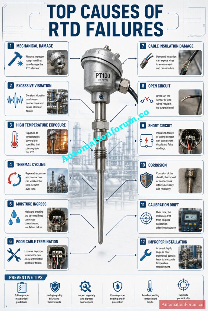
- Mechanical Damage During Installation or Maintenance
- Excessive Vibration Damage
- High Temperature Exposure
- Thermal Cycling Effects on RTDs
- Moisture Ingress and Water Penetration
- Poor Cable Termination and Loose Electrical Connections
- Cable Insulation Damage
- Open Circuit and Short Circuit Failures
- Corrosion and Chemical Attack
- Improper Installation and Wrong Insertion Depth
- Calibration Drift and Sensor Aging
- Improper Extension Cable Selection
- Symptoms of a Failing RTD
- Step by Step RTD Troubleshooting Procedure
- Best Practices to Prevent RTD Failures
- Real Industrial Example of RTD Failure Diagnosis
- Conclusion on Common Reasons for RTD Failures
- Frequently Asked Questions About RTD Failures
- What causes RTD failure?
- What are the three common causes of sensor failure?
- How to troubleshoot a faulty RTD?
- What causes a thermocouple to fail?
- What is the most common thermocouple failure method?
- How to diagnose a faulty thermocouple?
- Why do RTDs fail?
- How can I test an RTD?
- What causes RTD drift?
- Can vibration damage an RTD?
- How often should RTDs be calibrated?
- Can moisture affect RTDs?
- What resistance should a healthy PT100 show?
- What is the difference between cable failure and sensor failure?
- When should an RTD be replaced?
Introduction to Common Reasons for RTD Failures
Resistance Temperature Detectors (RTDs) are widely used in process sector due to their superior accuracy, repeatability and long term stability. RTDs find use in many applications such as refinery heaters, pharmaceutical reactors, power plant boilers, food processing lines, and water treatment facilities. Whatever the application, the RTD is a vital part in ensuring safe and efficient process temperatures.
RTDs are built for harsh industrial conditions, yet they can, and do, fail. Plant engineers often meet unexpected temperature variations, sporadic readings or full sensor failures that result in wasteful shutdowns, product quality difficulties and maintenance expenditures. The sensor itself is often not the real problem. This is usually caused by incorrect installation, broken wiring, entry of moisture, vibration or inadequate maintenance methods.
A good understanding of common RTD failure causes can assist maintenance personal detect problems immediately, increase measurement reliability, save down time and extend the life of the sensor. In this post we will present the most frequent reasons of failure, realistic troubleshooting procedures and proven preventive strategies from real industry experience.
Think You Master Sensor Selection? Prove Your Engineering Skills: Quiz on RTD and Thermocouple Selection for Instrumentation Design Engineers
What Is an RTD and How Does It Work?
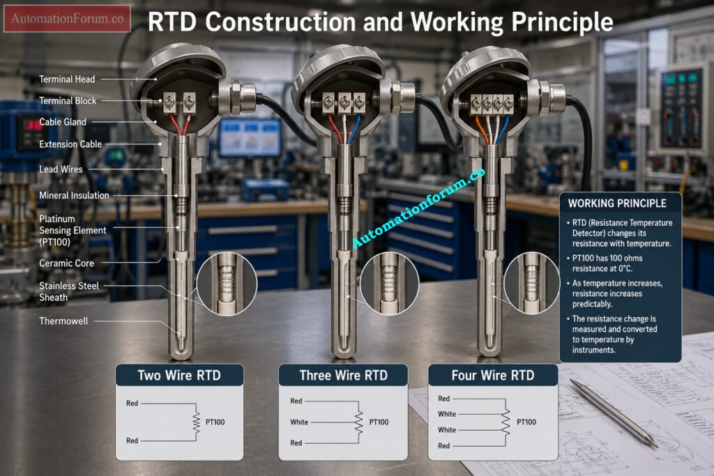
What Is a Resistance Temperature Detector
A Resistance Temperature Detector (RTD) is a temperature sensor based on the change of electrical resistance of a metallic sensing element.
Platinum RTD Working Principle
Platinum is the preferred material because its resistance changes in a highly predictable manner over a wide temperature range.
The most widely used industrial sensor is the PT100, which has a resistance of 100 ohms at zero degrees Celsius. PT1000 sensors are also common where higher signal sensitivity is required.
Industrial RTDs are generally available in three wiring configurations.
Two Wire RTD
The simplest arrangement where lead wire resistance directly affects measurement accuracy. It is normally used only for short cable runs.
Never Misconfigure Temperature Transmitters During Critical Plant Commissioning: How to Calibrate RTD transmitter?
Three Wire RTD
The most common industrial configuration. It compensates for lead resistance and provides accurate measurements for PLC, DCS, and temperature transmitters.
Four Wire RTD
Used for laboratory measurements and critical industrial applications requiring the highest possible accuracy by eliminating lead wire resistance errors.
Common Industrial Applications of RTDs
Why RTDs Fail in Industrial Applications
Environmental Factors Affecting RTD Performance
Despite their reputation for reliability, RTDs operate in some of the harshest industrial environments. Extreme temperatures, vibration, chemicals, moisture, pressure, and mechanical handling gradually affect sensor performance.
Mechanical and Electrical Causes of RTD Failure
From field experience, manufacturing defects account for only a small percentage of failures. Most problems develop after installation because of poor cable practices, damaged thermowells, incorrect sensor selection, improper maintenance, or harsh process conditions. Understanding these failure processes might help engineers avoid sudden shutdown and increase the dependability of the measurement in the long term.
Only Experienced Engineers Can Score High on This Challenge: RTD (Resistance Temperature Detector) Advanced Quiz
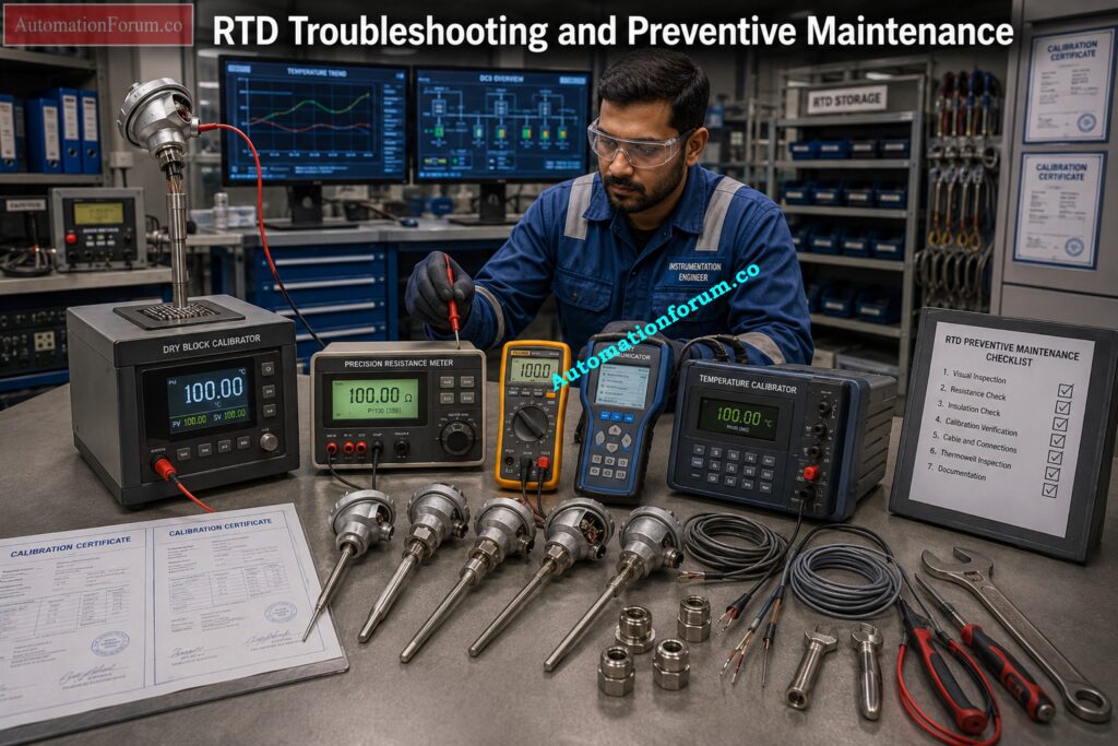
Common RTD Failure Modes Causes Impact and Recommended Solutions
| Common RTD Failure | Likely Cause | Impact | Recommended Solution |
| Open circuit | Broken sensing element or cable | No temperature reading | Replace sensor and inspect wiring |
| Short circuit | Moisture or damaged insulation | Incorrect low temperature reading | Repair wiring and eliminate moisture |
| Calibration drift | Aging or overheating | Reduced measurement accuracy | Recalibrate or replace RTD |
| Moisture ingress | Failed cable gland or junction box seal | Unstable readings | Improve sealing and replace damaged components |
| Mechanical damage | Mishandling or excessive force | Sensor failure | Install carefully and protect during maintenance |
| Cable damage | Abrasion or crushing | Intermittent signal | Replace damaged cable and improve routing |
Refer the below link for the RTD Callendar–Van Dusen Calculator | Accurate PT100, PT500, and PT1000 Conversion
Common Reasons for RTD Failures
Mechanical Damage During Installation or Maintenance
One of the most frequent reasons for RTD failure is still mechanical damage. Sensors are routinely bent, dropped, struck with tools or shoved into thermowells during installation.
During plant outages, maintenance personnel often pull numerous temperature sensors for inspection. RTDs can be dropped on hard surfaces, walked on, or otherwise destroyed during transport in busy turnaround schedules.
Symptoms
- Readings intermittently
- Total sensor failure
- Alarms open circuit
- Fluctuating resistance values
Diagnosis
Check the sensor sheath for dents, bends, cracks or impact marks. Compare the sensor’s resistance to conventional RTD values.
Prevention
RTDs should always be treated with care, stored with protective covers, and never forced into a thermowell that may have debris or corrosion.
Replace Failed Temperature Sensors Safely Without Costly Shutdown Mistakes: Faulty Thermocouple Replacement Procedure in Process Area: Complete Step-by-Step Field Guide for Instrumentation Engineers
Excessive Vibration Damage
Constant vibration from compressors, pumps, turbines, cooling fans, and large motors can slowly damage the sensing element or internal connections.
Long insertion lengths without proper mechanical support are particularly susceptible to vibration caused fatigue.
Refinery engineers might see temperature values that only change when a nearby compressor is running. Upon inspection, the RTD sheath may look intact with the interior sensing element having shattered from extended vibration.
Symptoms
- (occasional) temperature changes
- Different ways of reading
- Alarms open circuit from time to time
Diagnosis
Compare sensor performance during equipment operation vs. shutdown. Examine the thermowell for wear due to vibration or for fatigue cracks.
Prevention
Select vibration resistant RTDs, use properly designed thermowells, and avoid unnecessarily long insertion lengths.
Stop Cable Selection Mistakes That Cause Unreliable Temperature Readings: Thermocouple Wire vs. Thermocouple Extension Wire: The Complete Guide for Instrumentation Engineers
High Temperature Exposure
Every RTD has a maximum operating temperature specified by the manufacturer. Continuous exposure beyond this limit gradually changes the characteristics of the platinum sensing element.
Overheated RTDs commonly develop calibration drift before complete failure occurs. Process temperature above the specified limits can cause damage to the sensor and often results in unnecessary transmitter replacement by maintenance personnel.
Symptoms
- The temperature readings start to move slowly.
- Calibration mistakes increase
- The quality difficulties of product arise
Diagnosis
Compare calibration findings to prior maintenance records and review process temperature history.
Prevention
Always select an RTD with the correct temperature rating and with enough safety factor for the process.
The Critical Compensation Principle Every Instrument Engineer Must Understand: Why Thermocouple Reference Junction Compensation(CJC) is Essential for Accurate Temperature Measurement ?
Thermal Cycling Effects on RTDs
The sensing element, mineral insulation and protective sheath, expand and contract with repeated heating and cooling.
During normal operation of power plants, batch reactors, sterilizers and food processing systems, RTDs are often subjected to rapid temperature changes.
Internal welds will eventually deteriorate with repeated temperature cycling, increasing the chance of open circuit failures.
Symptoms
- Gradual calibration shift
- Intermittent measurement errors
- Reduced repeatability
Diagnosis
Check the operating history to see if the process is subject to frequent heating and cooling cycles.
Prevention
Select RTDs specifically developed for cyclic service and limit temperature shock during plant start-up.
Moisture Ingress and Water Penetration
One of the most neglected reasons for RTD failure in industrial operations is moisture ingress to junction boxes, cable glands or terminal heads.
Damaged cable glands allow water to enter the terminal compartments during the monsoon seasons or equipment washdowns. Moisture reduces insulation resistance, creates leakage currents, and leads to unstable measurements or total sensor failure.
Outdoor RTDs commonly fail in water treatment plants because cable entrances are not securely sealed after commissioning.
Symptoms
- Variable temperature indicator
- Sudden shifts in reading
- Intermittent alarms of communication
- Low insulating resistance.
Diagnosis
Examine junction boxes for dampness, corrosion, or the presence of water. Test for moisture contamination by doing insulation resistance testing.
Prevention
Use good quality cable glands and check seals regularly. Use weatherproof junction boxes and replace damaged gaskets before moisture can reach the sensing element.
Poor Cable Termination and Loose Electrical Connections
Many Resistance Temperature Detector problems start at the terminal block and not in the sensor itself. Loose screws , corroded terminals , faulty three wire connections and inadequate crimping add resistance to the circuit and give unreliable temperature measurements .
Wiring errors are particularly prevalent during commissioning when several RTDs are terminated simultaneously in large marshalling panels.
Symptoms
- temperature values are randomly varied
- Measurement variations with movement of cable
- Unexpected high resistance values
Diagnosis
Verify wiring against loop drawings, tighten all terminals and verify continuity from the RTD to the control system.
Prevention
Cable Insulation Damage
RTD extension cables are often run through cable trays that are exposed to heat, chemicals, vibration and mechanical stress. Over time the insulation may fracture, deteriorate or become crushed so that conductors short or open.
Symptoms
Variations in signal, intermittent readings or loss of signal.
Diagnosis
Check cable over entire length and test for continuity and insulation resistance.
Prevention
Use adequate industrial extension cables, shield them with conduit when required and minimize severe bends or crushing of the cable.
Open Circuit and Short Circuit Failures
Usually a broken sensing element or a damaged lead wire causes an open circuit. If moisture or damaged insulation permits conductors to contact, a short-circuit can develop.
Symptoms
The transmitter will generally be driven to its maximum or fault value (open circuit). A short circuit usually means an abnormally low temperature.
Diagnosis
Measure the resistance of the RTD with a multimeter and compare to standard PT100 resistance values.
Prevention
Inspect wiring during maintenance and replace damaged cables or sensors promptly.
Refer the below link for the How to simulate RTDs and Thermocouples using Multifunction calibrator?
Corrosion and Chemical Attack
Chemical fumes, corrosive liquids and aggressive cleaning agents can attack the sheath, terminal head and cable connections. Corrosion of the sensing element quickly reduces the reliability of the measurement.
Proper sheath material selection is essential in chemical plants and offshore installations.
Improper Installation and Wrong Insertion Depth
Always install the sensor at the recommended insertion depth and verify thermowell suitability for process velocity and pressure.
Calibration Drift and Sensor Aging
Even platinum RTDs gradually change characteristics after years of continuous service. Long exposure to increased temperatures speeds up aging and induces measurement drift.
Routine calibration can detect drift before it affects product quality or process control.
Improper Extension Cable Selection
Measurement inaccuracy arises from using standard copper wire instead of the proper RTD extension cable, particularly with long cable runs.
The conductor size and the wiring layout are matched to provide an accurate measurement of resistance across the loop.
Avoid Startup Failures With This Essential Field Verification Guide: RTD Commissioning Checklist
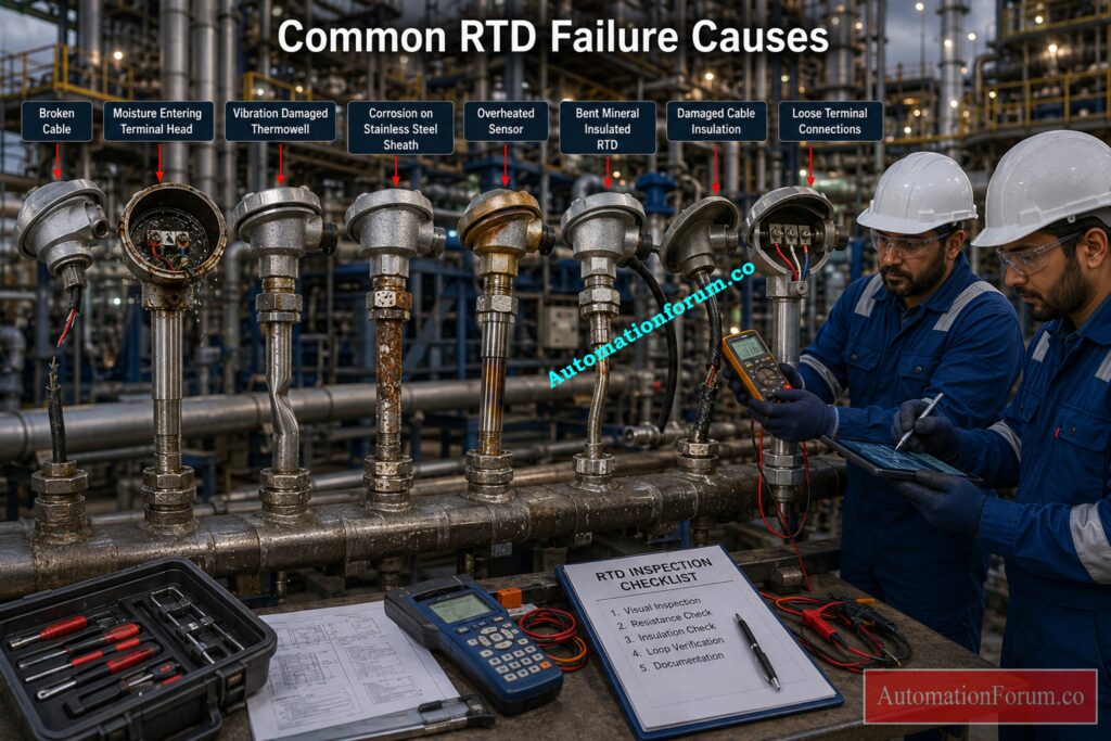
Symptoms of a Failing RTD
| Observed Symptom | Possible Cause |
| No temperature reading | Open circuit or broken lead |
| Constant low reading | Short circuit or moisture |
| Fluctuating indication | Loose connection, vibration, or cable damage |
| Slow response | Incorrect insertion depth or damaged thermowell |
| Reading differs from reference | Calibration drift or aging |
| Intermittent alarms | Moisture ingress or poor termination |
Step by Step RTD Troubleshooting Procedure
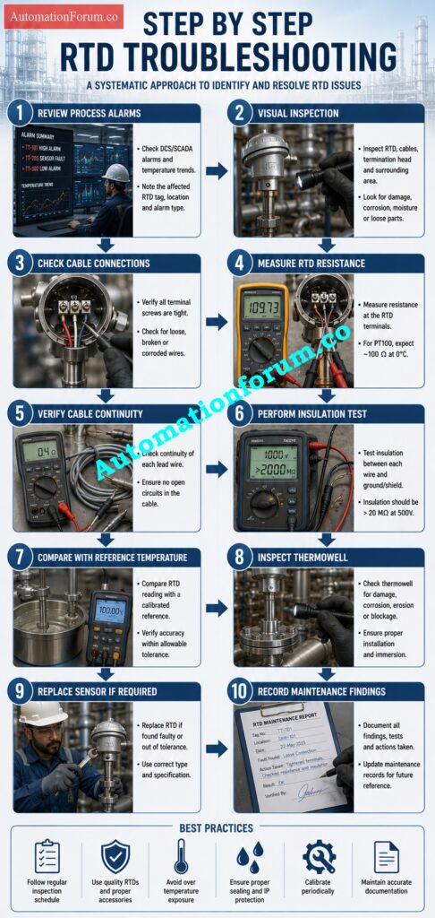
A systematic technique can pinpoint the real defect without unnecessarily changing good components..
- Check alarms and process history to see when the problem originated.
- Visually inspect the sensor, cable, junction box and thermowell.
- Look for loose terminals, corrosion, damaged cable glands and moisture
- Measure the RTD resistance using a calibrated multimeter and compare with conventional PT100 values.
- Check continuity of wiring from sensor to transmitter or control system.
- Test for insulation resistance if you suspect moisture contamination.
- Compare the RTD reading against a calibrated reference thermometer or dry block calibrator.
- Check thermowell for vibration damage, process deposits or corrosion.
- Only replace the sensor after wiring, transmitter and installation have been checked and found satisfactory.
- Document results to enable future maintenance and reliability improvement.
Prevent Costly Measurement Errors Before They Impact Plant Operations: RTD Tolerance Calculation
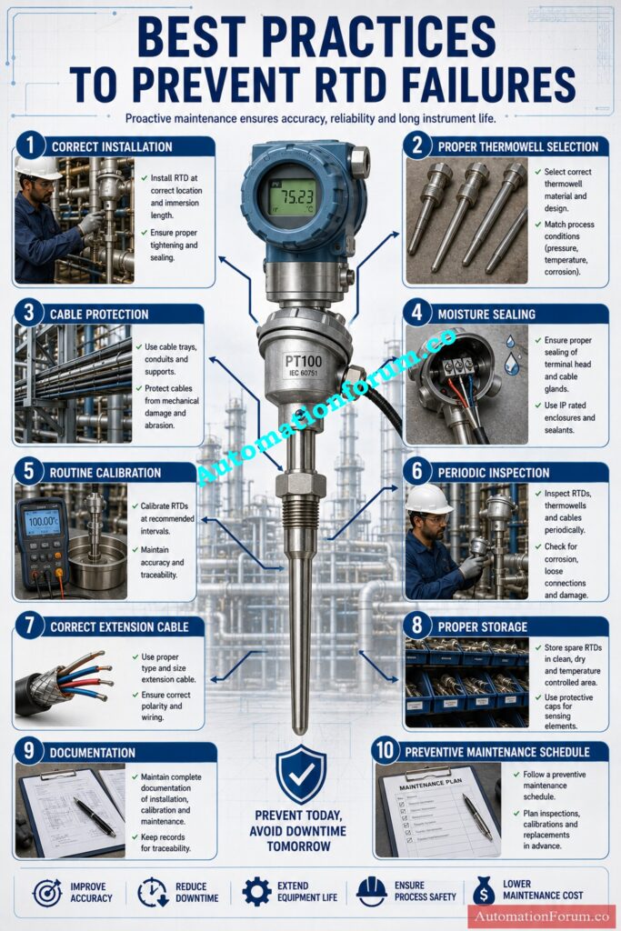
Best Practices to Prevent RTD Failures
Preventive maintenance remains the best approach to improving RTD reliability.
| Preventive Maintenance Activity | Recommended Frequency | Expected Benefit |
| Visual inspection | Monthly | Early fault detection |
| Cable and terminal inspection | Every six months | Reliable electrical connections |
| Calibration verification | Annually or as required | Maintains measurement accuracy |
| Thermowell inspection | During shutdown | Prevents vibration and corrosion failures |
| Moisture seal inspection | Quarterly | Reduces water ingress |
| Documentation review | After maintenance | Improves troubleshooting efficiency |
Additional recommendations include:
- Select the proper RTD for process temperature/pressure.
- Use correct rated thermowells.
- Route cables away from power cables.
- Seal cable glands properly.
- Sensors shall be protected during shutdown activities.
- Store spare RTD’s in a clean, dry area.
- Check three wire connections before activating the loop.
- Maintain full records of calibration and maintenance.
Make the Right Temperature Sensor Choice Every Single Time: Choosing Between Thermocouples and RTDs: A Practical Guide for Temperature Sensing
Real Industrial Example of RTD Failure Diagnosis
Root Cause Analysis
A chemical processing plant experienced erratic reactor temperature readings which resulted in unneeded control valve activity. The temperature transmitter was first suspected, but was proven to be calibrated appropriately.
Further inspection revealed that water had entered the RTD terminal head after a heavy rainfall. Ingress of moisture had been caused by a broken cable gland, resulting in reduced insulation resistance and intermittent measurement inaccuracies.
Corrective Actions Taken
The maintenance team rebuilt the cable gland, fitted a new RTD, increased weather sealing and modified the inspection checklist. Immediately the temperature of the reactor normalized, no process disruptions were reproduced and further failures were avoided.
Avoid Calibration Mistakes That Can Damage Process Reliability: 8 Steps RTD Calibration Procedure
Conclusion on Common Reasons for RTD Failures
Common Reasons for RTD: What to Know Failures allow engineers to quickly troubleshoot temperature measurement problems and avoid costly production downtime. Defective sensors are not the cause of most sensor failures, which are usually due to poor installation, vibration, dampness, wiring difficulties, aging or incorrect usage.
Best practices including routine inspection, proper installation practices, periodic calibration and systematic RTD troubleshooting greatly improve measurement reliability and extend sensor life. A disciplined preventive maintenance program not only avoids unexpected breakdowns, but also provides accurate process control, higher product quality and safer plant operation.
The Smart Wiring Upgrade Every Maintenance Engineer Should Know: Converting 2-Wire and 3-Wire RTDs into 4-Wire RTDs
Frequently Asked Questions About RTD Failures
What causes RTD failure?
RTD failure is commonly caused by vibration, moisture ingress, cable damage, loose connections, excessive temperature, corrosion, and sensor aging. RTD reliability is compromised by improper installation and/or incorrect thermowell selection.
What are the three common causes of sensor failure?
The three most common causes of sensor failure are mechanical damage, electrical connection problems, and environmental exposure such as moisture, heat, or corrosion. These kinds of problems might cause false readings or total sensor failure.
How to troubleshoot a faulty RTD?
Visually inspect the RTD and wiring for any physical damage. Measure the sensor resistance and check the cable continuity. Compare the readings to a calibrated reference . Replace the RTD if out of specification .
Calculate Sensor Performance Like an Experienced Instrumentation Professional: RTD Temperature Coefficient Calculation
What causes a thermocouple to fail?
Thermocouples can fail owing to oxidation, corrosion, vibration, high temperature, thermal cycling, insulation breakdown, or mechanical damage. Also, the thermocouple junctions can age and become contaminated , which can lead to measurement errors .
What is the most common thermocouple failure method?
The most common thermocouple failure is an open circuit resulting from a broken sensor junction or damaged lead wire. Generally, this is the result of long-term vibration, metal fatigue, or repeated thermal cycling.
How to diagnose a faulty thermocouple?
Inspect the thermocouple for obvious damage, loose connections, or corrosion and then test for continuity and output voltage using a multimeter. Check the reading against a known temperature reference or calibrated device to verify its correctness.
Why do RTDs fail?
Vibration, moisture ingress, cable damage, excessive temperature, aging, poor installation or loose electrical connections are the usual causes of RTD failure, not manufacturing defects.
How can I test an RTD?
Measure its resistance with a calibrated multimeter and check the value against the standard resistance table, for the specific RTD type, at the measured temperature.
What causes RTD drift?
Long-term exposure to high temperatures, repetitive thermal cycling and natural aging eventually modify the characteristics of the platinum element and the precision of measurements is thus decreased.
Can vibration damage an RTD?
Yes. Internal connections may fatigue or the sensing device can fracture from continuous vibration especially in the case of extended thermowells or unsupported sensors.
How often should RTDs be calibrated?
RTDs in industrial plants are usually calibrated once a year . Critical applications may require more frequent calibration depending on the operating conditions and quality requirements .
Can moisture affect RTDs?
Yes. Moisture in junction boxes, cable glands or terminal heads leads to a decrease in insulation resistance and usually results in unstable or incorrect temperature measurements.
What resistance should a healthy PT100 show?
A typical PT100 measures around 100 ohms at 0 degrees Celsius. As per the RTD standard, the resistance increases predictably with increasing temperature.
What is the difference between cable failure and sensor failure?
Signal transmission is interrupted by cable failure from damaged insulation or broken conductors, and sensor failure happens within the RTD sensing element and changes the resistance characteristics of the RTD.
When should an RTD be replaced?
Replace an RTD when it has an open circuit, severe calibration drift, physical damage, corrosion, insulation failure, or when calibration no longer meets process accuracy requirements.
Refer the below link for the Why 4 wire RTD’s measurement accuracy is better than 2 and 3 wire RTD?
