- Why Thermocouple Testing Matters in Industrial and Domestic Heating Systems
- How a Thermocouple Works Explained for Technicians
- Common Causes of Thermocouple Failure
- Equipment Required for Accurate Thermocouple Testing
- Method 1: Resistance or Continuity Test
- Method 2: Open Circuit Millivolt Test
- Method 3: Closed Circuit Load Test
- Practical Thermocouple Maintenance Tips
- Symptoms of a Failing Thermocouple
- Reasons for Low Millivolt Output
- When to Replace a Thermocouple
- Quick Field Checklist for Technicians
- Frequently Asked Questions About Thermocouple Testing
Thermocouples are among the most widely used temperature sensing elements in industrial and domestic heating systems. Their reliability, simplicity, and ability to function in harsh environments make them essential components in burners, pilot assemblies, furnaces, boilers, ovens, and several other process heating applications. Yet thermocouple failures are also one of the most common causes of pilot outages and burner shutdowns.
Why Thermocouple Testing Matters in Industrial and Domestic Heating Systems
Instrumentation technicians frequently encounter thermocouples while troubleshooting pilot flame instability, poor burner efficiency, or repeated equipment trips. In many of these cases, a multimeter can quickly determine whether the thermocouple is healthy or failing.
Safety Requirements Before Testing a Thermocouple
Work Area Safety and Isolation Procedures
Thermocouple testing is simple, but it must be performed under strictly controlled and safe conditions. Testing must always be done in a workshop or safe test area, not in a hazardous zone or where flammable gases, vapors, or energized equipment are present.
Some tests require using a lighter or small torch, and some require temporarily bypassing or removing components. This means the workbench must be clean, stable, well ventilated, and equipped with appropriate fire suppression tools.
Essential Personal Protective Equipment
All technicians must adhere to the following precautions:
- Wear your personal protective gear: safety glasses and heat-resistant gloves are a must. Before you take out a thermocouple from any device, make sure the gas supply is turned off.
- Turn off electrical circuits as needed.
- Adhere to plant work permits, lockout/tagout protocols, and safe isolation methods.
- Avoid heating or testing a thermocouple in proximity to anything that could catch fire.
Preventing Ignition Hazards During Testing
A careful and secure methodology guarantees precise measurements, while also safeguarding both the equipment and the testing environment from potential hazards like ignition or damage.
Follow This 8-Step Thermocouple Calibration Procedure Like a Pro: 8 Steps Calibration Procedure for Thermocouple
How a Thermocouple Works Explained for Technicians
Hot Junction and Reference Junction Basics
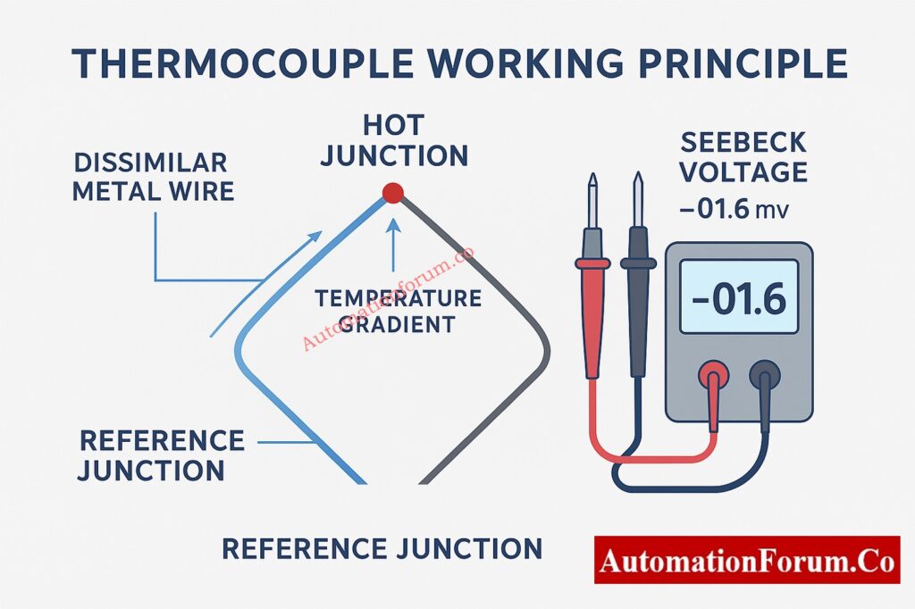
A thermocouple consists of two dissimilar metal wires joined at one end, forming the hot junction. The opposite ends are connected to an instrumentation device or control valve and act as the reference junction.
Understanding the Seebeck Effect and Millivolt Output
When the hot junction is exposed to heat, a temperature gradient develops between the two junctions, generating a small direct current voltage known as the Seebeck voltage. This output is measured in millivolts and is proportional to temperature.
In domestic and light industrial gas appliances, this millivolt signal energizes a small electromagnet inside the gas valve. As long as this voltage stays above a certain threshold, the valve remains open and the burner stays operational. If the thermocouple health deteriorates, its output drops and the valve closes, shutting down the flame.
Typical Thermocouple Millivolt Ranges in Gas Appliances
Typical operating values for standard appliance thermocouples include:
- Open circuit millivolt output of approximately 25 to 30 mV when exposed to a stable flame
- Closed circuit output of about 12 to 15 mV when connected to the valve under normal load
Understanding these values is critical because different tests detect different failure modes.
Understand the Full Procedure to Calibrate a Thermocouple Transmitter: How to calibrate Thermocouple Transmitter?
Common Causes of Thermocouple Failure
Thermocouples operate under heat, vibration, and combustion exposure. Over time, several failure mechanisms reduce output, increase resistance, or cause intermittent performance. The most typical ways that things fail include:
- The collection of soot, charcoal, or dirt at the junction reduces how well heat is transferred.
- A pilot flame that’s either too weak or not properly positioned might not fully cover the detecting tip.
- Oxidation or corrosion might happen because of high temperatures and the gasses produced during burning.
- Mechanical fatigue from continuous heating and cooling cycles.
- Internal conductor breakage caused by vibration or bending.
- Insulation deterioration or shorts between conductors and the outer sheath.
- Voltage drops under load can be caused by loose connections or damaged connectors.
Understanding these principles helps technicians choose the best diagnostic approach and interpret the data appropriately.
Learn How to Select the Right Thermocouple for Any Application: How to Select the Right Thermocouple for Temperature Measurement Applications?
Equipment Required for Accurate Thermocouple Testing
A field technician, when doing thermocouple tests, often relies on a handful of essential instruments.
- A good digital multimeter, one that can accurately measure millivolts DC and low resistance.
- Crocodile clips, or perhaps some other reliable way to connect probes.
- A tiny flame or lighter is handy for heating purposes when doing open circuit tests.
- A thermocouple test adapter for closed circuit load measurement.
- A clean workbench away from hazardous atmospheres.
- Standard hand tools for installation or removal.
- Safety goggles and gloves that can withstand heat.
After the equipment is ready and the work space is secure, you can test the thermocouple. This can be done using one or more of the diagnostic methods outlined below.
Method 1: Resistance or Continuity Test
Purpose of the Continuity Test
The continuity test checks the thermocouple’s internal connections, looking for any breaks, and also checks the resistance at the connection points. It’s particularly useful for pinpointing internal faults or subpar mechanical linkages.
Step-by-Step Procedure
- Detach the thermocouple from the appliance. If it’s difficult to remove, keep it in place, but make absolutely certain the gas supply is completely shut off.
- Examine the area visually, looking for any signs of smashed portions, kinks, corrosion, or insulation that’s been compromised.
- Switch the multimeter to continuity mode, or the lowest ohm setting.
- Attach one meter lead to the tip of the thermocouple, and the other to the connection end.
- Record the resistance measurement.
Expected Resistance Values
- A properly functioning thermocouple usually shows a resistance of only a few ohms.
- A value in the tens of ohms, or an open circuit, indicates a damaged conductor or significant corrosion.
- If the connectors are showing significant resistance, try cleaning or tightening them before retesting.
How to Interpret Continuity Test Results and Field Insights for Technicians
A continuity test alone is not enough to evaluate the condition of a connection. Even if a thermocouple has perfect electrical continuity, its millivolt output can still be affected by oxidation or contamination. An open reading, though, inevitably suggests substitution. In industrial settings, internal wire failures often happen because of too much vibration or poor installation. When installing a new thermocouple, be sure to steer clear of any parts that vibrate or move.
Compare Thermocouples vs RTDs in This Practical Temperature Guide: Choosing Between Thermocouples and RTDs: A Practical Guide for Temperature Sensing
Method 2: Open Circuit Millivolt Test
Why Open Circuit Testing Is Important
The quality of the thermocouple connection is evaluated by measuring the millivolt output when there’s no electrical load. Thermocouple health is often indicated by this.
Step-by-Step Procedure
- Switch the multimeter to the mV DC setting.
- Attach the multimeter leads directly to the thermocouple terminals. Use clips to ensure a secure connection.
- Expose the thermocouple tip to a controlled flame for a duration of roughly 20 to 30 seconds.
- Once the flame settles, have a look at the multimeter’s reading.
- Record the maximum steady millivolt output.
Expected Millivolt Output Ranges
- A healthy thermocouple should produce between 25 and 30 mV.
- A weak thermocouple may generate between 20 and 25 mV.
- Less than 20 mV indicates severe deterioration or junction oxidation.
Interpretation and Troubleshooting
A thermocouple with low open circuit output will not hold a valve open, even if continuity is good. If your readings vary or drop unexpectedly, look for loose probe contacts, unsteady heating, or unclean terminals.
Technicians commonly compare the reading to a known good thermocouple, using the same heating settings for both. This method works particularly well during maintenance shutdowns, when spare thermocouples are easily available.
Follow This Step-by-Step Thermocouple Troubleshooting Checklist: Check List: How to Troubleshoot a Thermocouple?
Method 3: Closed Circuit Load Test
Purpose of the Closed Circuit Load Test
The closed circuit test measures the thermocouple output while it is connected to the gas valve or electromagnet coil. This test replicates real operational conditions and exposes voltage drops caused by internal resistance or poor contacts.
Step-by-Step Procedure
- Install or leave the thermocouple connected to the valve.
- Use a thermocouple test adapter or meter probes to measure millivolt output across the valve terminals.
- Heat the pilot flame and allow the thermocouple to reach normal operating temperature.
- Document the millivolt reading when the valve coil is powered.
- If needed, press and hold the appliance control knob to simulate start-up conditions.
Master Thermocouple Troubleshooting with This Advanced Process-Area Quiz: Advanced Quiz on Thermocouple Troubleshooting in Process Area
Expected Millivolt Output Under Load
- Normal closed circuit output ranges from 12 to 15 mV.
- Marginal output ranges from 10 to 12 mV and may cause intermittent valve operation.
- Any value below 10 mV indicates failure under load.
Interpretation and Field Insight
This method is the most realistic because it tests the thermocouple in the exact conditions it must operate. A thermocouple might pass an open circuit test, but it could fail when the circuit is closed because of high internal resistance. In some situations, the gas valve can draw too much current in a loop controller, which therefore reduces the output. If the closed circuit output stays low, even while a working thermocouple is in place, the gas valve coil might be the culprit in a closed loop circuit.
Download the Complete Thermocouple Commissioning Checklist: Thermocouple Commissioning Checklist
Practical Thermocouple Maintenance Tips
- Always ensure the pilot flame properly envelops the thermocouple tip. A misaligned flame dramatically reduces millivolt output.
- Remove carbon deposits with gentle abrasive cleaning.
- Avoid removing material from the junction itself.
- Replace thermocouples that are old or physically damaged; repairs are not advisable.
- Avoid sharp bends when installing to prevent the internal conductor from becoming fatigued.
- Ensure electrical connections are clean and free from corrosion to maintain a consistent millivolt output.
- Document test values at each maintenance cycle to track patterns across time.
Refer the below link for Instant Thermocouple Voltage to Temperature Calculator for Engineers
Symptoms of a Failing Thermocouple
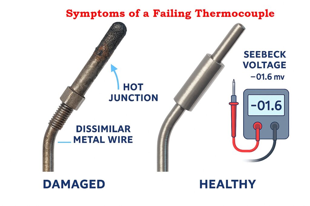
Appliances often show clear signs when a thermocouple begins to fail. Commonly reported symptoms include:
- The pilot flame goes out almost immediately when you let go of the control knob.
- The burner either won’t stay lit or extinguishes itself without warning.
- The pilot flame flickers or seems feeble.
- The thermocouple’s sensing tip shows signs of corrosion or burning.
- Discoloration and carbon buildup were observed surrounding the pilot assembly.
- Frequent, unexplained shutdowns are a persistent problem.
Ignoring these signs can lead to less effective heating and possible safety problems.
Learn How to Convert Thermocouple mV to Temperature Step by Step: How to Convert Thermocouple Millivolts to Temperature: A Step-by-Step Guide
Reasons for Low Millivolt Output
- Thermocouples produce low millivolt readings because of many mechanical and thermal factors.
- The flame can be too low, or the angle at which it touches the surface could be wrong.
- Excessive soot or combustion by-products covering the sensing tip.
- Oxidation of the hot junction. Stretched, bent, or vibrated conductors.
- Loose terminal connections might introduce extra resistance.
- High resistance can also be a result of age or prolonged use.
- If flame adjustments and cleaning do not restore performance, replacement is recommended because junction degradation is irreversible.
Explore Practical Methods to Convert Thermocouple mV to Temperature: Converting Thermocouple Millivolts to Temperature: Methods and Examples
When to Replace a Thermocouple
A thermocouple should be replaced when:
- Continuity test indicates open circuit.
- Open circuit millivolt output is below 20 mV.
- The closed circuit millivolt output is less than 12 mV.
- Severe corrosion, burnt tip, or physical damage is observed.
- Pilot outages continue to occur, despite efforts to clean and align the equipment.
- Thermocouples are inexpensive components.
- Replacing a suspect unit is often faster and more reliable than attempting continued troubleshooting.
Quick Field Checklist for Technicians
- The work area has been verified as safe and segregated.
- The visual inspection was completed.
- Maintaining continuity within reasonable boundaries.
- Open circuit output between 25 and 30 mV.
- Closed circuit output between 12 and 15 mV.
- All connectors cleaned and tightened.
- If any test fails, a replacement will be conducted.
Thermocouples are essential for the safe operation of gas appliances and industrial heating systems. The modest millivolt output directly influences how the valve works, making correct testing vital for safe and reliable functioning. With a digital multimeter and the three essential tests outlined here, technicians can accurately assess the state of any thermocouple.
Thermocouple lifespan is considerably extended by consistent testing, good installation, optimal flame orientation, and regular inspection. If test values deviate from the suggested parameters, swift replacement is key to keeping the heating system both reliable and secure.
Refer the below link to Understand Why CJC Matters for Accurate Thermocouple Measurements
Frequently Asked Questions About Thermocouple Testing
How do you test a thermocouple with a multimeter?
Switch the multimeter to read mV DC. Then, apply a little flame to the thermocouple’s tip and record the millivolt output. A healthy unit should produce approximately 25 to 30 mV open circuit. You can also check continuity or perform a closed circuit load test.
What ohms should a thermocouple read?
A thermocouple should read only a few ohms. High resistance or an open reading indicates a broken conductor or damaged connector.
How do I know if my thermocouple is bad?
Low millivolt output, open circuit resistance, unstable flame holding, frequent pilot shutdowns, or visible corrosion are common indicators of a bad thermocouple.
How to tell if a thermocouple is J or K?
Type J uses iron and constantan and usually has a black and white color code. Type K uses chromel and alumel and typically has yellow and red leads. The insulation color and cable markings are the most reliable identifiers.
How to check thermocouple type K?
Use a multimeter capable of thermocouple input or check the mV output against standard type K temperature tables. You can also identify it by its yellow and red leads according to IEC color code.
What is the lifespan of a thermocouple?
A thermocouple typically lasts one to five years in appliance use. Industrial high temperature applications may require more frequent replacement depending on thermal cycling, vibration, and environmental exposure.
Which wire is positive on a type K thermocouple?
For type K, the positive wire is chromel and usually colored yellow. The negative wire is alumel and typically colored red.
Refer the below link to Test Your Thermocouple Knowledge with This Advanced Industrial Quiz