A thermocouple must go through several crucial procedures before it can be properly installed, calibrated, and maintained.
To guarantee a thorough and secure commissioning process, this comprehensive checklist includes preparatory documents, safety considerations, pre-commissioning inspections, commissioning processes, and final documentation.
Step 1: Preparation Documents for Thermocouple Commissioning
- Instrument Loop Diagrams (ILD): Detailed loop diagrams that show the signal flow from the thermocouple sensor to the control system input, as well as all of the components, wiring details, and terminal numbers.
- Thermocouple and Transmitter Data Sheets: Manufacturer data sheets describing the type, calibration, temperature range, and accuracy characteristics of thermocouples and transmitters are available. Transmitter data sheets with input and output range characteristics.
- Instrument Wiring Diagrams: Detailed schematics displaying termination locations, wire paths, and connectors.
- Specification Sheets: Complete specifications for all relevant equipment, such as the thermocouple and related instruments, are available on specification sheets.
- Loop Folders: Arrangements of documents associated with loops, including calibration records, in well-organized folders.
- P&ID (Piping and Instrumentation Diagrams): Process flow, piping, and instrumentation details are shown in P&ID (Piping and Instrumentation Diagrams) diagrams.
- Instrument Location Layout: Drawings indicating the physical location of each thermocouple within the process area.
- Hookup Drawings: Comprehensive installation drawings that demonstrate how the thermocouple is connected to the related instruments and process.
Step 2: Safety Considerations
Make sure the following safety procedures are followed before beginning thermocouple commissioning:
- Make sure the following safety procedures are followed before beginning thermocouple commissioning:
- Obtain the required work permits and adhere to the safety protocols unique to the site. Make sure that every employee understands these protocols and follows them.
- Make use of the proper PPE, such as safety glasses and a hard hat. Make that every piece of PPE is well-fitting and in good shape.
- Create a safe work environment and employ obstacles to restrict unauthorized access. Make sure everyone on site is aware of the boundaries and that the work area is clearly marked.
- To avoid unintentional energization, make sure that electrical and process equipment is properly lockout/tagged out. Check to make sure all energy sources have been shut off and isolated in accordance with protocol.
- Make sure there is access to a safety shower and an eye wash station. To put out electrical fires, always have a fire extinguisher close by. Verify that emergency supplies are in working order and that staff members are aware of where they are and how to use them.
Step 3: Pre-Commissioning Checks for Thermocouple
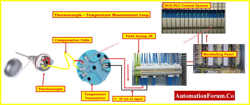
- Ensure all thermocouple is properly tagged as per the specification sheets and match the corresponding documentation.
- Make that the control system setup and specification sheet match the type of thermocouple (e.g., kind K, Type J). Verify the accuracy and calibration report of the thermocouple.
- Check to make sure the thermocouple is installed correctly in accordance with the P&ID and specification.
- For an accurate temperature reading, make sure it is fully submerged in the procedure to the designated depth.
- Make that the thermowell has adequate heat conductivity, is clear of debris, and is clean. Examine thermowell surfaces both inside and outside for damage and cleanliness. Ensure proper contact between the thermocouple and thermowell, with clean and effective thermal paste if used.
- Verify that the thermowell’s material and pressure rating are appropriate for the procedure.
- With a multimeter, verify that there is continuity between each lead after disconnecting the thermocouple leads at both ends.
- Make sure the resistance correspond to the kind of thermocouple.
- Examine the insulating resistance at the thermowell/process connection and the leads.
- Inspect the thermocouple junction (e.g., grounded, ungrounded, exposed) and its suitability for the application
- Verify that the thermocouple tips are properly grounded if specified, and check for any grounding issues that may affect signal accuracy.
- Make sure the thermocouple wiring is correctly positioned in cable trays or conduit and shielded from the elements and mechanical harm.
- Ensure the compensation cable type matches the thermocouple type (e.g., Type K thermocouple with Type K compensation cable).
- Confirm the compensation cable specifications, such as temperature range and insulation, match the application requirements.
- Verify the compensation cable is routed correctly from the thermocouple to the control system, avoiding sources of electrical noise and mechanical stress. Ensure the cable is protected from environmental factors like moisture and extreme temperatures.
- Inspect the connections at both ends of the compensation cable. Ensure proper termination techniques are used and that connections are secure and free of corrosion. Verify that polarity is maintained throughout the cable length.
- Ensure the compensation cable length does not exceed manufacturer recommendations, as excessive length can introduce measurement errors.
- Verify that the connections are clean and the wire terminations are tight. Make that the wiring shields are adequately grounded and that the labels are correctly attached to the wire on both ends.
- Make that the thermocouple is using the right model and range of transmitter. Make that the wiring and thermocouple type are configured correctly. Verify that the thermocouple input (for example, mV) and the transmitter output match (for example, 4–20 mA).
- To stop moisture intrusion, check the transmitter’s cable glands for correct tightness.
- Make that the voltage of the transmitter power supply are correct. Compare the transmitter specifications with the power supply specifications.
- To prevent ground loops, make sure the transmitter is grounded correctly in accordance with manufacturer guidelines.
Click here for How to Select the Right Thermocouple for Temperature Measurement Applications?
Step 4: Commissioning Procedure for Thermocouple
Thermocouple Output Signal Simulation
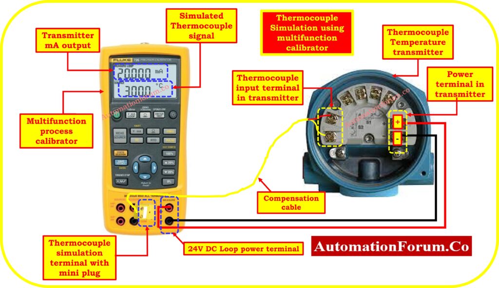
- At the field wiring termination point, inject a mV test signal that simulates the thermocouple output using a precision multifunction calibrator.
- Verify in the control room that the right instrument and point number are responding. Make sure the test signal is correctly identified by the control system.
- Verify that the temperature shown on the HMI or control system corresponds to the value of the injected mV signal. By doing this, the signal route integrity between the field device and the control system is confirmed.
Click here for How to simulate RTDs and Thermocouples using Multifunction calibrator?
Calibration Check for Thermocouple Transmitter
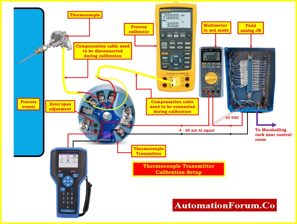
- Inject an ordered sequence of mV signal values across the thermocouple’s whole range. It is assumed that this will cover the temperature range that the process will operate normally within.
- Using a calibrated multimeter, determine the transmitter output at each injected mV signal value. These measurements should be compared to the input signal values.
- It is necessary to adjust the zero and span parameters of the transmitter in order to guarantee that the output precisely corresponds to the inputting signal. Click here for How to calibrate Thermocouple Transmitter?
- Note the observed output mA values, input mV signal levels, and any modifications made in the as-left calibration data. Save these documents for future use in troubleshooting and reference.
Click here for 8 Steps Calibration Procedure for Thermocouple
Click here for Check List: How to Troubleshoot a Thermocouple?
Verify Control System Signal Integration
- Verify that the control system’s mapping(Address) of the thermocouple input is accurate. Check that the input signal is assigned to the correct measurement point by the control system software.
- Make sure the HMI screens accurately display the temperature. Check to see if the value presented is updated in real-time and corresponds with the transmitter output.
- Verify that there is no saturation or clipping throughout the whole range of the thermocouple input signal. Verify that the signal range is free of deviations that may affect the accuracy of the measurement.
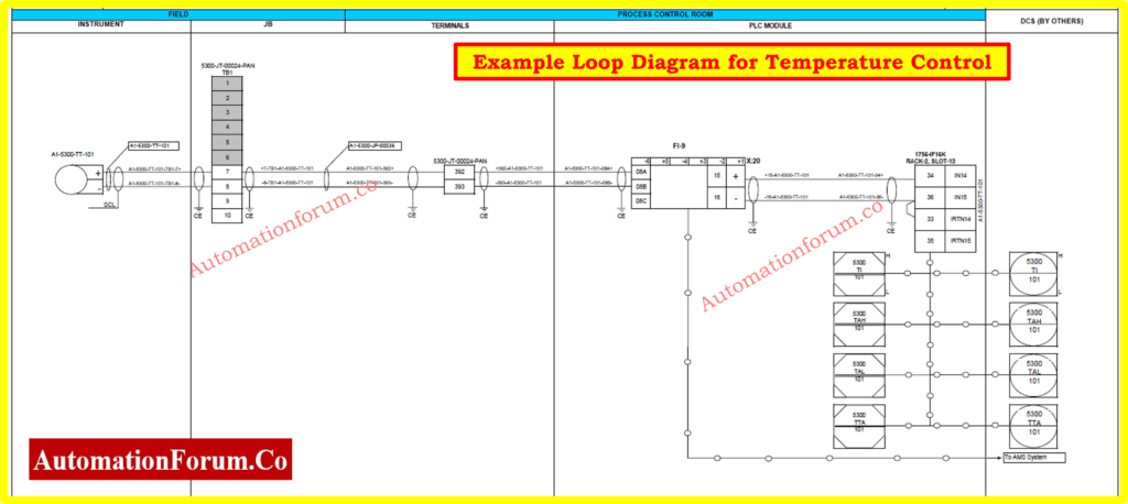
Perform Loop Check
- Use a precision multifunction calibrator to simulate a temperature change and verify the control loop’s response. Ensure the control loop adjusts the final control element (e.g., valve, damper) correctly in response to the simulated temperature change.
- For control loops, manually stroke the final control element and confirm it operates correctly. Ensure it responds as expected to the control system commands.
- Make that the logic for the alarm and shutdown trip loops activates at the appropriate setpoints by simulating the events that cause these functions to occur. Verify that shutdowns and alarms operate as expected.
Validate Process operating conditions Response
- Compare the thermocouple reading to a calibrated reference digital thermometer while the process is running normally. By doing this, it is ensured that the thermocouple measures process temperatures accurately.
- Verify that the thermocouple reading falls within the reference thermometer’s designated accuracy range. Record any variations and look into possible reasons, such installation problems or inaccurate calibration.
- Note the calibration data as-found and as-left. Keep up-to-date records for future use and to assist with continuing maintenance and calibration tasks.
Step 5: Completion of Commissioning
- The thermocouple calibration records should be updated with the data from the as-found and as-left states. Be sure to keep records that are accurate for future reference.
- Important to check that the P&ID and control system documentation are consistent with the thermocouple tag. The documentation should be checked to ensure that it is consistent and up to date.
- Obtain sign-off from the commissioning team and operations personnel, ensuring all stakeholders agree that the commissioning process is complete.
Downloadable Thermocouple Commissioning Checklist
With our detailed Thermocouple Commissioning Checklist, you can guarantee accurate temperature monitoring and dependable performance.
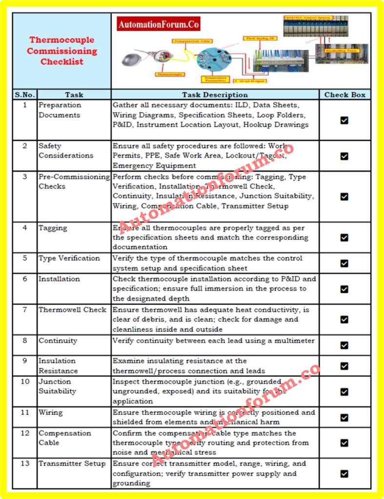
This Excel application guides engineers through critical processes, such as documentation and commissioning procedures, safety inspections, and preparation. Refer the below link to download the checklist.
Click on the link for more Essential Instrumentation Checklists


