- Simulation procedure for RTD signal by using Multifunction calibrator
- Learn how to use the multifunction calibrator
- Connect the calibrator to the RTD input
- Enable loop powered mode in calibrator
- Set the calibrator’s simulation mode
- Enter the desired temperature
- Select the most suitable simulation method
- Configure the simulation’s settings.
- Check the result
- Record and document
- How to Calibrate RTD transmitter?
- Simulation procedure for Thermocouple signal by using Multifunction calibrator
- Learn how to use the multipurpose calibrator
- Connect the calibrator to the thermocouple input
- Turn the calibrator’s simulation mode on
- Enable loop powered mode in calibrator
- Choose the type of thermocouple
- Enter your preferred temperature
- Configure the reference junction temperature
- Launch the simulation
- Check the result
- Record and document
- How to calibrate thermocouple temperature transmitter?
- The most popular sensors used to detect process temperature are thermocouples and RTDs.
- A technician can check to see if the device reacts appropriately to the temperature measured by the instrument by simulating a process sensor signal into a process instrument or control system input.
- These sensors can be simulated in a variety of ways for testing reasons.
- When simulating thermocouples or RTDs, you can use a resistance decade box and a resistance vs. temperature look-up table or a mV dc source and a mV vs. temperature look-up table.
- However, present-day temperature calibrators that perform the conversion for the user is making this method obsolete.
- Modern calibrators only require that you choose the sensor type to emulate, enter the source temperature, and connect to the devices that are being tested.
Simulation procedure for RTD signal by using Multifunction calibrator
To simulate an RTD (Resistance Temperature Detector) signal using a multifunction calibrator, follow these steps:

Learn how to use the multifunction calibrator
Learn about the features and capabilities of the device by reading the user manual. Verify that RTD simulation is supported by the calibrator.
Connect the calibrator to the RTD input
Depending on the calibrator model, you might need to connect the calibrator to the RTD input terminals using the proper cables or connections.
As illustrated in figure, attach the calibrator to the device’s input.
Connect the calibrator output using the proper configuration (2, 3 or 4-wire) to match the RTD arrangement.
Enable loop powered mode in calibrator
To connect a transmitter with a 4 to 20 mA output in loop-powered mode to a multifunction calibrator, connect the transmitter’s “+” terminal to the calibrator’s “+” terminal and the transmitter’s “-” terminal to the calibrator’s “-” terminal. Set the calibrator to loop-powered mode, and verify that the output matches the expected power supply value. Follow safety guidelines and refer to the device manuals for specific instructions.
Set the calibrator’s simulation mode
Choose the RTD signal simulation mode on the multifunction calibrator. You can produce a resistance value in this mode that relates to a particular temperature.
Enter the desired temperature
Enter the temperature value you want to simulator into the calibrator’s control interface. Make that the temperature units are correctly configured (such as Celsius or Fahrenheit).
Select the most suitable simulation method
Different simulation techniques, like fixed resistance or linear interpolation, may be available from the calibrator. You should go with the approach that corresponds to your needs the most.
Configure the simulation’s settings.
Set up any extra parameters, such as the RTD type (such as Pt100 or Pt1000) and reference temperature coefficient, that is necessary for precise simulation. For instructions on how to configure these parameters correctly, refer to the calibrator’s user handbook.
Check the result
Verify the output signal using measuring equipment. Assuming the temperature you set measure the resistance the calibrator produces and compare it to the predicted value.
You can fine-tune the output signal by changing the simulation parameters or the calibration settings on the calibrator if the simulated resistance does not precisely match the intended value.
Record and document
After successfully simulating the RTD signal, note the simulation’s variables and any calibration settings that were applied. For future use as a reference or for the calibration certificate, note the simulated resistance values and the corresponding temperatures.
Always follow the exact instructions that came with your multifunction calibrator, since they may differ depending on the model and firmware of the device.
How to Calibrate RTD transmitter?
Check out the link below for further information on how to carry out the calibration of RTD temperature transmitter.
How to Calibrate RTD transmitter?
Simulation procedure for Thermocouple signal by using Multifunction calibrator
To simulate a thermocouple signal using a multifunction calibrator, follow these steps:
Learn how to use the multipurpose calibrator
Learn about the features and capabilities of the devices by reading the user manual. Verify that thermocouple simulation is supported by the calibrator.
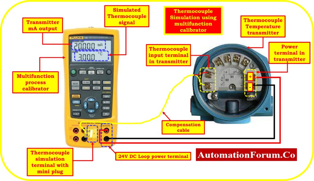
Connect the calibrator to the thermocouple input
Depending on the particular calibrator model, you might need to connect the calibrator to the thermocouple input terminals using the proper compensating cables or connections. Remove the process measurement sensor connector and replace it with the test connection wires as shown in the image.
Connect the compensation test wires’ mini-connector to the calibrator’s TC source connection.
Turn the calibrator’s simulation mode on
Choose the thermocouple signal simulation mode on the multifunction calibrator. In this mode, you can produce a microvolt or millivolt value that relates to a particular temperature.
Enable loop powered mode in calibrator
To connect a transmitter with a 4 to 20 mA output in loop-powered mode to a multifunction calibrator, connect the transmitter’s “+” terminal to the calibrator’s “+” terminal and the transmitter’s “-” terminal to the calibrator’s “-” terminal. Set the calibrator to loop-powered mode, and verify that the output matches the expected power supply value. Follow safety guidelines and refer to the device manuals for specific instructions.
Choose the type of thermocouple
Select the type of thermocouple that is appropriate with the one you wish to simulate (for example: Type K, Type E, Type J, or Type T). By doing this, it is ensured that the calibrator produces the appropriate voltage output for that type of thermocouple.
Enter your preferred temperature
Enter the temperature value you want to emulate into the calibrator’s control interface. Make that the temperature units are correctly configured (such as Celsius or Fahrenheit).
Configure the reference junction temperature
A reference junction temperature for thermocouples is necessary for precise simulation. The ambient temperature at the thermocouple input terminals which is normally the reference junction temperature, should be entered.
Launch the simulation
To start producing the simulated thermocouple signal, turn on the calibrator’s simulation mode. According to the temperature value you provided, the calibrator will produce a microvolt or millivolt.
Check the result
Verify the output signal using a measuring device. Compare the microvolt or millivolt produced by the calibrator to the anticipated value based on the temperature you specified.
You can fine-tune the output signal by changing the calibration settings on the calibrator or the simulation parameters if the simulated microvolt or millivolt value does not exactly match the predicted value.
Record and document
Following a successful simulation of the thermocouple signal, note the simulation’s settings and any calibration parameters that were applied. For future reference or certification of calibration, note the simulated microvolt or millivolt values and the corresponding temperatures.
Always follow the exact instructions that came with your multifunction calibrator, since they may differ depending on the model and firmware of the device.
How to calibrate thermocouple temperature transmitter?
Check out the link below for further information on how to carry out the calibration of thermocouple temperature transmitter.
How to calibrate Thermocouple Transmitter?