Table of Contents
- What is a temperature transmitter?
- How do you calibrate a temperature transmitter?
- Purpose and Scope:
- What instrument is usually used to calibrate a temperature transmitter?
- Tools required for Temperature Transmitter Calibration:
- Safety
- Calibration Setup
- Calibration procedure
- Example calibration
- Recording calibration
- Completion of calibration
- Sample calibration report
What is a temperature transmitter?
- A temperature transmitter is an instrument that transforms the signal from a temperature sensor into a standardized instrumentation signal that represents the temperature of a process variable that is being monitored and controlled.
- The 4 to 20 mA output signal is the most typical range for transmitter instrumentation.
- A controller receives the signal from the temperature transmitter, decides what action is necessary, and then produces the necessary output signal. Process control today uses either a PLC or a DCS as a controller.
- When the temperature changes, the thermocouple changes its voltage. Only two wires are used in thermocouples.
- When a process’s lowest temperature is being measured, a thermocouple input transmitter will draw 4 mA of current.
- As the process temperature increases, the transmitter will draw proportionally more current until it reaches 20 mA. The maximum temperature sensed by the thermocouple is represented by this 20 mA signal.
- The temperature range that the output current signal will represent is determined by the internal signal-conditioning circuitry of the transmitter (driven by a portion of the 4-20 mA current).
How do you calibrate a temperature transmitter?
Purpose and Scope:
The detailed description of this procedure demonstrates how to calibrate thermocouple temperature transmitters in the process area utilizing standards.
What instrument is usually used to calibrate a temperature transmitter?
Tools required for Temperature Transmitter Calibration:
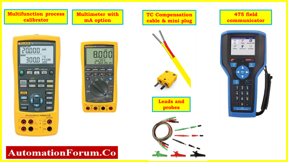
- Necessary hand tools.
- Multifunction process calibrator.
- Standard Multimeter.
- Test leads and probes.
- TC Compensation cable and mini TC plug.
- Soft Cloth for cleaning.
- Communicating instruments are necessary, such as a 475 Hart communicator if it is a smart transmitter.
Safety
- Please follow this link for more information on process industry fundamental safety, recommendations in general, and calibration of operations.
Process Industry Calibration Process: Basic Safety and General Aspects
- Request that the panel operator configure the controller in manual mode for the ESD loop and MOS (Maintenance Override Switch) for the thermocouple temperature transmitter control loop.
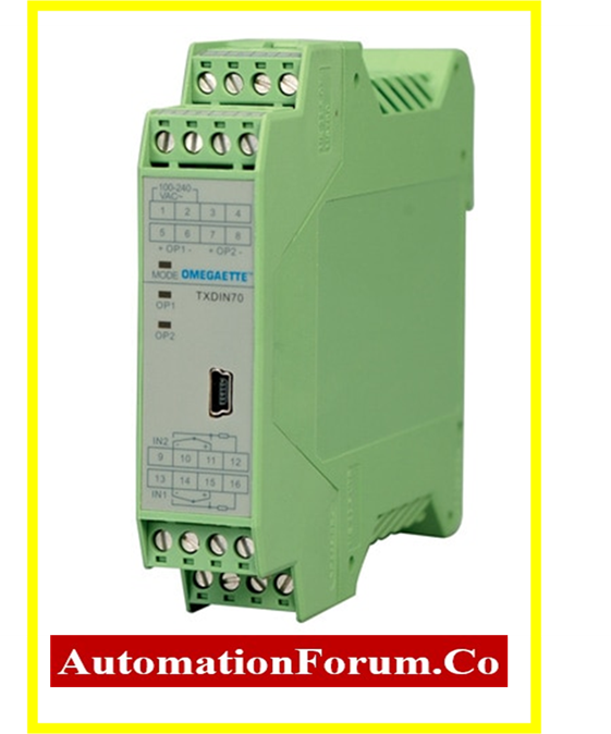
- Locate the thermocouple temperature transmitter you want to calibrate.
- Verify the thermocouple temperature transmitter is the appropriate one, and note any important details, like the Tag number (e.g. the manufacturer, model number, temperature range, type of sensor input etc.).
- Keep in mind that this fundamental procedure could need to be modified depending on the specific thermocouple temperature transmitter and process location. Always follow any manufacturer’s guidelines as well as regional safety standards when working with a thermocouple temperature transmitter along with any other part of process equipment.
- Follow all relevant lockout/tagout procedures to prevent an unintentional start. Make sure the thermocouple temperature transmitter is kept apart from the operation.
Calibration Setup

- The location of the thermocouple temperature transmitter and calibration equipment must be free from electromagnetic interference and vibrations. In addition, the area must be well-ventilated and illuminated.
- Obtain all of the test equipment and materials needed for the thermocouple temperature transmitter calibration.
- Depending on the transmitter’s particular model and maker, a compensation cable may need to be disconnected from a thermocouple temperature transmitter. Even though, the following general procedures could assist you in disconnecting the compensation cable:
- The thermocouple temperature transmitter should have its power turned off, and any wires or connectors should be unplugged from the local junction box or Marshalling panel by referring to the instrument loop diagram.
- Identify the cable used for compensation at the temperature transmitter. This cable may be linked to a different terminal block or connector on the transmitter; it is normally color-coded.
- Determine the kind of connection that is utilized to join the transmitter’s compensating cable to the transmitter. Screw terminals, spring-loaded terminals, and push-in terminals are a few examples of typical connector types.
- Release the connector or terminal holding the compensating cable in place by using the proper tool, such as a screwdriver or pliers. Throughout this process, take care not to harm the connector or the cable.
- Remove the compensating cable out of the transmitter gently after releasing the connector or termination. To avoid damage, make sure to keep the wire straight and avoid bending or twisting it.
- Label the compensating cable if necessary to indicate its position and connection locations for future use.
- Determine the type of thermocouple and compensating cable used in the transmitter, then obtain a limited amount of that same type of cable and mini TC connector.
- As shown in the picture, one end of the compensation cable connects to the TC input terminal of the transmitter and the other end to the thermocouple signal simulation terminal of the process calibrator with a mini plug .
- Between the junction box and the thermocouple temperature transmitter, use probes and a lead to create a series-connected analogue input loop to the multimeter (mA mode).
- If the thermocouple temperature transmitter is smart, connect the HART communicator to its terminal and establish communication.
- The connections have been established and are currently being prepared for the calibration of the thermocouple temperature transmitter, as shown in the diagram.
Calibration procedure
- Examine the thermocouple temperature transmitter’s compensation cable simulation input connections and power wire connections for stability.
- Turn on the thermocouple temperature transmitter’s power supply and check for power supply presence in the transmitter’s terminal.
- A number of thermocouple temperature transmitter parameters can be confirmed by checking the instrument data sheet. Typical parameters are the tag number, kind, LRV, and URV.
- A HART communicator can be used to check the parameters of a thermocouple temperature transmitter.
- Turn on the process calibrator and select the TC source mode and thermocouple input type.
- Configure the simulation input range in the process calibrator with the transmitter’s LRV and URV.
- As the Cold Junction Compensation, select Internal, External, or Fixed.
- Decide whether to use Fixed, External, or Internal as the Cold Junction Compensation.
- If an ice bath is utilized, the fixed option must be selected and the temperature set to 0°C. If the External option in the CJC is chosen, a PRT (platinum resistance thermometer) must be attached to the process calibrator and used to monitor the temperature of the ice bath or heat source (atmospheric temperature) in which the Thermocouple Reference Junction is positioned.
- Normally the internal CJC is used nowadays.
- Additionally, check the cold junction compensation (CJC) mode in the calibrator and enable CJC in the calibrator if it is enabled in the transmitter with an automatic internal sensor.
- When choosing the internal compensation in both the transmitter and the calibrator, place the multi-function process calibrator as close to the transmitter as possible to eliminate the CJC compensation error.
- The HART communicator or the instrument data sheet might be used to refer to this compensation data.
- The thermocouple is replaced in this calibration by a multifunction process calibrator that produces a temperature range in millivolts with CJC compensation.
- The Zero and Span settings on older thermocouple temperature transmitters are multi-turn potentiometer adjustments.
- When the simulated temperature is 0%, the Zero pot is adjusted to create 4 mA, and when the simulated temperature is 100%, the Span pot is adjusted to create 20 mA in the transmitter output.
Example calibration
- Let’s use calibrating a temperature transmitter attached to a thermocouple as an example, assuming a temperature range of 50 to 950 degrees Celsius.
- Now, set the calibrator to inject a temperature signal at 50°C (LRV), and check the multimeter; it should read 4 mA.
- If the 4mA reading is not shown on the multimeter display, use the Zero adjustment to adjust the thermocouple temperature transmitter output to 4mA as necessary.
- Now, configure the calibrator to inject a temperature signal at 50 °C (LRV), and then check the multimeter; it should display 4 mA.
- Use the Zero adjustment to adjust the thermocouple temperature transmitter output needed if the 4mA reading is not shown on the multimeter display.
- Set the calibrator to inject a temperature signal at 950 °C (URV) for Span calibration, and then check the multimeter; it should show 20 mA.
- If the 20mA reading is not displayed on the multimeter display, adjust the thermocouple temperature transmitter output using the span adjustment.
- If the thermocouple temperature transmitter is a SMART type, you can adjust the zero/Span current value by using the HART communicator.
- To calibrate the thermocouple temperature transmitter to the required tolerance, repeat the calibration procedure as many times as necessary.
- The calibration procedure may vary based on the particular process calibrator and thermocouple temperature transmitter being utilized. Thus, before starting off, make sure you adhere to the process calibrator manufacturer’s directions.
Recording calibration
- Check the linearity of the temperature transmitter output at 0%, 25%, 50%, 75%, and 100% in both the upscale and downscale directions to ensure that the thermocouple temperature transmitter is producing the correct output values.
- Then calculate the required output reading(mA) into required units(temperature) by using this formula.
For Desired current output signal (mA):
I mA=[(maxi. mA-min. mA )/(URV temp.-LRV temp.)]*(PV measured temp.-LRVtemp)+min. mA
For Desired temperature process value :
PV temp.=[((URV temp.-LRV temp.)/(maxi. mA-min. mA)]*(I measured mA-min. mA))+LRV temp.
- Calibration of temperature transmitter is necessary if the output value does not fall within an acceptable range. If the output values have once again deviated from the permitted range, the thermocouple temperature transmitter needs to be serviced or replaced.
- The temperature transmitter doesn’t need to be calibrated further if all output values (+/- %) fall within accepted limits.
- The blank calibration report’s as found/as left column should be filled in with the output data reading of thermocouple temperature transmitter.
Completion of calibration
- Attach the calibration label to the thermocouple temperature transmitter once the calibration has been successfully performed.
- Attach the calibration label to the thermocouple temperature transmitter once the calibration has been successfully performed.
- Clean the test equipment and communicator when the calibration is over, store them safely, and make a note of the thermocouple temperature transmitter calibration data for later use.
- Remove the thermocouple temperature transmitter connections, multifunction process calibrators, and other calibration tools.
- The connections for the thermocouple temperature transmitter must be put in the processing area.
- Verify the cleanliness of the workplace.
- De-isolate the equipment.
- Restore the thermocouple temperature transmitter signal’s bypassed or suppressed level.
- Before using the thermocouple temperature transmitter, make sure it is working properly.
Sample calibration report
The following figure illustrates how a multimeter and process calibrator were used as a reference to calibrate a thermocouple temperature transmitter sample report in a process area.
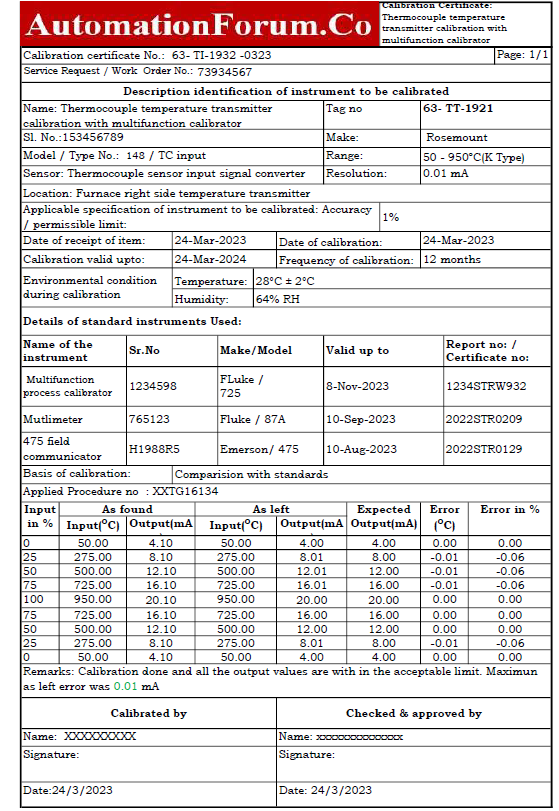
By selecting the link below, you can get the Excel document that was used to create the thermocouple temperature transmitter calibration report.