Contents
- HART Overview
- HART Technology
- How does the HART protocol work?
- What is a Bell 202 telephone communication standard?
- HART Networks
- Communication Modes
- Device Description
- What are the Benefits of the HART Protocol in Industrial Automation?
- Benefits of HART Protocol
- HART technology helps us to:
- Features of HART technology
- Specifications of HART Protocol
- Advanced HART Application
- Disadvantages of HART protocol
- During, the landline telephone era, we may notice the Caller ID display function to get caller information to know “who is calling”.
- In an industrial automation network, a microprocessor-based smart field device does the job of “who”.
- In addition to this, HART Communication allows a host system sends data to the smart instrument
HART Overview
- Highway Addressable Remote Transducer is abbreviated as HART.
- HART came out during the late 1980s
- HART is based on Caller ID technology for analog telephone system
- HART protocol is considered a standard method to exchange digital information across smart or intelligent field instruments and control host systems such as DCS, PLC, or Handheld Communicator through analog cables.
- HART is a bi-directional communication protocol.
- In today’s technology, most of the intelligent or smart field devices installed in various process industries are smart-enabled.
- A host may be any software application from a technician’s hand-held device or desktop to a plant’s process control system, asset management, safety, or other system using any control platform.
HART Technology
- HART technology is easy to use for continuous online diagnostics.
- Very reliable for calibration and commissioning of smart instruments.
- Communication host with smart devices has several reasons. These include,
- Device Configuration or re-configuration
- Device Diagnostics
- Device Troubleshooting
- Reads additional process variables generated by the field device.
- Device Health
- Device Status and much more.
It has undergone continuous development, up to and including automation products now shipping with built-in Wireless HART Communication.
How does the HART protocol work?
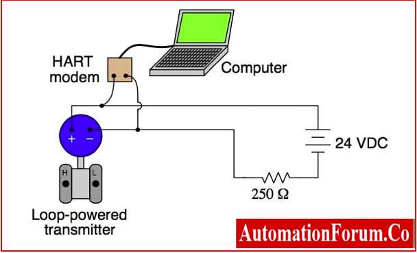
- The HART Protocol employs Frequency Shift Keying (FSK) method to overlap digital communication signals at a low level on top of the 4-20mA.
- HART communicator imparts two simultaneous communication channels one analog signal of 4-20mA and the other one digital.
- An analog current signal of 4 20mA transmits the primary process variable in the case of a field instrument using the 4-20mA current loop through the cable that supplies power to the instrument.
- The host system then transforms the current signal to a physical quantity according to parameters defined by HART Software. For example, 4 mA = 40 degrees Celsius.
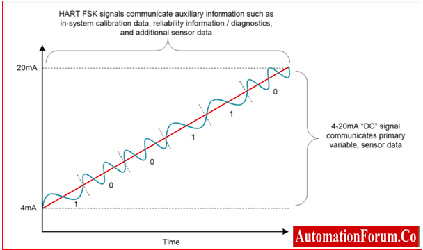
- Additional device information is interfaced through a digital signal superimposed on the analog signal.
- The digital signal consists of information from the field device such as device status, diagnostics, additional measured or calculated values, etc.
HART Communication protocol
- The HART communication protocol works on the Bell 202 telephone communication standard using the principle of frequency shift keying (FSK).
- The digital signal represents bits 1 and 0 and comprises two frequency values of 1,200Hz and 2,200Hz, respectively.
- Sine waves of these two frequencies are superimposed on DC analog signal cables for simultaneous analog and digital communications.
- Since, the average value of the FSK signal is always zero, the 4 to 20 mA analog signal is not affected.
- The response time of a digital communication signal is up to 2 to 3 data updates per second without interrupting the analog signal
- For communication, the minimum loop impedance required is 230 ohms.
- The HART Protocol enables 2-way field communications to/from a smart field instrument.
- The HART Protocol communicates at a speed of 1200 bps without disturbing a 4 to 20mA signal.
- HART Protocol allows a master to get more digital updates every second from the smart field device.
- since the digital FSK signal is phase continuous, there is no conflict with the 4-20mA analog signal.
- HART technology is a master/slave protocol, where the slave called a smart field device allowed to speak only when spoken to by a master.
- The HART Protocol can also be used in different modes such as point-to-point to communicate information to & from smart field instruments and central control or monitoring systems.
- HART Communication exists only between 2 or more HART-enabled devices they may be smart field devices and control systems or monitoring systems. Communication occurs using standard instrumentation grade wire and using traditional wiring and termination practices.
What is a Bell 202 telephone communication standard?
- The Bell 202 telephone communication standard was developed in early 1976 by the Bell System.
- It specifies Audio Frequency-Shift Keying (A-FSK) for encoding & data transfer at a rate of 1200 bits per second, with half-duplex mode.
- This system has individual circuit sets for 1200 bps and 300 bps.
Frequency Shift Keying
- Frequency-shift keying (FSK) is a method of transmitting digital signals through discrete signals.
- Logic 0 (low) and Logic 1 (high) are the two binary states in a binary frequency-shift key mechanism represented by an analog waveform.
- What is a deviation or shift point?
- Deviation or shift point is the distance between logic 0 and logic 1.
- Logic 0 state is described by a wave at a specific frequency, and Logic 1 state is described by a wave opposite to Logic 0.
- A modem converts the binary data received from a computer to FSK format to transmit over telephone lines, cables, optical fiber, or wireless media.
- The modem also converts incoming FSK signals to digital low and high states for a computer to understand from a binary standpoint.
HART Networks
The HART Protocol allows digital communication with field devices in two network configuration
Point-to-Point Configuration

- In point-to-point configuration, the traditional analog signal of 4 to 20 mA is used to communicate one process variable, but configuration parameters are transferred digitally HART protocol.
- Here, the HART signal doesn’t affect the 4 to 20 mA analog signal.
- The HART communication signal provides access to secondary variables used for operations, commissioning, maintenance, and diagnostic purposes.
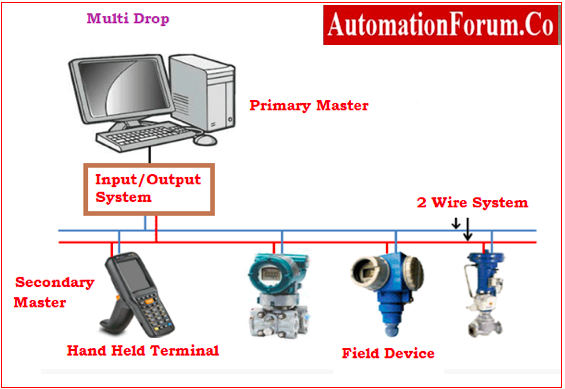
Multi-drop Configuration
- This mode consists of an optional “burst” communication for a single device to transmit a standard HART signal.
- In this mode, all process variables are digitally transmitted.
- Burst communication mode provides higher update rates which are normally restricted to point-to-point configuration.
- This multi-drop mode needs only a single pair of wires, if applicable, safety barriers, & auxiliary power supply for more than 10 field devices.
- The field device polling addresses in multi-drop mode are greater than zero.
- The current signal through each instrument is limited to a minimum value of 4 mA.
Communication Modes
Master Slave Mode
- HART is a master-slave communication protocol.
- Each field device or slave communication is initialized by the master device.
- Two master devices can connect to each other to make a HART loop.
- Generally, a primary master may be Distributed Control System (DCS), Programmable Logic Controller (PLC), or a Personal Computer (PC).
- But, the secondary master may be a handheld terminal or another PC.
- Slave device includes field instruments such as transmitters, actuators, and controllers that respond to commands issued from the primary or secondary master.
Burst Mode
- There are some HART communicators that support the optional burst communication mode.
- Burst mode enables faster communication for 3 to 4 data updates per second.
- In burst mode, the master commands the slave device to transmit a standard HART message such as a process variable.
- This message is being received by the master at a higher rate until it instructs the slave to terminate bursting.
Device Description
- Some HART configurators use Device Descriptions (DD) to receive details about process variables and HART field device functions.
- This Device Description (DD) contains information required by the host application for communication with the field device.
- HART Device Description Language (DDL) is used to write the Device Description.
- A Device Description provides a detailed representation of every parameter and function in a standard language.
- Device Description merges all of the information required by the host application into a single structured file.
- The Device Description point outs supported common practice commands as well as the format and structure of all device-specific commands.
- A Device Description for a HART field device is identical to a computer printer driver.
- Device Description eradicates host suppliers to develop and support custom interfaces and drivers.
- Device Description source files for HART devices bear like a file written in the C programming language.
- Device Description files are submitted to HCF DD Library for HCF registration.
- To ensure specification conformity each DD submitted to Quality checks.
- The HCF DD Library is the origin for managing and distributing all HART DDs to expedite their use in host applications such as PCs and handheld terminals.
What are the Benefits of the HART Protocol in Industrial Automation?
Benefits of HART Protocol
- Helps for better use of device data to optimize its functional capacity.
- Reduces the stoppages due to equipment failure by identifying the potential problems before they exist.
- Minimizes device maintenance and inventory costs.
- Reduce the time between the identification and resolution of the occurred problem.
- Improves Safety Integrity Levels through advanced diagnostics.
- Automate record keeping for compliance purposes.
- When utilized for the commissioning, calibration, and continuous online diagnostics of smart devices, HART technology is simple to use and very dependable
- Device Configuration or re-configuration
- Device Diagnostics are fairly simple.
- Device troubleshooting is simple.
- Reading the additional measurement results the device provides.
- Device Status and Health
HART technology helps us to:
- Advantages the capability of a whole set of intelligent device data for operational improvements.
- Increase asset productivity
- Validates the integrity of loops
Increase Plant Availability
- Detect real-time device connection problems.
- Minimize the bang of variance by gaining warnings.
- Integrating the system for detecting previous undetectable problems.
- Avoids unscheduled shutdowns.
- Gain early warnings of variances in device, product, or process performance.
- Speeds up the troubleshooting between the identification and resolution of problems.
Reduce Maintenance Costs
- Quick verification and validation of control loop and device configuration.
- Reduce unnecessary field checks through remote diagnostics.
- Verifying trend data for predictive maintenance diagnostics.
- Reduce spare device management costs.
Improve regulatory compliance
- Enables automated record
- Provides automated safety testing and shutdown.
- Raise safety integrity level with advanced diagnostics.
Features of HART technology
- The standard HART technology range from simple compatibility to a broad product
- Similarity with standard 4 to 20mA wiring.
- Transmitting digital data simultaneously.
- Simplicity through direct menu-driven interfaces
- Reduces risk through a highly accurate protocol
- Simplicity and efficiency of application.
- Extensive range of products.
- A platform for the independent interoperability of devices.
Specifications of HART Protocol
- The current version of the HART Protocol is 7.3. The “7” represents the major level and the “3” represents the minor level.
- The HART Protocol implements 1, 2, 3, 4, and 7 layers of the OSI model
1.Physical Layer
- It is based on the Bell 202 standard, using FSK to communicate at 1200 bps.
- The signal frequency represents bit values of 0 and 1 are 2200 and 1200Hz respectively.
- This signal is superimposed at a low level on the 4-to-20mA analog measurement signal.
2.Data Link Layer
- This Layer defines a master-slave protocol
- Here a field device is replied to only when it is spoken to.
- This layer consists of two master devices control system as a primary master and a handheld HART communicator as a secondary master.
- Up to 15 slave devices can be connected to a single multidrop cable pair.
- The timing rule defines when each master may initiate a communication transaction.
3.Network Layer
- This layer enables routing, end-to-end security, and transport services.
- It governs “sessions” for end-to-end communication for corresponding devices.
4.Transport Layer
- This layer ensures the successful propagation of a signal from one device to another.
- This layer ensures end-to-end successful communication.
5. Application Layer
- This layer defines the Protocol supported commands, responses, data types, and status.
- Here, the public commands of the protocol are classified into four groups
- Universal Commands: provides functions to be implemented in all field devices
- Common Practice Commands: provides functions common to many field devices.
- Device Specific Commands: provides unique functions to a particular field device
- Device Family Commands: provides a set of standardized functions with particular measurement types
Advanced HART Application
- HART protocol is evident since it uses the inherent feature of the HART protocol at 4-20 mA for both analog and digital communication signals transmitted over the same wiring simultaneously.
- The HART-compatible transmitter has an internal PID controller.
- The device is configured for a 4 to 20 mA loop current proportional to the control PID output.
- It is used to drive the position of the valve.
- The control loop executes between the transmitter and the control valve.
Disadvantages of HART protocol
- The slowness of the digital transmission in HART is a drawback.
- A HART multi-drop loop may link up to 16 HART devices at once. If this is the case, then the value of the analogue signal will always be 4mA.
- At any one moment, it is only able to monitor a single process variable.
- Compared to other Fieldbus systems like Profibus and Foundation Fieldbus, this type of protocol is a bit slower. So this slow response time causes some problems in some industrial applications.
- In most cases, the speed of the HART protocol is adequate for use in simple monitoring systems, provided that the process variables do not change at a fast rate.
 is a two-way communication protocol that enables data access between host systems and smart field equipment.)