- 4-20 mA Current Loop: Why It’s Standard
- Why not start at 0 mA?
- What is Live Zero?
- Live Zero Illustration
- What is Dead Zero?
- Dead Zero Illustration
- Key Differences Between Live Zero and Dead Zero
- Why is Live Zero Preferred?
- Examples of Live Zero Ranges
- Real-World Scenario: What Happens in a Fire Incident?
- FAQ on LIVE ZERO and DEAD ZERO
- What is the difference between Live Zero and Dead Zero?
- What is the difference between 4-20 mA and 0-20 mA signal systems?
- What does “Live Zero” and “Dead Zero” mean in sensors?
- What other signal ranges use Live Zero principles?
- What is the purpose of Live Zero?
- What does “Zero Live” mean in two-wire systems?
- Why is 4-20 mA the industry standard?
- Why choose a Live Zero system like 4-20 mA?
Analog signal transmission is essential in the field of industrial automation and instrumentation in transmitting process variable readings from field devices to control systems such as PLCs and DCS. In process technologies, the 4-20 mA current loop is the most often used standard for analog communication.
Particularly in relation to signal interpretation, fault detection, and system reliability, a regular topic in interviews and field troubleshooting is the distinction between Live Zero and Dead Zero. For engineers using analog loops, the two diagrams offered precisely show this difference which is both useful and necessary.
4-20 mA Current Loop: Why It’s Standard
Worldwide use of the 4-20 mA current loop stems from its robustness and capacity to differentiate between normal signal values and defective circumstances. The loop generates a current between 4 mA that is, 0% of the process variable and 20 mA that is 100%.
Why not start at 0 mA?
A signal failure such a broken cable or disconnected sensor might be indistinguishable from an actual 0% measurement if 0 mA were used to indicate 0% of a process variable (such as pressure, temperature, flow, etc.). That’s when the ideas of Live Zero and Dead Zero start to matter are present.
Instrumentation Logic Behind: Why not use 0-20mA & 0-15psi instead of 4-20mA & 3-15psi?
What is Live Zero?
Usually in a 4-20 mA signal range, Live Zero is the minimum valid current signal. Usually 4 mA. Though it makes 0% of the measured process variable, in the current loop it is still a live and healthy signal.
Within the structure (As shown picture below) of a pressure transmitter calibrated from 0 to 6 bar:
- 4 mA = 0 bar (Live Zero)
- 12 mA = 3 bar
- 20 mA = 6 bar
Easily Determine Output Ranges with: Transmitter Calibration Span, LRV and URV Value Calculator from Measured 4 to 20 mA
Live Zero Illustration
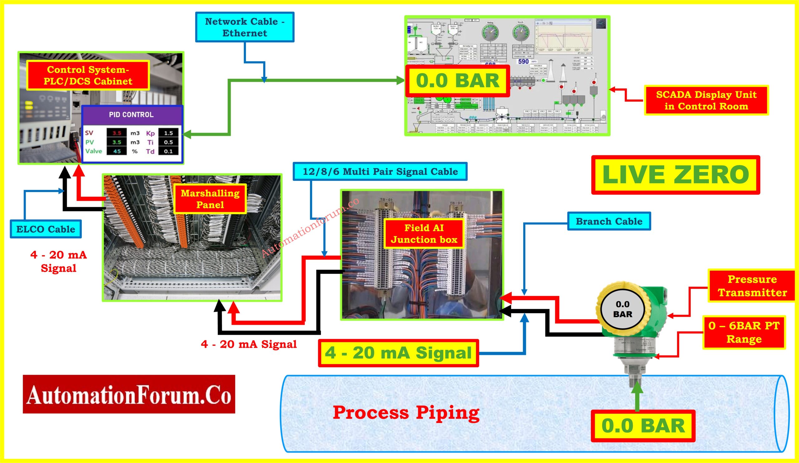
The pressure transmitter in the above shown live zero image is measuring 0 bar and mounted on process pipes. Still, it is actively producing a 4 mA current that finds the Field AI Junction Box, the Marshalling Panel, and ultimately the PLC/DCS system. The clearly reflecting process state shown on the control room SCADA display is 0.0 BAR.
All components in the signal chain are connected properly:
- Field transmitter is energized.
- Signal cable is intact.
- 4 mA is flowing, indicating 0 bar pressure but a working loop.
Live Zero has been perfectly demonstrated here. 0 process value accompanied by a valid current signal.
Step-by-Step Tutorial on: How to simulate 4-20ma signal with Loop Calibrator ?
What is Dead Zero?
Dead Zero is the state when the current in the loop is exactly 0 mA, therefore indicating a signal failure or open loop condition. It is a signal of something gone wrong in the loop rather than a real process measuring tool.
In practical scenarios, a current of 0 mA can mean:
- Cable damage
- Transmitter is powered off
- Disconnected wiring
- Blown fuse
- Bad terminal connection
Dead Zero Illustration
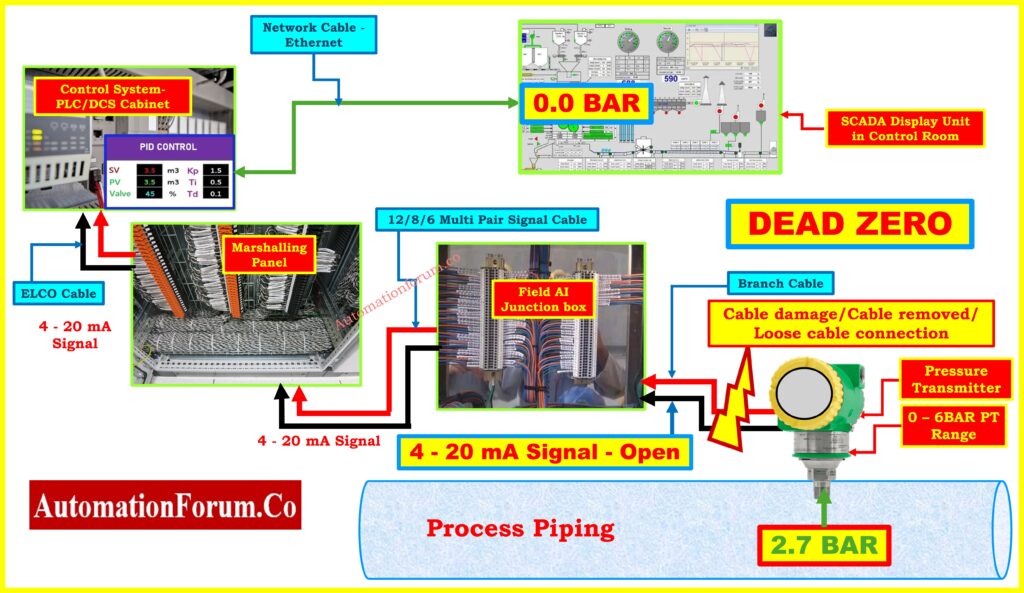
The process pressure in the above displayed dead zero figure is 2.7 BAR, which should equate to roughly 10 mA of current in the loop. But the signal wire is disconnected for a problem maybe a loose cable, rust, or physical damage.
The loop thus becomes open.
- The loop becomes open.
- The current drops to 0 mA.
- The controller receives no signal.
- The SCADA display presents misleading 0.0 BAR, which does not represent the true process value.
The SCADA display presents misleading 0.0 BAR, which does not represent the true process value.
Refer the below link for How to Safely Check the mA Current of an Instrument Loop Using a Multimeter
Key Differences Between Live Zero and Dead Zero
| Aspect | Live Zero | Dead Zero |
| Current Value | 4 mA | 0 mA |
| Meaning | Valid signal representing 0% value | No signal – loop failure |
| Process Condition | Actual zero reading (e.g. 0 bar) | Unknown – system can’t detect real value |
| Detectability | Normal operating condition | Fault indication |
| Troubleshooting | No action required | Check power, wiring, transmitter |
| Example (4-20 mA) | 4 mA = 0 bar | 0 mA = Fault despite real value being 2.7 bar |
Quick Conversion Guide Using: 4 – 20 mA to 1 – 5V, 3 -15 Psi and 0.2 – 1.0 Bar Signal Conversion Calculator
Why is Live Zero Preferred?
In practical operations, using a Live Zero (4 mA) instead than Dead Zero (0 mA) has a number of benefits.
- Fault Detection: Detecting a drop from 4 mA to 0 mA is simple and will set alarms for power loss, open circuits, or cable breaks.
- Power Loop Capability: Many 2-wire transmitters use the same current signal to create a loop-powered capability. Usually approximately 3.5 mA, they need a minimum loop current to operate. Starting at 4 mA guarantees they always remain powered throughout typical running.
- Improved Reliability: Live Zero allows the control system identify a system defect from a valid process condition. e.g., 0 bar pressure.
- Interlocking & Safety: Safety Interlock Systems (SIS) use a drop to 0 mA to initiate safety interlocks or emergency shutdowns.
Convert Process Signals Using: Linear to Square Root Extraction Signal Converter: 4-20mA, 3-15 Psi, 1-5 Volt Signals
Examples of Live Zero Ranges
| Signal Type | Live Zero Range | Dead Zero Equivalent |
| Current | 4-20 mA | 0-20 mA |
| Voltage | 1-5 V | 0-5 V |
| Millivolt | 10-50 mV | 0-50 mV |
Live zero has a minimum value above 0 in all these situations; dead zero starts at 0-making fault isolation more difficult.
Master the Output Math with: How to Calculate Temperature Transmitter 4-20mA Output Using Linear Equation and Percentage Method ?
Real-World Scenario: What Happens in a Fire Incident?
Assume for a moment that a fire starts in a field area and harms the wire running between the transmitter and junction box. There is still intact the transmitter, and the pressure is 2.7 bar. But the signal cable breaks:
- Current in the loop becomes 0 mA.
- SCADA screen reads 0.0 bar (as shown in the above dead zero image).
- Control room assumes there is no pressure.
- This could result in incorrect control decisions or delayed shutdowns.
This kind of scenario shows the need of knowing the idea of Dead Zero and including signal validation or diagnostics systems.
For instrumentation experts, particularly when handling 4-20 mA analog loops, knowing the differences between Live Zero and Dead Zero is basic.
- A true, healthy signal representing the lower end of a process measurement, Live Zero (4 mA)
- Dead Zero (0 mA) is the fault-signal loss brought on by damaged wires or open circuits.
Industries ensure fault detection, fail-safe operation, and system dependability by using 4-20 mA signaling instead of 0-20 mA.
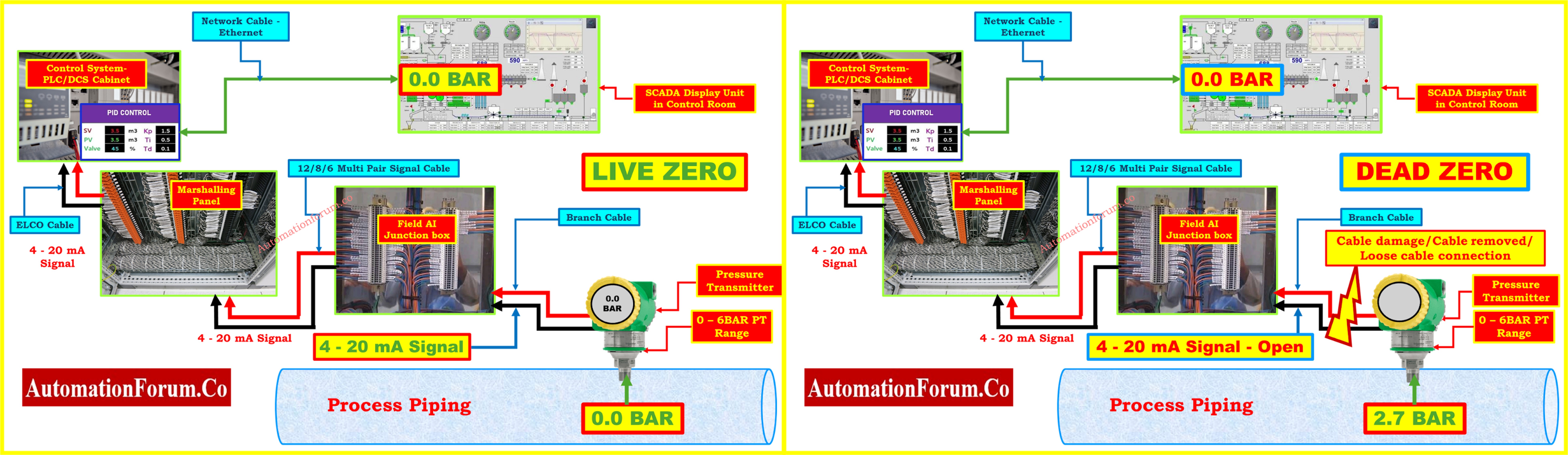
Both images provided serve as powerful educational tools to reinforce this concept visually:
- The LIVE ZERO image shows a healthy loop operating at 4 mA = 0 bar.
- The DEAD ZERO image shows a broken loop where the actual process value is 2.7 bar, but the control system reads 0.0 bar due to signal loss.
Always remember: Live Zero = Process Zero, Dead Zero = Fault.
Refer the below link to Diagnose Loop Issues Effectively with: How to do troubleshooting of a 4-20mA loop?
FAQ on LIVE ZERO and DEAD ZERO
What is the difference between Live Zero and Dead Zero?
Live Zero is a signal whereby the minimum value, denoting 0% of a process variable, exceeds 0 (e.g., 4 mA in a 4-20 mA loop). This guarantees that even with a zero process variable the loop remains powered.
On the other hand, dead zero indicates that the signal value starts at 0 mA, so zero current can either indicate that the process variable is at 0% or that there is a malfunction such a wire break or transmitter failure making diagnosis challenging.
What is the difference between 4-20 mA and 0-20 mA signal systems?
Differentiating between an actual 0% process value and a system fault becomes difficult in a 0-20 mA system since the current can drop below 0 mA. This can lead to issues, particularly with loop-powered (2-wire) transmitters, in which a zero current would cause the transmitter to stop working.
By comparison, a 4-20 mA system preserves 4 mA as the minimum current. This maintains the transmitter running and lets systems identify open circuits when the signal drops below 4 mA, therefore guaranteeing dependability and simple fault diagnostics.
What does “Live Zero” and “Dead Zero” mean in sensors?
A sensor signal reading 0 may indicate:
- Known as Live Zero, the process value is actually zero that is, 0 RPM or 0 pressure.
- Dead Zero is the signal lost via sensor error, power outage, or cable disconnection.
Analog signal designs such as 4-20 mA enable differentiating between these two states. Should the signal be 4 mA, the system is in good condition; the zero reading is valid. Should the signal be 0 mA, the loop most certainly has a fault.
What other signal ranges use Live Zero principles?
Apart from 4–20 mA, some popular live-zero signal designs consist in:
- 1-5 V
- 10-50 mV
In all these circumstances, the lowest signal level which represents 0% of the process variable is still above zero, therefore preserving loop integrity and enabling fault detection.
What is the purpose of Live Zero?
Live Zero serves several key functions:
- It ensures that a transmitter stays powered even in cases of minimum measured value.
- It enables one to differentiate between a real zero process value and loop issues like wire breaks.
- It supports two-wire transmitters run on loops, therefore saving the need for separate power connections.
What does “Zero Live” mean in two-wire systems?
Why is 4-20 mA the industry standard?
There are several reasons why 4-20 mA has become the dominant signal standard:
- Simplicity: Simple for wiring and configuring.
- Long-distance performance: Current signals do not degrade over distance like voltage signals.
- Reliability: Open circuits or wire breaks are easily identifiable..
- Power plus signal in one loop: Enables two-wire loop-powered transmitters.
- Interference resistance: Less susceptible to electrical noise compared to voltage signals.
Why choose a Live Zero system like 4-20 mA?
- It enables fault detection should the signal drop below 4 mA.
- Maintains the system powered for diagnostics and signal integrity.
- Supports both hazardous and essentially safe area applications.
- Gets zero readings clear of uncertainty.