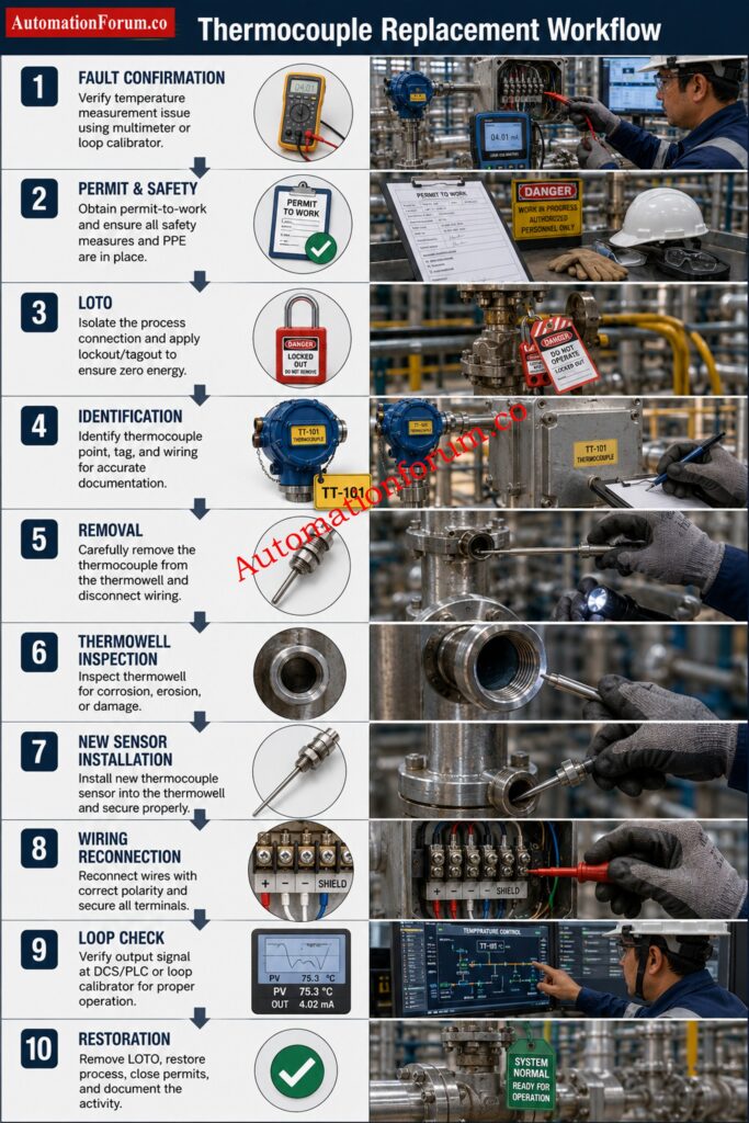
- Introduction to Thermocouple Replacement in Process Areas
- Purpose and Scope of the Thermocouple Replacement Procedure
- When a Thermocouple Should Be Replaced
- Pre Job Planning and Work Preparation
- Required Tools, Materials and PPE for Thermocouple Replacement
- Permit to Work Requirements for Thermocouple Maintenance
- Job Safety Analysis and Risk Assessment
- Control System Preparation Before Removing the Thermocouple
- Isolation and Lockout Tagout Procedure
- Field Verification Before Thermocouple Removal
- Thermocouple Wiring Disconnection Procedure
- Safe Removal of the Faulty Thermocouple
- Thermowell Inspection and Verification
- Installation of the New Thermocouple
- Reconnection of Thermocouple Wiring
- Post-Installation Verification and Loop Testing
- Alarm and Interlock Restoration After Thermocouple Replacement
- Loop Functional Check and Acceptance Criteria
- System Normalization and Return to Service
- Post Start-Up Monitoring After Thermocouple Replacement
- Documentation and Maintenance Records
- Abnormal Condition Escalation
- Spare Replenishment Procedure
- Common Mistakes During Thermocouple Replacement
- Best Practices from Experienced Instrumentation Engineers
- Critical Lessons Learned from Thermocouple Replacement Activities
- FAQ on Thermocouple Replacement Activities
Introduction to Thermocouple Replacement in Process Areas
Thermocouples are one of the most widely used temperature sensors in process industries because they are rugged, fast responding, and suitable for high-temperature applications. In refineries, petrochemical plants, power stations, chemical units, and pharmaceutical facilities, a faulty thermocouple can quickly affect process control, product quality, energy efficiency, and equipment protection.
A wrong temperature signal may lead to poor combustion control, unstable reactor conditions, overheated equipment, unsafe operating conditions, and nuisance trips. In severe cases, replacing a thermocouple incorrectly can create a new fault even after the original problem has been removed. That is why thermocouple replacement must be carried out in a disciplined sequence, with attention to safety, isolation, verification, installation, and final loop checking.
Where thermocouples are installed in thermowells, maintenance is generally safer and more practical because the sensor can be replaced without direct process exposure. Even then, thermowell condition, insertion length, and proper seating remain critical for accuracy and reliability.
Purpose and Scope of the Thermocouple Replacement Procedure
This procedure defines the safe method for replacing a faulty thermocouple in a process area. It applies to thermocouples installed in thermowells, terminal heads, junction boxes, and associated field wiring connected to PLC, DCS, SIS, or monitoring systems.
Stop Making This Costly Wiring Mistake Every Engineer Faces: Thermocouple Wire vs. Thermocouple Extension Wire: The Complete Guide for Instrumentation Engineers
When a Thermocouple Should Be Replaced
A thermocouple should not be replaced just because the indication looks unusual once. The fault must be confirmed by checking the signal, the field wiring, the junction box, the extension cable, and the control system input.
Common Signs of a Faulty Thermocouple
Common signs include:
- Open circuit or faulty sensor
- Temperature reading stuck at one value
- Sporadic Variations
- Apparent drift or slow drift
- Incorrect temperature reading relative to neighboring instruments
- Terminal loose connection
- Ingress of moisture in junction box or head assembly
- Corrosion on terminal or sheath
- Mechanical damage to probe or lead wire
- Burnout from process overheating
- Damaged extension cable or incorrect cable material
How to Confirm the Fault Before Replacement
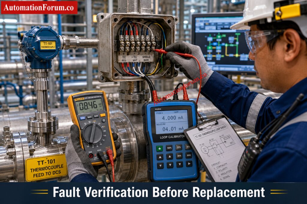
Check the signal at the transmitter or input card before replacing the sensor; check terminals, continuity, compare with a good reference and determine if the fault is in the sensor or the wiring line. This avoids unnecessary removal of a healthy thermocouple.
Refer the below link for the Testing a Thermocouple With a Multimeter: A Complete Field Guide for Instrumentation Engineers
Pre Job Planning and Work Preparation
Good thermocouple replacement starts before the technician reaches the field. Review all available documentation and confirm the instrument tag and service conditions
Responsibilities of Operations and Instrumentation Personnel
- Operations Personnel: Confirm process readiness, approve required bypasses, and coordinate plant conditions during maintenance.
- Instrumentation Technician: Isolate, replace, wire, verify and restore according this method.
- Instrumentation Lead: Check permit compliance, job preparedness, spare availability and final work completion.
- Control Room Operator: (no text) Monitor Process Conditions Implement Approved Bypasses and Verify Signal Restoration after Maintenance.
Review of P&ID, Instrument Index, Loop Diagram and Datasheet
Check the following:
- P&ID
- Instrument index
- Loop diagram
- Hook-up drawing
- Cause and effect matrix
- Instrument datasheet
- Control narrative
Verify Instrument Details
Confirm:
- Tag number
- Service description
- Thermocouple type
- Measuring range
- Insertion length
- Thermowell type
- Junction type
- Process conditions
Spare Thermocouple Verification Before the Job
Before opening the work order, check:
- Thermocouple type correct
- Proper sheath material
- Insertion length correct
- Correct process connection
- Right polarity
- Certificate of calibration, if relevant
- Compatibility of material with process fluid
Wrong choice of thermocouple can lead to substantial measurement errors, sluggish response, or premature failure due to chemical attack, vibration, or temperature mismatch.
Instantly Convert Sensor Signals Without Complex Calculations: Thermocouple Voltage ↔ Temperature Calculator
Required Tools, Materials and PPE for Thermocouple Replacement
Tools and Materials Checklist
- Correct replacement thermocouple
- Approved thermocouple extension cable
- Multimeter
- Temperature calibrator or loop calibrator
- Insulated hand tools
- Terminal lugs and ferrules
- Cleaning materials
- Flashlight
- Portable communication device
- Approved PPE
- Calibration certificate where applicable
Personal Protective Equipment Requirements
Select PPE based on the task and the area hazard.
Required PPE
- Safety helmet
- Safety glasses
- Face shield
- Flame resistant clothing
- Heat resistant gloves
- Chemical resistant gloves
- Cut resistant gloves
- Safety shoes
- Hearing protection
- Respiratory protection where required
Why Heat Resistant Gloves Are Important
Thermocouple removal often exposes technicians to residual process heat. Even after isolation, the thermowell and sensor housing may remain hot enough to cause burns. Heat resistant gloves help prevent:
- Contact burns during sensor removal
- Hand injury from hot thermowell surfaces
- Accidental contact with heated metal parts
- Reduced grip due to sudden heat exposure
The Accuracy Secret Many Temperature Systems Still Miss: Why Thermocouple Reference Junction Compensation(CJC) is Essential for Accurate Temperature Measurement ?
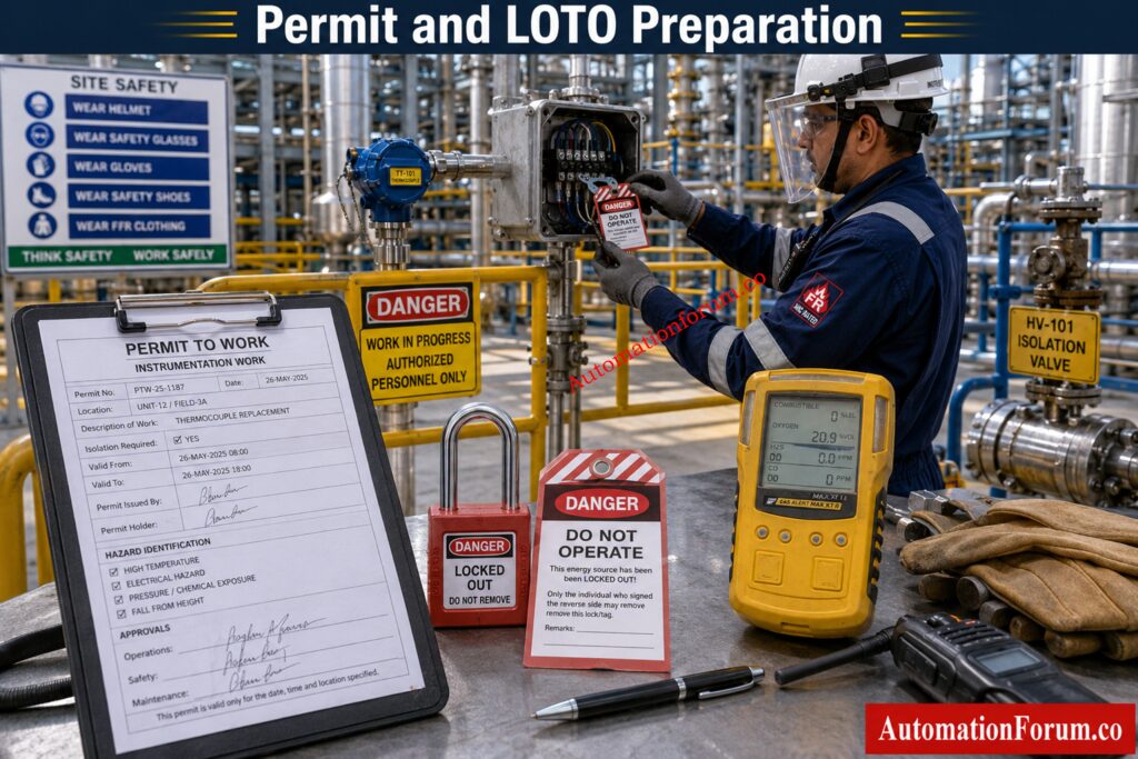
Permit to Work Requirements for Thermocouple Maintenance
No thermocouple replacement in a process area should begin without valid permits. The permit system protects both personnel and the plant.
Required Permits for Process Area Work
Depending on the job, obtain:
- Instrument maintenance permit
- Electrical isolation permit
- Hot work permit, if applicable
- Cold work permit
- Area entry permit
- Confined space permit, if applicable
Permit Checks and Validity Verification
Verify:
- Permit validity period
- Approval hierarchy
- Exact job scope
- Work location
- Identified hazards
- Control measures
- Responsible signatories
If the scope of work changes, cease work and revalidate the permission before starting work.
Turn Raw Sensor Signals Into Reliable Process Values: How to Convert Thermocouple Millivolts to Temperature: A Step-by-Step Guide
Job Safety Analysis and Risk Assessment
Carry out a job safety analysis before starting.
Hazards During Thermocouple Replacement
- Hot surfaces
- High process temperature
- Steam lines
- Chemical exposure
- Toxic gas exposure
- Rotating equipment nearby
- Slips, trips, and poor access
- Electrical hazards
Control Measures and Work Area Safety
- Barricade the work area
- Confirm isolation boundaries
- Maintain clear communication with operations
- Perform gas testing where required
- Keep emergency response arrangements ready
- Ensure escape routes are not blocked
A thermocouple job may look small, but in a live process area, the surrounding hazards are often more serious than the instrument itself.
Only Experts Can Score High On This Challenge: Advanced Thermocouple Knowledge Quiz: Principles, Types, and Industrial Applications
Control System Preparation Before Removing the Thermocouple
Before disturbing the sensor, coordinate with the control room or operating team.
Signal Bypass Requirements
Depending on plant philosophy, apply temporary bypasses for:
- Alarm bypass
- Trip bypass
- Shutdown bypass
- Interlock bypass
Controller Actions Before Maintenance
- Put affected loop in manual mode if required
- Break cascade if the signal is part of a control structure
- Freeze output if necessary
- Maintain active process monitoring
Removing a thermocouple without preparing the control system can create false alarms, process upset, or unwanted shutdowns. The operator must know exactly what is being bypassed and when it will be restored.
Avoid Conversion Errors That Cause Major Process Issues: Converting Thermocouple Millivolts to Temperature: Methods and Examples
Isolation and Lockout Tagout Procedure
Thermocouple replacement often involves low-voltage circuits, but low voltage does not mean no hazard. Follow full lockout and tagout discipline.
Electrical Isolation Steps
- Identify the correct power source.
- Open the isolator.
- Remove fuse if applicable.
- Apply lock.
- Apply tag.
- Record the isolation in the permit or lock register.
Verification of Zero Energy
Confirm isolation by:
- Voltage testing
- Loop verification
- Dead testing
Never trust a switch position alone. Prove zero energy before touching wiring.
LOTO Documentation and Records
Maintain:
- Lock register entry
- Isolation certificate
Critical Startup Checks That Prevent Future Temperature Failures: Thermocouple Commissioning Checklist
Field Verification Before Thermocouple Removal
Do not remove any instrument until you have positively identified it.
Positive Identification of the Correct Loop
- Correct tag number
- Correct thermocouple
- Correct cable identification
- Correct junction box
- Correct DCS or PLC point
A wrong removal can create a new control problem in a different loop. In many plants, this is one of the most common maintenance errors.
Hold Points and Stop Work Conditions
Stop the work immediately and inform supervision if:
- Incorrect thermocouple tag is identified
- Process isolation cannot be confirmed
- Unexpected high temperature is detected
- Thermowell damage is observed
- Wrong spare thermocouple is supplied
- Junction box contains unidentified wiring
- Gas testing results are unsafe
- Permit conditions are violated
- Abnormal process conditions develop during maintenance
Use This Proven Checklist Before Replacing Any Sensor: Check List: How to Troubleshoot a Thermocouple?
Thermocouple Wiring Disconnection Procedure
Before Disconnecting the Sensor
- Take a clear photograph of the terminal arrangement if possible or make proper marking and keep record of connection data.
- Verify terminal numbers
- Check polarity
- Mark conductors if required
Cable Removal and Terminal Inspection
- Loosen the terminal carefully
- Protect conductor ends from damage
- Inspect the cable condition
- Check for extension cable deterioration
Why Thermocouple Polarity Matters
Thermocouple polarity is critical. Reversed polarity may not always create a complete failure, but it can give unstable or misleading readings. Use the correct extension wire for the thermocouple type.
Safe Removal of the Faulty Thermocouple
Removal Steps from Thermowell or Process Connection
- Confirm the process connection is safe to open.
- Gradually loosen fitting.
- Remove the sensor gently.
- Do not bend the probe
- Do not force the sensor if it is stuck.
- Protect the thermowell from mechanical damage.
Key Hazards During Sensor Removal
- Residual heat
- Seized sensor inside thermowell
- Corrosion on threads or fittings
- Mechanical stress during extraction
If the probe does not come out smoothly, stop and inspect. Forcing the sensor may damage the thermowell or break the replacement job into a larger repair.
Can You Pass This Advanced Instrument Selection Challenge? – Quiz on RTD and Thermocouple Selection for Instrumentation Design Engineers
Thermowell Inspection and Verification
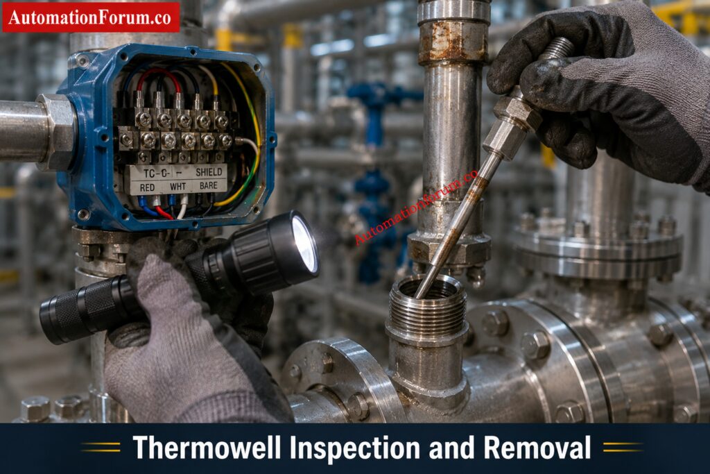
Thermowell inspection is not optional. A new thermocouple installed into a damaged thermowell will still give poor results.
Mechanical Condition of the Thermowell
Inspect for:
- Corrosion
- Erosion
- Pitting
- Cracks
Internal Cleanliness and Obstruction Check
Check for:
- Bore cleanliness
- Obstructions
- Moisture ingress
- Rust or debris inside the well
Dimensional Verification and Insertion Length
Confirm:
- Thermowell insertion length
- Bore diameter
- Sensor fitment
- Thread condition
Insertion length directly affects response time and measurement accuracy. If the sensor tip is not properly located in the well, the reading can lag the real process temperature. A sufficient depth of immersion and correct disposition of the thermowell are necessary for a stable measurement of temperature.
Thermowell Integrity Assessment
Where plant procedures require, inspect the thermowell for signs of thinning, vibration damage, cracking, excessive corrosion, or process erosion. A damaged thermowell can fail mechanically and may become a process safety hazard. Replace the thermowell if its integrity is doubtful.
Avoid Expensive Selection Errors With These Expert Tips: How to Select the Right Thermocouple for Temperature Measurement Applications?
Installation of the New Thermocouple
Pre-Installation Checks
- Verify tag number
- Confirm thermocouple type
- Inspect the physical condition
- Check calibration or supplier documentation
Correct Sensor Insertion and Seating
- Insert the sensor carefully.
- Verify correct insertion depth.
- Ensure full seating.
- Tighten the process connection to the correct torque.
- Confirm the probe is not under mechanical stress.
Correct immersion length, correct engagement of the thermowell. If the sensor is slack or not installed properly, thermal contact can be weak and readings can be unstable.
The Calibration Technique That Simplifies Sensor Simulation: How to simulate RTDs and Thermocouples using Multifunction calibrator?
Reconnection of Thermocouple Wiring
Correct Terminal Connection and Polarity
- Terminate on the correct terminal
- Maintain correct polarity
- Verify shield grounding
- Inspect cable glands
- Check all terminal tightness
Thermocouple polarity and proper extension cable selection are essential for signal integrity and measurement accuracy.
Common Wiring Mistakes to Avoid
- Reversed polarity
- Loose terminal screws
- Wrong extension wire type
- Missing shield termination
- Damaged gland sealing
- Cross-wiring in junction box
Each of these can create noise, drift, or complete loss of indication.
Post-Installation Verification and Loop Testing
Local Verification at the Field Device
- Check terminal voltage
- Confirm continuity
- Measure sensor resistance and millVolt mV where applicable
- Inspect the junction box again
Control System Verification in DCS, PLC, or SCADA
- Confirm DCS indication
- Check PLC signal if applicable
- Verify SCADA display
- Observe trend stability
Functional Verification and Signal Stability Check
- Compare with nearby temperature elements
- Confirm process temperature consistency
- Watch for signal stabilization after installation
The goal is not only to restore indication, but to restore trustworthy indication.
Alarm and Interlock Restoration After Thermocouple Replacement
Before normal operation is resumed, remove all temporary bypasses in a controlled manner.
- Restore alarm logic
- Restore trip logic
- Restore interlocks
- Inform operations before normalization
Do not leave bypasses active after the repair is complete. This is a process safety risk.
Loop Functional Check and Acceptance Criteria
End-to-End Loop Verification
Perform end-to-end loop verification.
- Field sensor
- Marshalling terminals
- I/O channel
- Controller input
- HMI indication
Acceptance is achieved only when the signal is stable, correctly scaled, and consistent across the control system.
Acceptance Criteria for Successful Replacement
The replacement shall be considered successful only when:
- Correct thermocouple type is installed
- Correct insertion length is verified
- Polarity is confirmed
- Terminal connections are secure
- Signal is stable at the DCS or PLC
- No active alarms remain due to maintenance
- All temporary bypasses are removed
- Loop indication is consistent with process conditions
- Required documentation has been completed
System Normalization and Return to Service
Once the loop is verified:
- Remove locks
- Restore power
- Return controller to automatic mode
- Inform operations
- Confirm stable process operation
Normalization should be deliberate. A rushed return to service can undo the quality of the maintenance job.
Post Start-Up Monitoring After Thermocouple Replacement
After restoration, monitor the temperature indication for a suitable observation period.
Verify:
- Stable trend response
- No intermittent signal loss
- No abnormal fluctuations
- No unexpected alarms
- Normal controller performance
- Consistency with nearby temperature measurements
Any abnormal behavior shall be investigated before the work order is closed.
Documentation and Maintenance Records
Record the work properly.
Failure Details and Root Cause Notes
- Failure details
- Root cause observations
- Replacement details
- Calibration data
- Spare consumption
CMMS Updates and Asset History
- Close the work order
- Update asset history
- Record reliability observations
- Note recurring failure patterns
Good records help engineering teams identify chronic problems and improve future maintenance planning.
Discover Which Sensor Technology Fits Your Application Best: Choosing Between Thermocouples and RTDs: A Practical Guide for Temperature Sensing
Abnormal Condition Escalation
Escalate the issue to supervision and engineering if:
- The replacement thermocouple fails immediately after installation
- The thermowell is damaged or severely corroded
- The process temperature remains inconsistent after replacement
- Repeated thermocouple failures occur in the same service
- Wiring defects extend beyond the local installation
- Control system input problems are suspected
Do not repeatedly replace sensors without determining the actual root cause of failure.
Spare Replenishment Procedure
After the job, replenish the spare stock.
- Check minimum inventory level
- Trigger reorder if required
- Classify critical spares correctly
- Update inventory records
Immediate replenishment prevents delays during the next shutdown or emergency repair.
Follow These Proven Steps For Reliable Sensor Accuracy: 8 Steps Calibration Procedure for Thermocouple
Common Mistakes During Thermocouple Replacement
| Mistake | Consequence |
| Wrong thermocouple type installed | Incorrect temperature reading |
| Wrong polarity connection | Reversed or inaccurate signal |
| No bypass applied | Alarm, trip, or shutdown risk |
| LOTO not verified | Electrical or process hazard |
| Wrong insertion length | Poor response and accuracy |
| Thermowell not inspected | Hidden mechanical failure remains |
| Wiring not labeled | Cross connection and confusion |
| Calibration certificate not checked | Unverified spare used |
| Improper PPE used | Injury from heat or chemicals |
| Alarm restoration missed | Unsafe operating condition |
| Loose terminal connection | Intermittent signal |
| Wrong extension cable | Signal error and drift |
| Sensor forced into well | Mechanical damage |
| Missing field photo record | Difficult troubleshooting later |
| CMMS not updated | Loss of maintenance history |
Best Practices from Experienced Instrumentation Engineers
- Confirm the fault before replacement.
- Compare the reading with a nearby instrument.
- Review the loop diagram before going to the field.
- Always check thermocouple type and polarity.
- Use the correct extension cable, never a random spare.
- Photograph the existing wiring before removal.
- Inspect the thermowell every time the sensor is replaced.
- Verify insertion length against the datasheet.
- Never force a sensor into the well.
- Keep the work area barricaded.
- Inform the control room before disturbing the loop.
- Use the correct PPE for hot process areas.
- Check terminal tightness after reconnection.
- Confirm shield grounding practice.
- Verify indication at the DCS and locally.
- Watch for unstable readings after startup.
- Restore all bypasses before handing over.
- Record the failure cause, not only the replacement.
- Keep the spare stock organized by thermocouple type.
- Treat every temperature loop as a process safety item, not only an instrumentation item.

Critical Lessons Learned from Thermocouple Replacement Activities
A thermocouple replacement in a process area must be handled as a controlled maintenance activity, not a simple sensor swap. The correct workflow starts with permit approval and safety preparation, then moves through control system bypassing, isolation, positive identification, careful removal, thermowell inspection, correct insertion length verification, proper installation, accurate wiring, signal validation, loop checking, normalization, documentation, and spare replenishment.
When each step is completed in sequence, the result is safe personnel work, stable process operation, and reliable temperature measurement. When steps are skipped, the plant often pays for it later through false readings, nuisance trips, repeat maintenance, or unsafe operating conditions.
FAQ on Thermocouple Replacement Activities
How Do You Replace a Thermocouple?
First confirm the fault, then isolate the loop, apply LOTO, remove the old sensor carefully, inspect the thermowell, install the correct replacement, reconnect wiring with correct polarity, and verify the signal in the control system. The job should end only after loop checking, alarm restoration, and documentation are completed.
When Should a Thermocouple Be Replaced?
A thermocouple should be replaced only after the fault has been confirmed. Common signs include an open circuit, frozen temperature reading, erratic signal, drift, corrosion, moisture ingress, damaged wiring, or incorrect temperature indication.
What Is the Correct Installation of a Thermocouple?
Correct installation requires the proper thermocouple type, insertion length, polarity, and thermowell engagement. The sensor should be fully seated, terminals securely tightened, and the signal verified for stable operation after installation.
Do I Need a Professional for Thermocouple Replacement?
Yes, thermocouple replacement in process plants should be performed by qualified instrumentation personnel. The work involves permits, isolation, wiring verification, thermowell inspection, loop testing, and safe restoration of the process.
How Much Does Thermocouple Replacement Cost?
The replacement cost depends on the thermocouple type, installation location, labor requirements, plant safety procedures, and whether additional repairs such as wiring or thermowell replacement are needed. Complex process-area jobs typically cost more than simple replacements.
How Long Does It Take to Replace a Thermocouple?
The time required depends on accessibility, permit requirements, isolation procedures, and testing requirements. A simple replacement may take less than an hour, while a process plant replacement involving verification and loop testing can take several hours.
Refer the below link for How to calibrate Thermocouple Transmitter?