- What is float type level switch?
- What is the construction and working principle of float switch?
- Step-by-Step Procedure for Installing Float Type Level Switches
- Step 1: Safety Procedures
- Step 2: Prepare Required Documentation
- Step 3: Inspection and Pre-installation Checks
- Step 4: Specification Check
- How do you install a float level switch?
- Step 5: Mechanical Installation of Float Type Level Switches
- Step 6: Electrical and Wiring Connections of Float Type Level Switches
- Step 7: Functional Testing of Float Type Level Switches
- Step 8: Commissioning and Final Checks
- Step 9: Final Testing and Handover
- Step 10:Final Additional Checkpoints
- Compliance with Reference Standards:
- Float Type Level Switch Installation Checklist – Downloadable
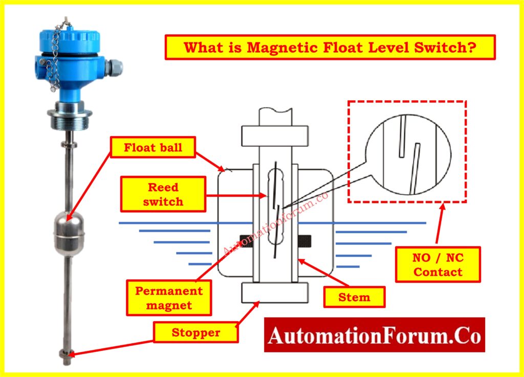
What is float type level switch?
The magnetic float level switch is made up of one or more reed switch components that are fixed inside a stem made of engineering plastic or stainless steel. The designated float ball(s), which are intended to move down the stem, have a permanent magnet inserted in the center. The buoyancy of the liquid allows the float ball to glide down the stem and travel up and down to a certain location marked by graduation rings.
The reed switch contact is triggered to open or close the circuit as the internal magnet of the float gets closer to it. Monitoring and controlling the liquid level can then be done with this on-off signal. The float positions for normally closed (N.C.) and normally open (N.O.) layouts are shown in the diagrams below.
What is the construction and working principle of float switch?
Click here for Mastering Level Measurement Technologies: A Comprehensive Guide
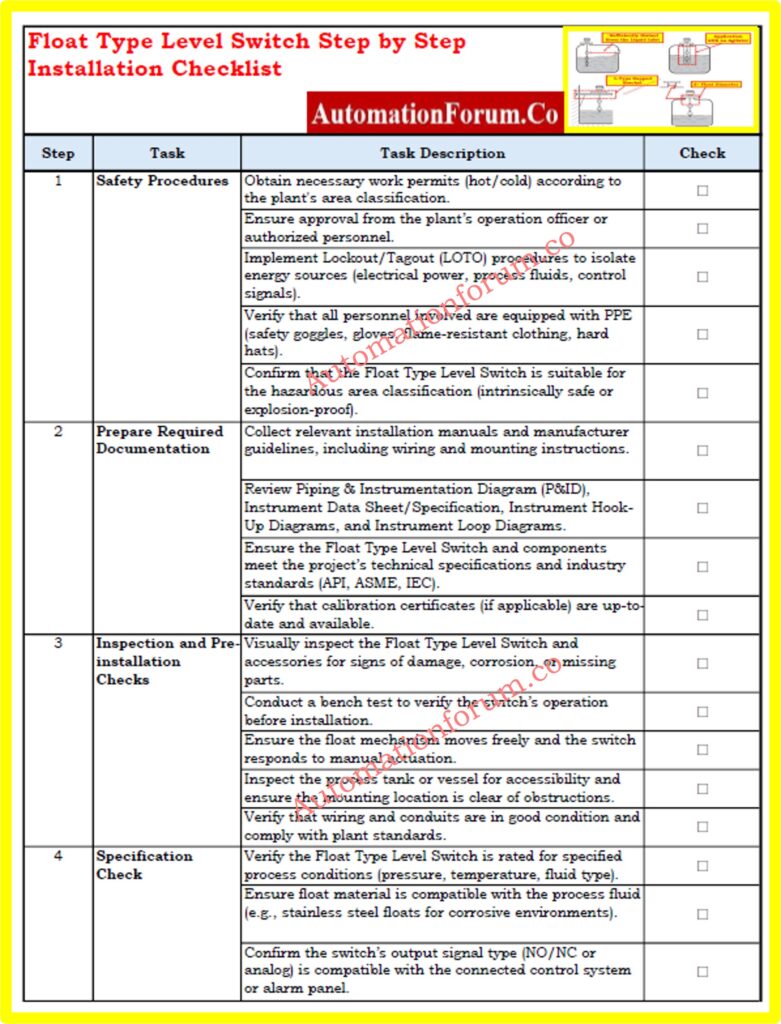
Step-by-Step Procedure for Installing Float Type Level Switches
Step 1: Safety Procedures
- Obtain necessary work permits, such as hot or cold work permits, according to the plant area classification. Approval from the plant’s operation officer or authorized personnel is required before starting any work.
- Implement Lockout/Tagout (LOTO) procedures to isolate all sources of energy, such as electrical power, process fluids, and control signals, ensuring personnel safety during installation.
- Ensure that all personnel involved in the installation are equipped with appropriate PPE, including safety goggles, gloves, flame-resistant clothing, and hard hats. Special precautions should be taken in hazardous environments.
- Verify that the Float Type Level Switch is suitable for the specific hazardous area classification (e.g., intrinsically safe or explosion-proof).
Step 2: Prepare Required Documentation
- Collect relevant installation manuals and guidelines provided by the manufacturer for the Float Type Level Switch, including wiring and mounting instructions.
- Review Piping & Instrumentation Diagram (P&ID), Instrument Data Sheet /Specification, Instrument Hook-Up Diagrams, and Instrument Loop Diagrams to confirm system integration and installation requirements.
- Ensure that the Float Type Level Switch and associated components meet the project’s technical specifications and industry standards (such as API, ASME, or IEC).
- Verify that calibration certificates for the switch, if applicable, are up-to-date and available.
Step 3: Inspection and Pre-installation Checks
- Perform a visual inspection of the Float Type Level Switch and related accessories for any signs of damage, corrosion, or missing parts that could affect performance.
- Conduct a bench test (if possible) to verify the switch’s operation before installation. Ensure that the float mechanism moves freely and the switch responds to changes in liquid levels by manual actuation.
- Inspect the process tank or vessel where the switch will be installed. Ensure the mounting location is accessible and clear of any obstructions or debris that could interfere with the installation.
- Ensure that wiring and conduits are in good condition, properly labeled, and comply with plant wiring standards to prevent electrical noise and damage.
Step 4: Specification Check
- Verify that the Float Type Level Switch is correctly rated for the specified process conditions, including pressure, temperature, and fluid type.
- Confirm that the float material is compatible with the process fluid to avoid corrosion or operational issues (e.g., stainless steel floats for corrosive environments).
- Additionally, ensure that the switch’s output signal type (e.g., NO/NC contacts or analog signal) is compatible with the input requirements of the connected control system or alarm panel.
Click here for What is a level switch and what are its types?
How do you install a float level switch?
Step 5: Mechanical Installation of Float Type Level Switches
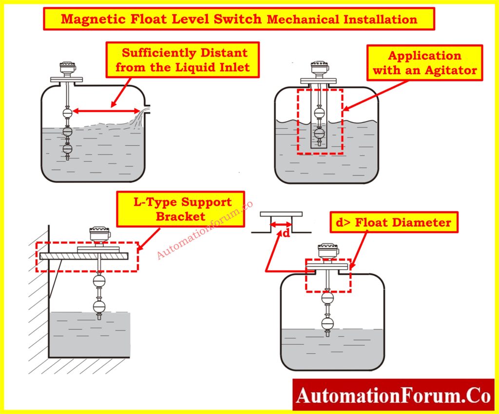
- Position the Float Type Level Switch in the designated mounting point on the tank or vessel. The mounting orientation should match the manufacturer’s recommendations (e.g., top or side mounting).
- Secure the switch using the appropriate mounting hardware, such as flanges, threaded connections, or brackets, ensuring it is properly aligned and fastened.
- Ensure that the float is positioned correctly and has enough clearance to move freely within the tank or vessel without contacting walls or obstructions.
- For side-mounted switches, confirm the installation height is set to the correct operating level for high or low-level detection, as indicated in the installation drawings.
- Ensure that the Float Type Level Switch is mounted at a location that is sufficiently distant from the liquid inlet. This prevents strong liquid fluctuations from causing inaccurate output signals, as turbulent conditions near the inlet can lead to erroneous readings.
- If the Float Type Level Switch is installed in an application with an agitator, it is recommended to use a pipe shield or similar device to stabilize the switch operation. This will help normalize the switch actuation by minimizing the impact of turbulence and agitation on the float’s movement, ensuring accurate and reliable performance.
- When mounting the Float Type Level Switch on a concrete wall tank, it is advisable to use an L-type support bracket. This will provide additional stability and ensure secure installation, as illustrated in the figure above.
- For installation, it is recommended to choose a standpipe with a diameter larger than the float ball. This allows for sufficient space, ensuring that the float ball can move freely without restrictions and operate accurately within the standpipe.
Step 6: Electrical and Wiring Connections of Float Type Level Switches
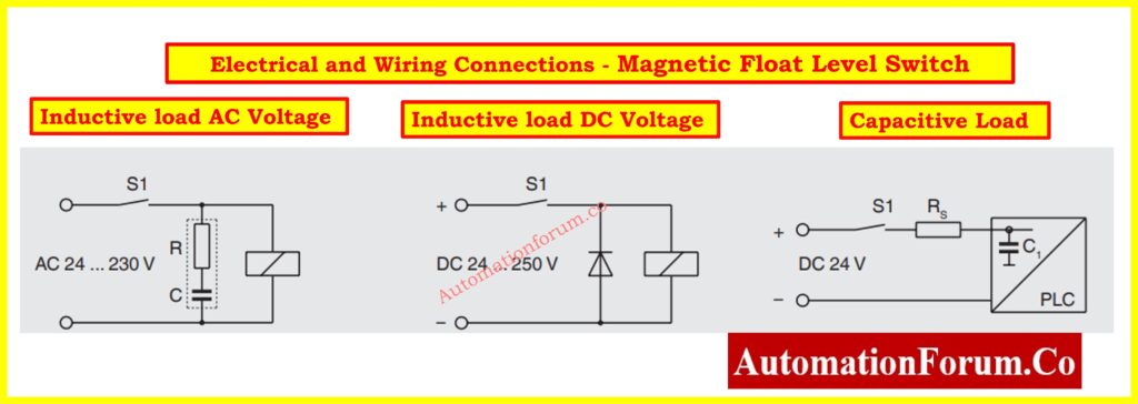
- Connect the electrical wiring according to the manufacturer’s wiring diagram, ensuring that the connections are made to the correct switch contacts, typically either Normally Open (NO) or Normally Closed (NC), based on the application’s requirements.
- Connect the electrical wiring of the Float Type Level Switch according to the manufacturer’s wiring diagram, ensuring proper connection to the switch contacts (NO/NC). Depending on the type of load and voltage, follow these guidelines:
- For inductive AC loads: Use the appropriate components, such as a resistor (R) and capacitor (C), to suppress potential inductive spikes when switching AC voltages between 24 and 230 V.
- For inductive DC loads: Ensure the wiring includes a flyback diode across the relay coil to prevent voltage spikes that could damage the switch, especially when handling DC voltages from 24 to 250 V.
- For capacitive loads: Include a series resistor (Rs) to limit inrush current, particularly when interfacing with programmable logic controllers (PLCs) or other electronic devices sensitive to capacitive loads.
- Use suitable cable glands or conduit fittings to protect the wiring from external elements such as moisture, dust, and corrosive substances, which could compromise the integrity of the connection over time.
- Properly ground the wiring to mitigate the risk of electrical noise or signal interference, which is especially important in high-voltage environments. Effective grounding ensures reliable signal transmission and prevents potential malfunctions or erroneous readings.
- Integrate the Float Type Level Switch into the plant’s control system, alarm panel, or emergency shutdown (ESD) system by wiring it to trigger the appropriate responses under specific conditions.
- This could include alerts for operators or automated shutdowns when high or low-level thresholds are detected, enhancing safety and ensuring rapid response to abnormal conditions
Step 7: Functional Testing of Float Type Level Switches
Simulate Liquid Levels:
- Simulate different liquid levels in the tank to assess the switch’s response. Carefully observe whether the switch activates and deactivates at the designated high and low levels.
Verify Output Signals:
- Check that the switch’s output signals (NO/NC) are accurately received by the plant’s control system or alarm panel.
- This ensures proper communication between the switch and monitoring systems.
Confirm Alarm Accuracy:
- Test the accuracy of high and low-level alarms by manually triggering the switch or using a liquid level simulator.
- Verify that alarms are activated at the correct levels and are functioning as intended.
Calibration Check:
- Perform calibration of the Float Type Level Switch if necessary. Adjust the settings to ensure that the switch activates and deactivates at the specified levels, aligning with the operational requirements.
Test ESD System Integration:
- Ensure that any trip contacts connected to the Emergency Shutdown (ESD) system operate correctly.
- Trigger the switch to confirm that the appropriate emergency actions are initiated when high or low-level conditions are detected.
Document Results:
- Record the results of the functional tests, including any adjustments made during calibration, to maintain an accurate history of the switch’s performance and compliance with operational standards
Step 8: Commissioning and Final Checks
Performance Monitoring:
- Observe the Float Type Level Switch under actual operating conditions to verify its performance.
- Ensure that the float moves freely and that the switch triggers at the specified levels without any hindrance.
Communication Testing:
- Test the communication between the Float Type Level Switch and the Distributed Control System (DCS), Programmable Logic Controller (PLC), or SCADA system.
- Confirm that accurate level readings are transmitted and displayed correctly within the control system.
Final Inspection:
- Conduct a comprehensive final inspection of the installation.
- Ensure that all connections are secure, wiring is properly fastened, and the area around the switch is free from obstructions or hazards that could interfere with its operation.
Documentation Updates:
- Update all relevant documentation, including Instrument Loop Diagrams, wiring schematics, and calibration records, to accurately reflect the installation and configuration of the Float Type Level Switch.
- Ensure that all changes are well-documented for future reference.
Commissioning Report Preparation:
- Prepare a detailed commissioning report that includes the results of functional tests, system integration details, and any observations made during the installation process.
- This report serves as a valuable resource for future maintenance and operational assessments.
Step 9: Final Testing and Handover
- Conduct a final system test to ensure the Float Type Level Switch operates correctly under normal process conditions.
- Verify that all alarms, control signals, and safety shutdown functions are working as intended.
- Submit the commissioning report to the project manager or responsible authority, detailing the installation, testing, and final handover status.
- Ensure that all work permits are closed, and the plant’s safety protocols are re-confirmed after installation.
Step 10:Final Additional Checkpoints
- Ensure that all tools and equipment used during installation are accounted for and removed from the site.
- Review operator training requirements to ensure that personnel are knowledgeable about the Float Type Level Switch’s operation and maintenance.
- Confirm that a maintenance schedule is established for regular checks and calibration of the Float Type Level Switch.
- Perform a risk assessment post-installation to identify any potential hazards related to the switch’s operation within the system.
- Review feedback from operators after the installation and initial operation to identify any issues or areas for improvement.
Compliance with Reference Standards:
- Ensure that the Float Type Level Switch installation complies with all relevant industry standards and regulations, such as:
- API (American Petroleum Institute) for installation in oil and gas applications.
- ASME (American Society of Mechanical Engineers) for mechanical integrity.
- IEC (International Electrotechnical Commission) for electrical safety and performance.
- ISO (International Organization for Standardization) standards applicable to measurement and control devices.
- Review the manufacturer’s guidelines and certifications to verify that the switch meets the required safety, performance, and quality standards.
Float Type Level Switch Installation Checklist – Downloadable
This checklist provides a step-by-step guide for the proper installation, testing, and commissioning of Float Type Level Switches. It helps ensure the device operates efficiently and meets all safety and technical requirements. Follow each step to complete your installation safely and accurately.
You can download the detailed checklist in Excel format from the link below:
Click here for more Essential Instrumentation activities Checklists