- What is P&ID?
- What is included in P&ID?
- What is not included in P&ID?
- Who is responsible for P&ID?
- What is P&ID used for?
- What are the types of symbols used in P&ID?
- Signals and line symbols :
- Function symbols :
- Piping components symbols :
- Valve symbols :
- Actuator type for control valves :
- Position status of control valve :
- Equipment and process vessels symbols :
- Denomination Equipment and Instruments:
- How to read P&ID?
- Identification Letters :
- Location and type of mounting identification :
- For computing functions below symbols were used in the P&ID:
- Typical I/O symbols :
- Instrument Identification – Tagging & Numbering :
- Contents of line Specification:
- The Example pipeline specification explained in the P&ID is shown below:
- Sample closed loop P&IDs:
- What is the difference between PFD and P&ID?
- Distinction between PFD and P&ID:
What is P&ID?


What is included in P&ID?
Process requirement :
- All line and flow direction in process flow diagram as in PFD
- Equipments not shown in PFD like isolation and relieving system, minimum flow of pump, compressor anti surge flow
- Maintenance, operation, pre-commissioning, commissioning, and startup components.
- Showing how the liquid flowing from tank to pump and distributed to others in equipments/components
Piping :
- All lines for normal operation, special operation, start-up, shutting down, emergency and maintenance with piping components.
- Information about each line: line number, size, piping service class, fluid symbol and insulation
- All mechanical components with tag numbers
Instrumentation :
- Instrumentation system used for monitoring, controlling, recording, emergency shutdown, sequential control, interlock, and automatic start/stop.
- Alarm system, ESD and control system inputs
- The type, size, and configuration of field instruments such control and shutdown valves and their failure status
- All Instrumentation components with tag numbers
- The set pressure of pressure relief valves with size
- Type of signal like pneumatic, hydraulic, capillary tubing, electric, software link
Others :
- Battery limits between different process areas
- Changing responsibilities between Piping and Instrument, Contractor and Vendor
- Information about line breaks includes line number, plumbing service class, and insulation.
- Identification of equipment and subsystem which are delivered by vendors and contractors
What is not included in P&ID?
P&IDs does not includes
- The instrument root valves and electrical relays
- The pipe’s roots are uncovered.
- Connections and supports
- Location of equipment.
- Orientation and specs of valves
- Component specification.
- Nozzle Orientation.
- No colour code is specified.
Who is responsible for P&ID?
Designing P&IDs is the responsibility of process engineers, who collaborate with piping, instrumentation, electrical, and safety experts. For pipeline engineers, P&ID serves as the foundational document for selecting materials and determining pipe routing.

Users must keep the P&ID up to date throughout operation of process plant, so that it always displays the actual plant conditions. When a physical change is performed, it should be updated so that the unit may continue to operate safely under the specified process conditions and stay consistent with codes, standards, and specifications.
P&ID are usually created by design engineers who are designing a manufacturing process for a physical plant.
What is P&ID used for?
- Provide a visual representation of the equipment’s valving, sensors, configuration, etc.
- Gives useful information to help in analyzing hazards related with process
- Helps to make operating procedures, schedules & procedures for maintenance activities
- Communicates the configuration of the equipment in a clear and concise way so that the operator can better understand the process and reduce the human errors
- Keeps track of the process’s current (as-built) state so that changes can be planned safely and effectively.
- P&ID is used to estimate the capital costs of a project.
- It is also used to make the specifications for EPC contracts.
- Plot plant is made by taking into account various inputs from P&ID and the physical site location.
- During the EPC (Engineering, Procurement, and Construction) phase, P&ID is used to make the layout for each unit.
- It is used to classify hazardous areas and make data sheets for equipment, valves, and instruments.
- P&ID is used to plan the layout of the pipes and prepare the bulk material take-off for the piping, electrical, instrumentation, and civil systems.
- It is a key document for reviews like HAZOP, SIL, and operability review.
- Provides useful information to start control system programming
- P&IDs are mostly used by field technicians, maintenance and process engineers, and operators to understand the process and how the instrumentation systems related to the process. It is also very useful for training the employees and contractors who are supposed to work in the process area.
What are the types of symbols used in P&ID?
There are three main kinds of symbols on P&IDs.
- Symbols for Equipment: Process operation units for mass transfer, heat transfer, momentum transfer, and chemical reactions.
- Symbols for piping: Have to do with pipes, valves, and connections.
- Symbols representing instruments: For measuring, monitoring, and controlling the operational parameter.
Signals and line symbols :
These symbols are used to figure out how the different parts of the process connect to each other and what kind of signal is being used. (Electrical, Pneumatic, Hydraulic, Data, etc.,)
Function symbols :


Piping components symbols :
These symbols show how the piping parts of the process are connected to each other.


Valve symbols :
The diagrams below depict the main symbols for the various types of manually-operated valves as well as the actuator details for automatically-operated valves.
Note the stems on the actuators that indicate a failed condition. This is a fantastic example of using characteristics to deliver vital information to operations.


Actuator type for control valves :

Position status of control valve :

Equipment and process vessels symbols :


Denomination Equipment and Instruments:
A few examples of equipment denominations are shown below.

How to read P&ID?
P&IDs are intended to reflect the plant’s design, operation, maintenance, and safety of the organization. Understanding how to read P&IDs improves your comprehension of the design intent. When you first see P&ID, you will notice a number of symbols representing equipment, valves, instruments, pipelines, and so on. These symbols vary from company to company and client to client, but only to a certain point. To understand them better, you should always ask or look at legends. For basic knowledge and usage, you can refer to the Instrument Society of America (ISA) symbols.
When reading, try to interpret the associated meaning:
- Where and how safety relief valves are used
- Power supply and backup pumps
- Lines for draining and venting
- What symbols are used to represent various valves and instruments?
- Whether the instrument is mounted in the field, primary or secondary,

The P&ID will indicate each instrument and how they are connected to one another using symbols and circles. Legends help you understand the symbols used on P&IDs.
Tag “numbers” are letters and numbers that are placed inside or close to an instrument to identify its type and purpose.
The below diagrams shows the tag description:

Identification Letters :
The below table shows different measuring, function and modifier identification letters:


Location and type of mounting identification :
The location of a physical device is based on whether or not there is a line. For example, if there is no line, it means that the instrument is in the field, close to the process.
Certain instruments are a part of a Distributed Control System (DCS), where a particular controller or indicator can be chosen from a many number of others and shown in one place (like a terminal screen).Tag numbers will be displayed for various types of equipment and instruments & Pipeline line numbers.
The instruments locations and mounting information are shown in below diagrams.


Some instruments are part of a Distributed Control System (DCS), where a specific controller or indicator can be chosen from many others but only shown in one place (like a terminal screen).
Circular elements represent discrete instruments.
A hexagon represents computer functions, and a triangle within a square represents programmable logic controller (PLC) functions.
For example DCS, PLC, computer based functions symbols are shown below.

For computing functions below symbols were used in the P&ID:

Typical I/O symbols :
Simple triangular symbols along interconnecting lines to help illustrate the I/O flow on a P&ID. The symbols in the figure below illustrate this.

When you see these symbols, remember that the I/O flow is always from the perspective of the control computer. As a result, all outputs (DO, AO) are generated by an output module and transferred to a field device. On the other hand, all DI and AI are signals from field devices that flow into an input module. Sometimes, other types of I/O are used that may need special transducer cards or network protocols. For example, a thermocouple uses the KT signal, which is a common type of signals
Instrument Identification – Tagging & Numbering :
The numbers on P&ID symbols in instrumentation diagrams correspond to the instrument tag numbers. Typically, these numbers correspond to a specific control loop, such as the temperature indicator and controller 123 in the diagram below.

For ExampleXYY CZZLL
- X represents a process variable to be measured. (T=temperature, F=flow, P=pressure, L=level)
- YY represents the type of instruments.
- C indicates the instrument area within the plant.
- ZZ designates the process unit number.
- LL designates the loop number.
For the instrument with tag number LIC 10005
- L means Level shall be measured
- IC means Indicating controller
- 100 means Process Unit no.100 in the area of no.1
- 05 means Loop number 5
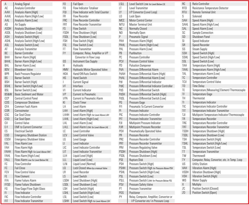
Below is a list of instrument abbreviations used in conjunction with P&ID symbols in instrumentation diagrams
Contents of line Specification:
Each line is labelled with the type of fluid, size, fluid Code, Material Code, Area Code, Line specification number, Schedule, Personnel Protection (Insulation), Heat Tracing etc.. Whether or not it is insulated, control loops with the bypass line, and so on.
The Example pipeline specification explained in the P&ID is shown below:
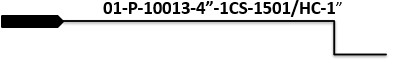
01 : Document Code
P : Process Fluid
100 : Area Code
13 : Line serial Number
4” : Size of line
1CS : Pipe Material CS grade1
1501 : #1501
HC 1” : Hard Core insulation, thk 1”.
Below picture shows the simple control loop P&ID diagram.

We have located the following instruments from the above P&ID. ie.
T123: Flow transmitter that is mounted in the field
FIC123: A flow-indicating controller that is mounted on a panel and is part of a control/display device.
TY123: Temperature I/P converter is mounted in field next to valve.
TT123: Temperature transmitter mounted in the field
TIC123: Temperature-indicating controller mounted in the field. Its output is interconnected to the setpoint (SP) of FIC123 through an internal software or data link.
YIC123: An event indicating a controller. All inputs and outputs are wired to an operator-accessible PLC. YIC usually denotes a controlled on/off valve.
Sample closed loop P&IDs:


We can understand how the SCADA, PLC, Local control system, field instrumentation system, and process equipment are interconnected in the process plant by looking at the P&ID below.

What is the difference between PFD and P&ID?
A PFD provides less detail than a P&ID and is only used to comprehend how the process works. In chemical and process engineering, the process flow diagram (PFD) is employed. This kind of diagram shows how chemical materials move through the process and what kinds of equipment are used. In other words, a process flow diagram will show us how the main parts of the system work together. Usually, a PFD only lists the most important equipment and nothing else. Also, it won’t show small parts, piping systems, pipe ratings, or pipe designations.
The Piping and Instrumentation Diagram (P&ID) contains additional information than the PFD. It includes both primary and secondary flows, control loops, and instrumentation. P&IDs are mostly utilized by process technicians and engineers.
In general, there is a distinct difference between PFDs and P&IDs:
PFDs are the foundational control records for the design of the process, including the mass, water, and energy balances.
P&IDs serve as the engineering design’s primary foundational control document
Distinction between PFD and P&ID:
| S. No. | Description | PFD | P&ID |
|---|---|---|---|
| 1 | Used during Construction | NO | YES |
| 2 | Show all process and service piping | NO | YES |
| 3 | Indicate presence of all controls | NO | YES |
| 4 | Shows all motors | NO | YES |
| 5 | Shows thermal insulations | NO | YES |
| 6 | Shows major equipment | YES | YES |
| 7 | Shows flow quantities | YES | NO |
| 8 | Shows stream compositions | YES | NO |
 shows how process equipment and instrumentation are connected. The post explains in detail.)