Table of Contents
- Loop checking is a crucial step in ensuring the proper functioning of pressure transmitter loops.
- This method statement outlines the detailed procedure for loop checking of a pressure transmitter loop to verify its accuracy and functionality.
- The loop checking process involves a series of steps aimed at testing the integrity of the loop, verifying the calibration of the pressure transmitter, and ensuring that it responds accurately to applied pressure changes.
Step 1: Tools and Equipment Required for Loop Checking
To conduct the loop checking of the pressure transmitter loop effectively, the following equipment and tools are required:
- Pressure transmitter
- Multimeter
- Loop calibrator or Signal generator
- Calibration equipment(Pressure calibrator)
- Isolation valves (if necessary)
- Required Personal protective equipment (PPE)
Step 2: Safety Precautions
During the loop checking procedure, safety is paramount to protect personnel and prevent accidents. The following safety precautions must be adhered to throughout the process:
- Before commencing any work, ensure that the system is properly isolated to prevent any potential hazards from pressurized equipment. This includes shutting off valves and depressurizing the system as necessary.
- Verify that all isolation procedures are followed according to established protocols and safety guidelines to minimize the risk of unexpected pressure releases.
- Exercise caution when working with electrical equipment to prevent electrical shocks or injuries.
- Ensure that all electrical connections are properly insulated and secured to minimize the risk of electrical hazards.
- Follow proper lockout/tagout procedures when working on electrical systems to prevent accidental energization.
- Be aware of the potential hazards associated with pressurized equipment, including the risk of sudden releases of pressure or fluid.
- Follow all relevant safety procedures and guidelines established by regulatory bodies and company policies.
- Report any safety concerns or hazards immediately to the appropriate personnel to address them promptly.
Step 3: PreparatIon for Loop Checking
Before initiating the loop checking process, several preparatory steps need to be undertaken to ensure a safe and efficient procedure:
- Ensure that the pressure transmitter and associated equipment are installed correctly as per manufacturer’s guidelines.
- Verify that all connections are tight and secure to prevent any potential leaks or electrical hazards.
- Ensure that the system is depressurized and isolated if required to prevent any unexpected pressure surges during testing.
- Put on appropriate PPE such as gloves and safety goggles to ensure personal safety throughout the procedure.
Step 4: Loop Checking Procedure
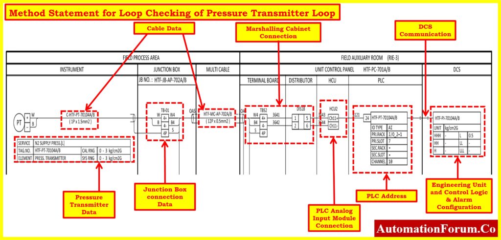
1.Installation Verification:
- Ensure that the installation is completed as per the installation drawing provided.
- Verify the installation against the hookup drawing and bench calibration report to ensure accuracy.
2.Loop Integrity Check:
- Inspect the entire loop, including the transmitter, connecting cables, and any junction boxes, for any signs of damage or degradation.
- Check all connections for tightness and security to prevent any potential leaks or electrical faults.
- Ensure that there are no short circuits or open circuits in the loop by conducting continuity tests using the multimeter.
3.Check Relevant Datasheet for Transmitter Ranges:
- Review the relevant datasheet for the pressure transmitter to confirm the specified ranges and operating parameters.
4.Confirmation with ILD and P&ID Verification:
- Confirm with the Instrumentation and Loop Diagram (ILD) team that the loop is complete and verified.
- Verify proper tagging and installation according to the Process and Instrumentation Diagram (P&ID).
5.Cable Termination and Continuity Check:
- Verify cable termination as per the interconnection drawing and review cable megger reports.
- Execute a continuity check to ensure proper electrical connections throughout the loop.
6.Power Up:
- Begin by ensuring that the power supply to the pressure transmitter loop is switched off to prevent any electrical hazards.
- Connect the multimeter across the loop terminals to measure the voltage.
- Switch on the power supply and verify that the transmitter receives power. Measure the voltage across the loop terminals to ensure proper power supply and electrical continuity.
- Verify the transmitter display during initial start-up to ensure proper functioning.
- Allow 2 to 3 minutes of warm-up time for the instruments to stabilize.
7.PLC/DCS Configuration and Tag Verification:
- Check and verify the PLC/DCS control system configuration for applicable points.
- Power on the circuit and verify the Transmitter Tag No. and range using a HART communicator.
8.Signal Generation(Loop simulation):
- Connect the signal generator to the input terminals of the pressure transmitter.
- Generate a simulated pressure signal using the signal generator(Loop calibrator) to simulate actual operating conditions.
- Observe the output signal from the pressure transmitter and ensure it corresponds to the input signal from the signal generator(Loop calibrator). This step verifies the accuracy and linearity of the transmitter’s response to applied pressure.
- For smart transmitters, the case (HART) communicator shall be utilized for simulation purposes instead of the hand pump and loop calibrator.
- For Foundation Field bus case (FF), communicator shall be utilized for simulation purposes instead of hand pump and loop calibrator.
9.Field Calibration:
- Perform calibration of the pressure transmitter using calibration equipment to ensure accurate measurement readings.
- Adjust the transmitter’s settings as per calibration standards to ensure the output signal corresponds accurately to the applied pressure levels.
10.Functional Testing:
- Apply varying pressure levels (0, 25, 50, 75, and 100% of the instrument range) to the pressure transmitter using the pressure calibrator and observe its response.
- Verify the transmitter response at the PLC/DCS.
- Verify that the output signal from the transmitter accurately reflects the applied pressure levels within the specified range.
- Test the response time of the transmitter to changes in pressure to ensure its dynamic performance meets the required standards.
11.Instrument Response and Engineering Units Check:
- Verify the response of the instruments as per the calibration certificate.
- Confirm the corresponding readings in the PLC/DCS and remote indicators if applicable.
- Check the display for proper engineering units.
12.Alarms and Trip Function Verification:
- Verify all associated alarm and trip functions by simulating various transmitter outputs and adjusting trip limits accordingly.
14.Verify Loop Completion and Internal Test Report:
- Ensure that all steps are documented in the internal test report for future reference and auditing purposes.
Step 5: Post-Testing Steps:
After completing the loop checking procedure, several post-testing steps need to be undertaken to document the results and address any issues identified during testing:
- Record all test results and observations accurately to maintain a comprehensive record of the loop checking process.
- If any issues are identified during testing, troubleshoot and rectify them promptly to ensure the proper functioning of the pressure transmitter loop.
- Perform any necessary adjustments or calibration to ensure the accuracy and reliability of the pressure transmitter’s measurements.
- Document the completion of loop checking and any actions taken, including calibration adjustments and repairs, for future reference and audit purposes.
- Confirm that the loop checking process is completed and witnessed according to internal test report procedures.
Step 6: Completion of Loop Checking
- Conduct a final inspection of the pressure transmitter loop and associated equipment to ensure that all components are in proper working condition and that there are no visible signs of damage or defects.
- Ensure that all tools and equipment used during the loop checking procedure are properly cleaned, stored, and secured to prevent loss or damage.
- Dispose of any waste materials or debris generated during the testing process in accordance with established waste management procedures and regulations.
- Review the internal test report to ensure that all required information, including test results, observations, and any corrective actions taken, are accurately documented.
- If applicable, obtain necessary approvals or signatures from authorized personnel to confirm the completion of the loop checking process and the acceptance of the pressure transmitter loop.
- Provide appropriate feedback or recommendations based on the findings of the loop checking procedure to improve future installations or maintenance practices.
- Archive the internal test report and any relevant documentation in a secure location for future reference, auditing, or compliance purposes.
Loop Check Report Template for Pressure Transmitter – Downloadable
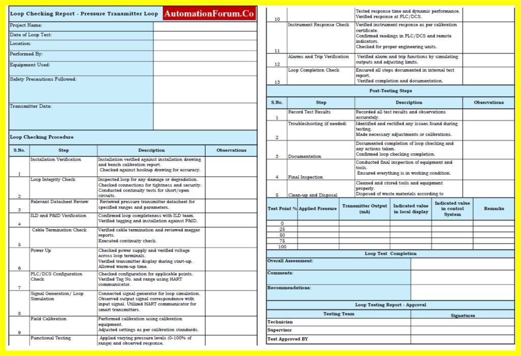
Please follow the link below to access the downloadable Loop Check Report Template for Instrumentation Project Engineers.