Table of Contents
- What is an instrumentation cable?
- What are the types of network cables used in communication system?
- What are the Different Types of Cables used in Instrumentation?
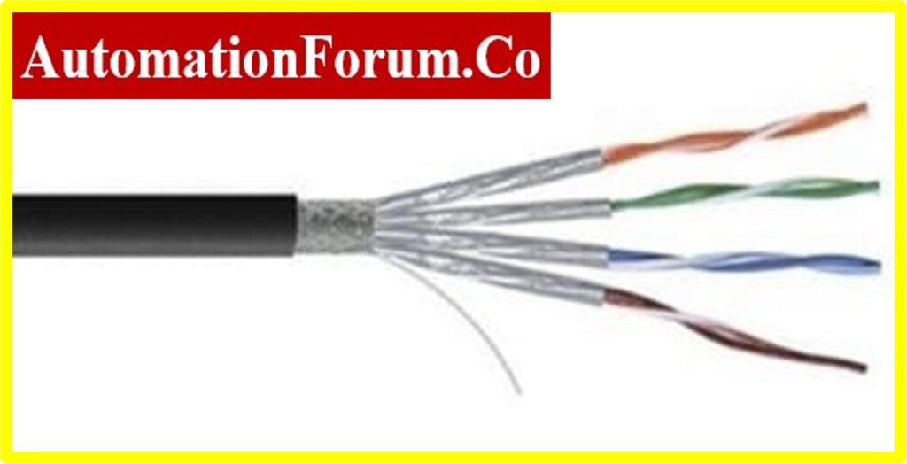
- Shielded Twisted Pair (STP) Cable:
- Unshielded Twisted Pair (UTP) Cable:
- Coaxial Cable:
- Advantages of Coaxial Cable :
- Dis-advantages of Coaxial Cable :
- Optical Fiber Cable:
- Advantages of Optical Fiber Cable:
- Dis-Advantages of Optical Fiber Cable:
- Fieldbus Cable:
- Profibus Cable:
- Difference between Profibus PA and Profibus DP :
- How many devices can connect in PROFIBUS?
- What is the maximum length of PROFIBUS cable per segment?
- Thermocouple Compensating Cable:
- Why are compensation used with thermocouples?
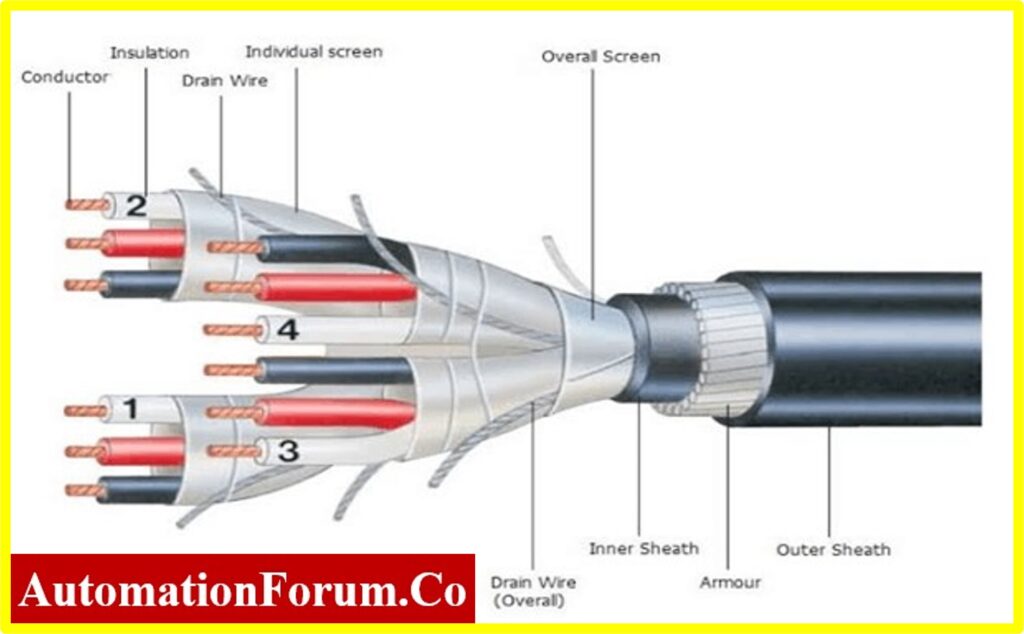
What is an instrumentation cable?
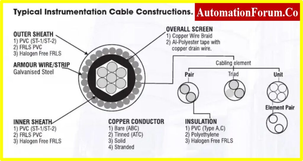
- Instrumentation cables are single-pair or multi-pair cable elements designed to convey electrical signals from one point to another.
- These cables are suitable in harsh environments with outstanding electrical, physical, and thermal features.
- These instrumentation cables are used in all process industries and power plants for connecting various field instruments and electrical equipment in a control system.
- The signals generated through various transducers are transmitted to panels, electronic or PID controllers, and field instruments.
- Generally, based on the signal level these instrumentation cables are classified into three main types
- Instrumentation High-level signals: The signal level in these cables lies between 1V to 50V.
- Instrumentation Low-level signals: The signal level in these cables lies below 6V.
- Instrumentation Power Supply: The signal level in these cables lies above 50V.
What are the types of network cables used in communication system?
- Cable types used for a network depend on the network topology used, Size, and Procedure.
- Twisted pairs, coaxial cables, and optical Fiber cables are considered as three major types of network cables in communication system.
- The network cable connects one network device to one or more network devices or to a single computer.
- Network cable functions as a channel to communicate data and information between various network devices.
What are the Different Types of Cables used in Instrumentation?
To convey electric signals from one point to another, there are various types of cables used in instrumentation.
Shielded Twisted Pair (STP) Cable:
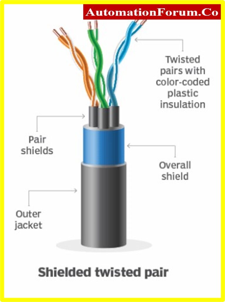
- The Shielded Twisted Pair (STP) cable in general is referred to as simply Ethernet cable.
- These Shielded Twisted Pair cable consists of a special type of copper telephone cabling used in business installations.
- An external shield functions as a ground combined with the standard twisted pair of telephone wires.
- These Shielded Twisted Pair cables are best suited in areas or locations having high risks and potential interference.
- This Shielded twisted pair cable helps in expanding the cable distance.
- This Shielded twisted pair cable includes four pairs of signal-carrying wires acts as a conducting shield to reduce the cause of electromagnetic interference.
- STP cables are categorized as CAT-5, CAT-6, CAT-6a, and CAT-7.
STP cables are further classified as
A. Foil Twisted Pair (FTP):
These FTP cables are lighter & foil shields. During installation bend radius, and pulling tension must be carefully monitored to prevent tearing.
B. Shielded Foil Twisted Pair (SFTP):
SFTP is another type of STP cabling system that uses thick weaved shield to make the cable sturdier to avoid the possibility of tearing.
These cables are twisted and shielded to deliver maximum protection against cross-talk and electromagnetic interference.
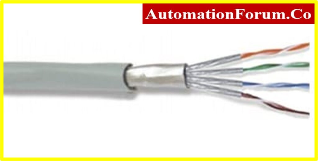
Unshielded Twisted Pair (UTP) Cable:
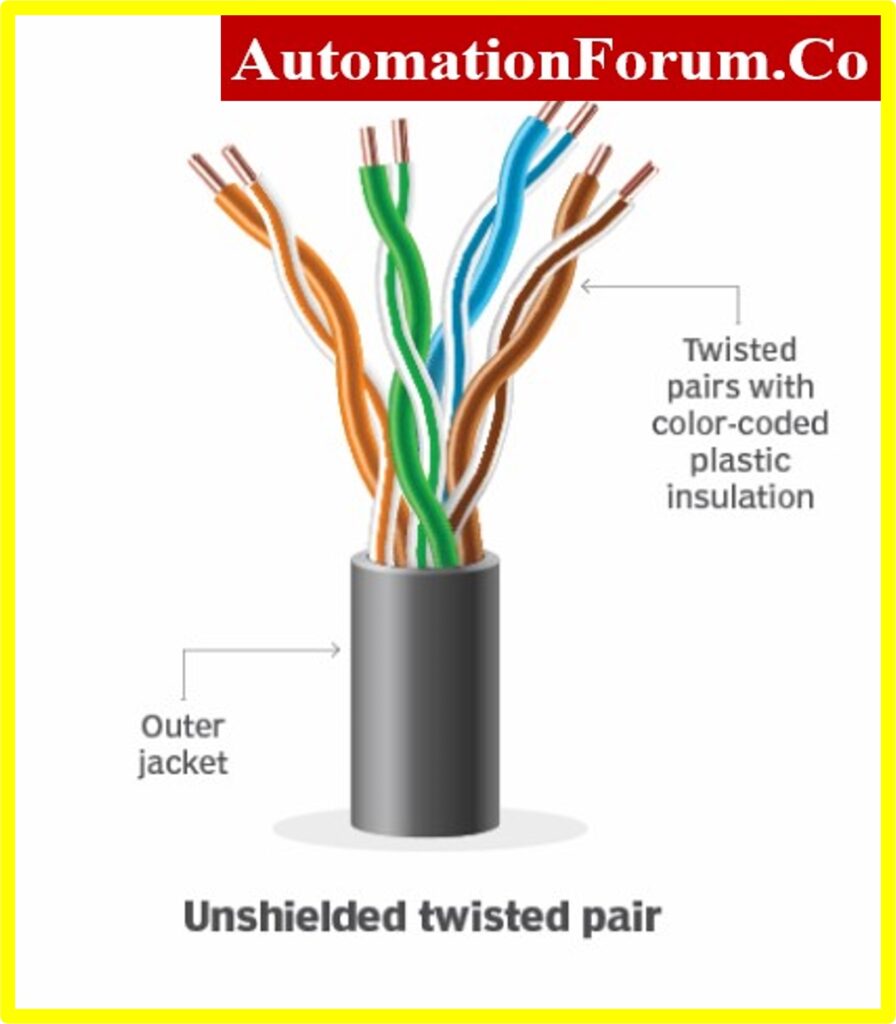
- The Resistance of the UTP copper cable is 100 ohms.
- This cable contains about 2 to 1800 unshielded twisted pairs enclosed by an outer jacket.
- These cables do not have any kind of metallic shield.
- This cable doesn’t provide any protection against electrical interference.
- The twisted pair improves immunity to electrical noise and electromagnetic interference.
- UTP cables are categorized as CAT-5e and CAT-6.
- For horizontal cables, the number of pairs is four (4). But for backbone cables, the number of pairs is incremented to 25.
- Copper conductor size for both horizontal and backbone UTP cable is AWG-22, or AWG-24. But, AWG-24 is considered as most common size.
- CAT-6 is a higher-performance cable that uses AWG-24 copper wire.
- UTP cables were developed for voice applications to convey analog signals.
- These cables are tough and are not damaged by electrical noise or electromagnetic interference.
- These Unshielded twisted pair (UTP) cables are widely used in Telecommunication, Computer, and Networking sectors as Ethernet cables.
- UTP cables are categorized as
- Higher-category UTP – Cables are acclaimed as Data grade UTP cables.
- Lower-category UTP – Cables are acclaimed as Voice-grade UTP cables.
Coaxial Cable:
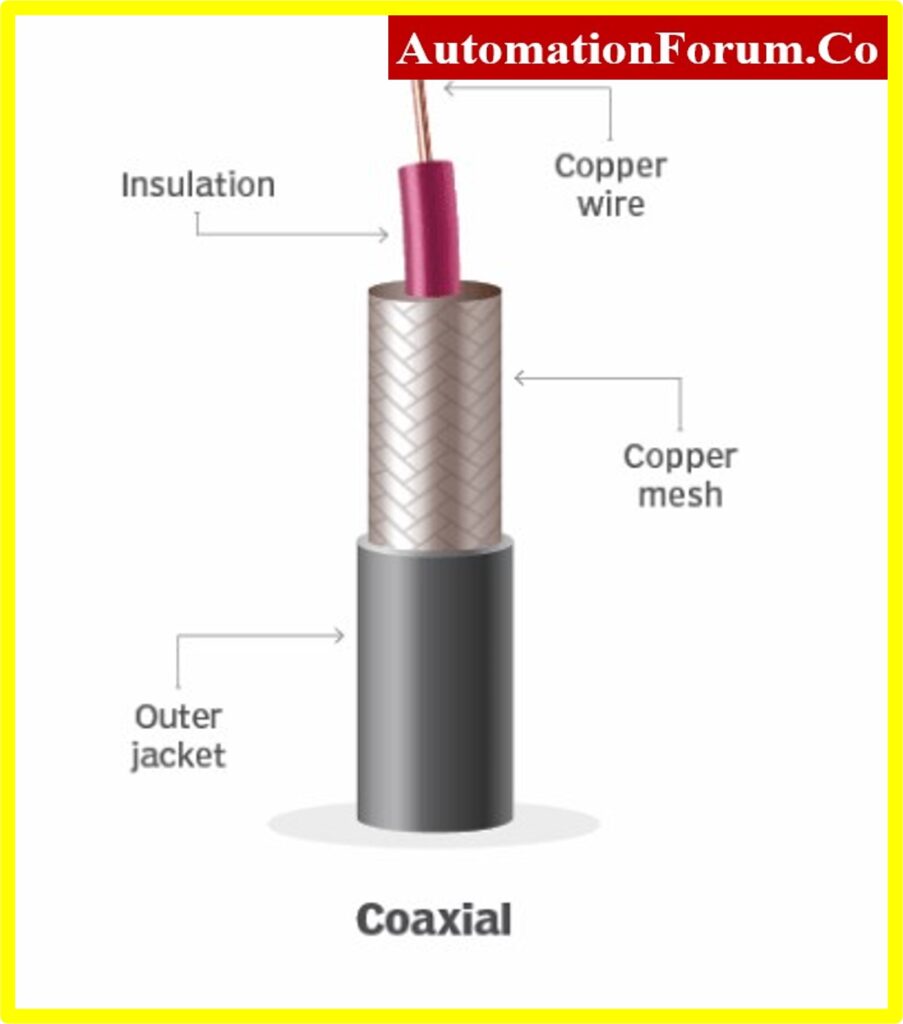
- The coaxial cable is composed of two conductors, an outer braided cylinder, and an inner stranded conductor.
- The solid dielectric material lies between the inner conductor and the outer cylinder.
- The term coaxial refers to the inner conductor and the outer cylinder shield sharing a geometrical axis.
- The outer cylinder is enveloped by an insulating jacket for overall protection.
- The application of coaxial cables consists of feed lines to connect radio transmitters and receivers to their antennas.
- In an ideal coaxial cable, the electromagnetic field that carries a signal survives in the space between the inner conductor and outer cylinder.
- A coaxial cable is a flexible transmission medium to convey a large amount of data.
- These cables are used in point-to-point or multipoint configurations.
- These cables are commonly found in bus network topology, and in a ring topology (Rare case).
- Coaxial cabling is used for both analog signalling and digital signalling referred to as broadband.
Advantages of Coaxial Cable :
- Protects the signal from external electromagnetic interference.
- Reduces power losses.
- It has better noise immunity than twisted pair.
- It is cheaper than Fiber Optic Cable.
Dis-advantages of Coaxial Cable :
- Coaxial cable is costlier than twisted pair cable
- During the installation period, these coaxial cables must be carefully handled.
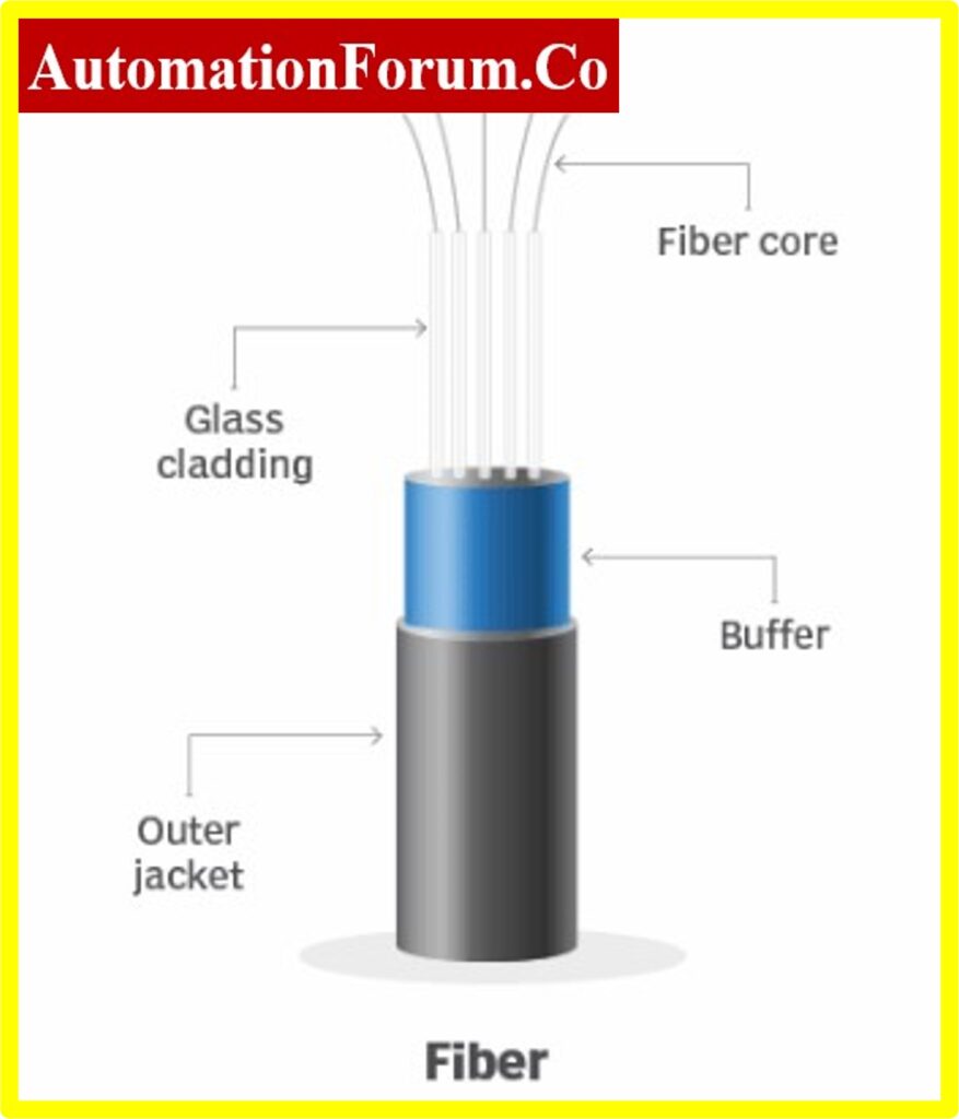
Optical Fiber Cable:
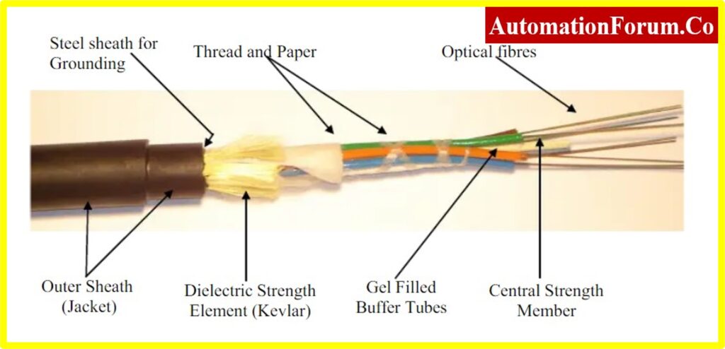

- Optical Fiber communication system is surfaced as the most significant communication system.
- An Optical Fiber cable comprises of a glass core or plastic core, and cladding as the outer protective jacket.
- The optical Fiber sends a modulated light wave through Internal Reflection.
- Light wave from a laser or LED source is allowed to enter the cylindrical core for propagation.
- This propagated light wave is now de-modulated into a corresponding electronic signal.
- The laser light source is more efficient and gives higher bandwidth.
- This LED functions at a higher temperature range.
- Fiber optic is commonly employed in point-to-point links such that these light signals can communicate over long distances.
- Fiber optic cable is unsusceptible to electrical interface, and ground loops since no electrical signals are transmitted into it.
- It can be safely routed through dangerous and explosive environments.
- Optical Fiber cables are non-conductors of electricity hence magnetic field is not generated.
- There are no shock hazards because the current or voltage source is not associated with these cables.
- Fiber optic cables give less signal attenuation, less than 1 dB/km it enabling long-distance communication between repeaters.
- This light wave occupies the frequency range of about 2*1012 Hz to 3.7*1012 Hz.
- Optical Fiber cable has a higher information-carrying capability.
- Optical Fiber cable has a smaller diameter compared to other cables and therefore requires very less storage space.
- Fiber cables are not affected by corrosive liquids and gases.
Advantages of Optical Fiber Cable:
- Installation and maintenance of optical Fiber cables are easy and safe.
- Fiber cables are stronger and more rugged hence supporting more weight.
Dis-Advantages of Optical Fiber Cable:
- Optical Fiber links are more expensive than twisted pairs or coaxial cables.
- The Fiber joining process costs more, and requires skilled labour, because of small size.
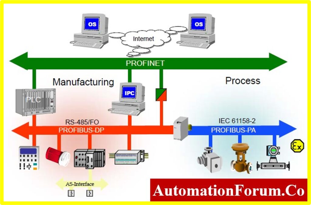
Fieldbus Cable:

- Fieldbus is a group of communication protocols used in industrial process control systems.
- These Fieldbus communication protocols have been standardized as IEC61158.
- Generally, Fieldbus works on a network system that enables various network topologies such as the bus, ring, branch, star, and daisy chain topologies.
- Prior to Fieldbus protocols, RS-232 serial communications are used to connect various control systems that enables only two devices to communicate with each other.
- The Field bus enables connection for multiple field devices into a single connection point or node that would further link to the controller.
- The connection schematic of Fieldbus depends upon the Fieldbus protocol used.
- There are several protocols such as Control Net used in the Allen Bradley family, Modbus, Profibus, Ether CAT, HART, CIP, and so on.
- Fieldbus device connection saves the cost of wiring runs made to the controller.
- The controller system must have a communications module with the ability to establish communications within these field devices.
- Control-Net requires a Control-Net module, whereas Profibus requires a Profibus module.
- These Fieldbus devices are connected to a Programmable Logic Controller via a field distribution device and I/O data block.
- The trunk cable must be a maximum of 8 pairs overall and individually screened cable.
- Each Foundational Field device must be connected to the Fieldbus JBs through a single-pair screened spur cable.
- Intermediate JB contains pass-through terminal blocks to connect a maximum of 8 H-1 segment to the trunk cable.
- Only Tree, Spur, and a combination of tree and spur topologies are used.
- Standard Cable Characteristics as per IEC Physical Layer.
| Wire Size | 18 AWG or 0.8 mm² |
| Shield | 90% coverage |
| Maximum Attenuation | 3 dB/km at 39 kHz |
| Maximum Capacitance | 150 pF/m |
| Characteristic Impedance | 100 Ohms +/- 20% at 31.25 kHz |
| Maximum DC Resistance | 24 ohms/km (per conductor) |
- All trunk cables and spur cables must follow Instrument Cabling IEC- 61158-2 specification.
- Fieldbus Cable Length is limited to a maximum of 1900 meters.
- The net segment length is calculated by combining the length of the main trunk line and all the spurs.
Net Segment Length = Main Trunk + All Spurs
- Generally, segment length is limited by voltage drop and signal quality such as attenuation and distortion.
- The following limits are used to reduce validation requirements and need to calculate the physical loading of each segments
- Trunk cable length ? 800 meters
- Spur cable length ?75 meters
- Power Consumption: Maximum segment current is limited to 350 mA.
- Foundation™ Fieldbus operates at a frequency of 31.25 kHz.
- An attenuation of standard field bus cable is 3 dB/km at 39 kHz or about 70% of the original signal after a distance of 1 km.
- Fieldbus cable rates according to four-level codes such as A, B, C, or D.
- Each successive letter represents unique cable quality.
- Specifications of various Fieldbus cables are shown in below table.
| Cable Type | Type A | Type B | Type C | Type D |
|---|---|---|---|---|
| Wire Size | AWG 18 | AWG 22 | AWG 26 | AWG 16 |
| Impedance | 100 ohms + 20% | 100 ohms + 30% | – | – |
| Shielding | 1 for each Pair | 1 for entire cable | – | – |
| Twisted Pairs | Yes | |||
| Max. Length | 1900 m | 1200 m | 400 m | 200 m |
Profibus Cable:
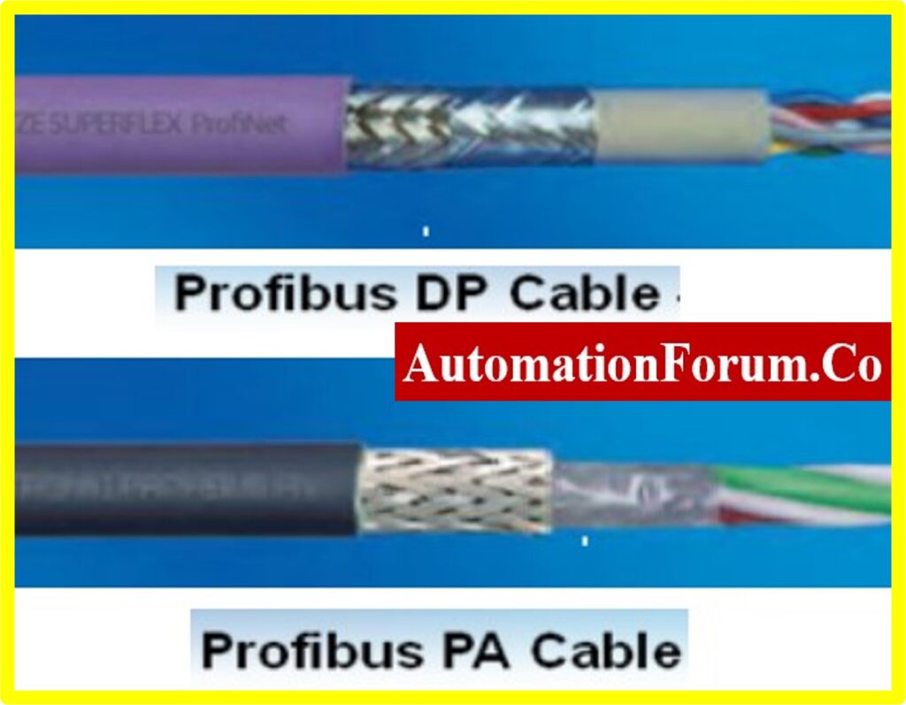
- In an industrial automation system, A Profibus is a digital communication protocol that can be done over a two-wire system.
- Profibus cables are developed for particular process automation cabling applications for industrial fast-connect type systems.
- Profibus DP and Profibus PA are two variants of Profibus.
- Profibus provides excellent electrical transmission performance for Decentralised Peripherals (DP) and Process Automation (PA) applications.
- The Profibus DP is a widely used variant and is considered the standard PROFIBUS by many experts.
- These Profibus communication protocols have been standardized as IEC-61158.
- Especially, these cables are designed to deliver time-critical communication between process automation systems and distributed peripherals.
- Profibus is essentially a data communication system allowing for a large number of devices to share a two-core copper cable bus system.
- They are widely used in factory processes, and in-field communications in cellular networks.
- Profibus DP is configured as master. Because the master actions slave continuously by sending device outputs with a command and accepting the inputs back.
- They provide data transmission speed at a range of 9.6 kbps to12 Mbps.
- The maximum length of Profibus DP cables may be up to 1000 meters long. But, too achieve higher data rates short cable length is recommended.
Difference between Profibus PA and Profibus DP :
| Type | PROFIBUS PA | PROFIBUS DP |
|---|---|---|
| Purpose | Explosion safety (Ex) | Fast |
| Technology | MBP-IS | RS-485 |
| Baud-Rate | 31.25kbps only | Up to 12Mbps |
| Cable | Shielded twisted pair. | Shielded twisted pair. |
| Restriction | Data and Power supply | Data only |
| Cable length | Up to 1900m | Up to 1200m. |
| Topology | Bus, star, tree | Bus |
How many devices can connect in PROFIBUS?
- Profibus accommodates up to 32 devices per segment,
- Depending upon the system current, Profibus can support up to a total of 126 masters and devices on a single PROFIBUS network.
What is the maximum length of PROFIBUS cable per segment?
- The maximum length of PROFIBUS cable per segment established is up to 1200 meters at 9.6 kbps.
- Compared to conventional non-digital systems, Profibus saves cabling and installation costs.
Thermocouple Compensating Cable:
- Temperature measurement is an important factor in many areas concerning environmental conditions.
- Temperature is a thermodynamic variable that defines the heat content of a body.
- Material strength varies with consecutive temperatures.
- Thermocouple compensating cable is a type of cable that uses a different composition to extend the cable.
- This cable extends a thermocouple signal from the sensor to the instrumentation
- These compensating cables and strands are composed of certain metal alloys which are not identical to the corresponding thermocouple.
- These cables are cheaper than extension cable.
- These cables have a similar temperature versus EMF relationship over a specified range.
- These extension cables include thermocouple elements to manufacture thermocouples.
- The accuracy of these compensating cables is lesser than extension cables.
- These cables can only be used in ambient temperatures.
- Compared to an extension cable, this cable is much cheaper and economical to run in instrumentation systems.
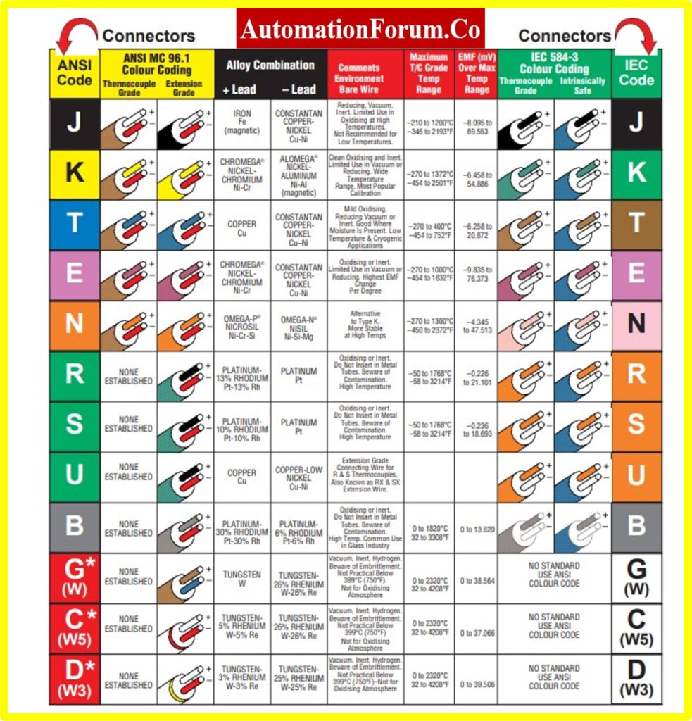
- Common types of thermocouple compensating cables such as
- Type Vx/KCB (for Type K thermocouples)
- Type U (for Type R and S thermocouples).
Letter “X” adapted to DIN IEC 584
- Compensating cables are insulated with poly Vinyl Chloride, though the operating temperature lies within PVC’s physical limits.
- Customized Compensating Cables & Thermocouple Extension Cables
- According to international standards, special thermocouple compensating cables has the following information:
- Stranded or solid conductor
- Number of cores
- Cross-section area
- Type of element
- Core insulation
- Sheath material.
- Screening or Armour requirements
- Temperature range
Why are compensation used with thermocouples?
- Cold junction compensation remunerates for missing thermoelectric voltage because the thermocouple cold end at the instrument is not at (0°C /32°F).
- So electronics are used to establish thermoelectric voltage tables to determine the temperature at the hot end.