- Role of HART Communication in Industrial Automation
- Essential Purposes of the 250-Ohm Resistor in HART Communication
- What is the purpose of a 250 Ohm resistor?
- Practical Considerations for Implementing the 250-Ohm Resistor
- Broader Impact of the 250-Ohm Resistor
- Why do we use a 250 Ohm resistor in 4 to 20mA?
- Resistance Value in HART Protocol
- HART Loop Resistor Location in the instrument loop
- HART Loop Resistor Location on the Bench calibration
- Why Don’t I need a HART Loop Resistor on Some Loops?
- Future of HART Communication
- Test Your HART Protocol Knowledge
- How much resistance must be present in a loop for HART communication to work?
- What is a HART resistor?
- Why is a 250-ohm resistor used in HART communication?
- What is the purpose of a HART communicator?
Effective communication between devices is critical in industrial automation to ensure efficiency, accuracy, and reliability. Among the different communication protocols available, HART (Highway Addressable Remote Transducer) is a flexible and extensively used standard.
Analog and digital technologies can be connected using HART communication, which enables digital data and a 4–20 mA analog signal to be transmitted over the same pair of wires. The 250-ohm resistor is a critical component in this process, as it ensures good signal transmission and system functioning.
This article discusses the 250-ohm resistor’s critical functions in HART communication, including signal conversion, signal integrity, compliance with industry standards, and system integration.
Role of HART Communication in Industrial Automation

HART communication is intended to improve typical 4-20mA analog signaling by superimposing digital information over the same channel. This hybrid technique has various advantages, including the ability to convey accurate diagnostic and configuration data while maintaining the primary process control signal. HART facilitates two-way communication and real-time monitoring, which increases process efficiency and reduces downtime.
In order to attain these advantages, specific elements and design factors need to be incorporated into the HART network, of which the 250-ohm resistor is essential.
Let us explore why this resistor is so important to HART communication.
Essential Purposes of the 250-Ohm Resistor in HART Communication
What is the purpose of a 250 Ohm resistor?
Signal Conversion for Accuracy
- One of the key functions of the 250-ohm resistor in a HART communication system is to assist signal conversion. HART devices communicate over a 4-20mA current loop.
- To allow for correct data transfer and interpretation, the 250-ohm resistor turns this current into a comparable voltage signal.
- This conversion follows Ohm’s Law, in which the voltage (V) is equal to the current (I) multiplied by the resistance (R):
- The voltage produced by running a current of 4-20mA through a 250-ohm resistor ranges from 1 to 5 volts.
- This voltage range is precisely suited to the input needs of most HART communicators and control systems, assuring compatibility and accurate signal processing.
- In the absence of this resistor, the system would not have a dependable way to transform the analog current into a measured voltage, which could result in signal errors and poor system functionality.
Refer the below link for the How a PLC reads the data from field transmitters?
Maintaining Signal Integrity
- In every communication system, maintaining the integrity of the transmitted signal is critical. The 250-ohm resistor is critical to maintaining the right impedance load in the HART network.
- The resistor stabilizes the current loop by supplying the appropriate impedance, reducing the risk of signal distortion or degradation.
- Frequency Shift Keying (FSK) is used in HART communication to encode digital data onto an analog current loop.
- The stability provided by the 250-ohm resistor ensures that the overlaid FSK signal is clearly conveyed, avoiding errors, data loss, or miscommunication. For accurate industrial process monitoring and control, this stability is required.
Compliance with HART Standards
- The HART Communication Foundation (now part of the FieldComm Group) develops standards to promote interoperability and reliability among devices and systems.
- Among these standards, the use of a 250-ohm resistor is specifically suggested to ensure HART network consistency and compatibility.
- By following to this standard, manufacturers and system integrators can ensure that their devices work properly in any HART-enabled system.
- The resistor guarantees that communication between analog and digital systems is seamless, dependable, and meets industry standards.
- This standardization is especially useful in large-scale manufacturing environments where many devices from multiple manufacturers must work together.
Simplified Integration
- Another significant benefit of employing a 250-ohm resistor is that it simplifies the integration of HART communication into existing systems.
- The resistor reduces the need for expensive signal conditioning equipment by allowing for voltage conversion and impedance stability.
- This simplification decreases the complexity of system design, speeds up installation, and cuts total costs.
- Engineers may simply insert the resistor into the loop while maintaining performance, making it an efficient and cost-effective alternative for industrial automation projects.
Practical Considerations for Implementing the 250-Ohm Resistor
Even though the 250-ohm resistor has several advantages, using it correctly is essential to maximizing its efficiency.
For your consideration, the following are some helpful points to keep in mind:
- Placement: The resistor should be connected in series with the current loop, often near the HART communicator or control system’s input terminals.
- To achieve accurate voltage conversion and signal stability, utilize high-quality resistors with low tolerance levels (±1% or better).
- Environmental Considerations: In industrial settings, the resistor may be subjected to temperature fluctuations, dampness, and other severe circumstances. Reliable operation requires resistors with acceptable temperature and durability ratings.
Broader Impact of the 250-Ohm Resistor
In addition to its technical uses, the 250-ohm resistor’s contribution to HART communication advances the larger objectives of industrial automation. The resistor facilitates better process management, better decision-making, and lower operating costs by facilitating dependable and efficient data sharing. Because of its ease of use and efficiency, it is a fundamental component of HART-enabled systems, enabling companies to attain greater performance and production levels.
Why do we use a 250 Ohm resistor in 4 to 20mA?
The use of a 250 Ohm resistor in 4-20 mA current loops is primarily to convert the current signal into a proportional voltage signal for measurement or control purposes. Here’s a breakdown of why it is used and how it works:
Voltage Conversion for Readability
In many control systems, devices such as Programmable Logic Controllers (PLCs) or analog-to-digital converters (ADCs) operate with voltage inputs.
To monitor the 4-20 mA current loop, the resistor generates a measurable voltage across its terminals.
Proportional Voltage Range
A 250 Ohm resistor is chosen because it creates a convenient and linear voltage range:
- At 4 mA: V = I x R = 4×10?3 x 250 = 1?V
- At 20 mA: V = 20 ×10?3 x 250 = 5?V
This 1-5 V range is easy for most analog devices to handle and interpret.
Standardization
The 250 Ohm resistor ensures compatibility with industry-standard equipment, which is often designed to work with 1-5 V signals derived from 4-20 mA loops.
Power Dissipation
The power dissipated in the resistor (P=I2xR) is low enough to avoid overheating, while still providing a useful voltage range.
Refer the below link for the Why 4-20 mA Current Signal is Preferred Over Voltage Signal in Instrumentation?
Resistance Value in HART Protocol
According to the HART specification, the Loop Resistor value should be between 230 and 600 ohms. Typically, 250 ohms are utilized. This value allows for a simple conversion from a current value to a voltage value, which is employed in some control systems. For instance, 4mA through a 250-ohm resistor corresponds to 1Vdc, and 20mA corresponds to 5Vdc.
HART Loop Resistor Location in the instrument loop
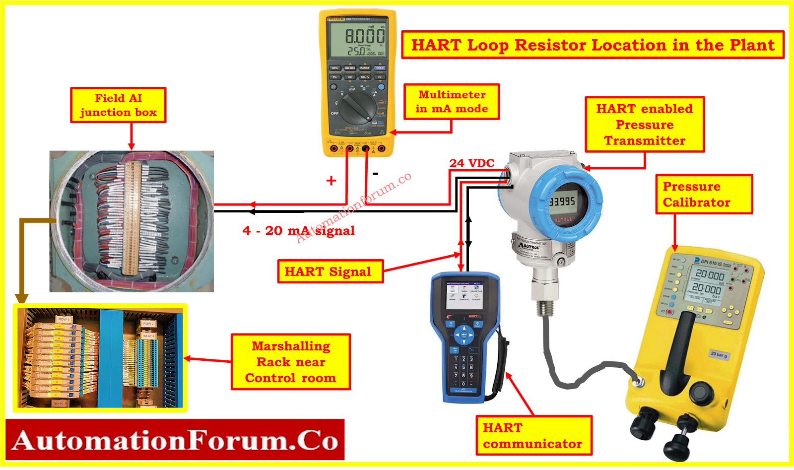
Where should the resistor be placed?
The answer depends on the specific setup. It can be installed anywhere in series within the loop.
- PLC I/O Card: A convenient location is within the PLC I/O card itself. For example, the Allen-Bradley model 1756-IF8 I/O card includes a built-in loop resistor.
- Marshaling Cabinet: If the PLC lacks a built-in resistor, the resistor can be placed in the marshaling cabinet. The resistor may be easily inserted into this cabinet, which is frequently situated between the control room and the plant floor.
- HART Instrument: The least desirable alternative is to place the resistor on the HART instrument itself, as this requires interrupting the loop. However, if necessary, a resistor can be connected directly at the instrument’s loop connection. Ensure the instrument enclosure can accommodate the resistor and be refastened properly.
HART Loop Resistor Location on the Bench calibration
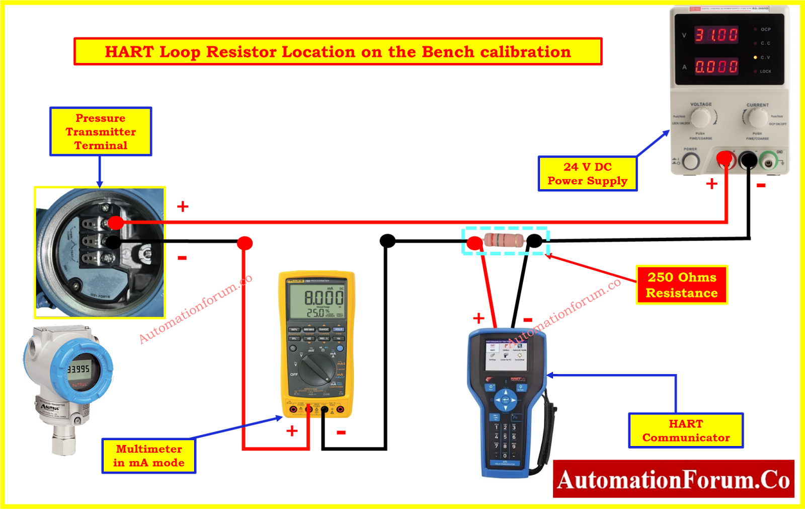
In laboratory settings, there are more flexible options for resistor placement:
- Direct Connection: Connect a resistor to one of the instrument’s loop connections, then connect the power supply to the other end of the resistor.
- A built-in resistor function may be present in a loop calibrator, if one is accessible. For example, users can activate the loop resistor directly on the calibrator with the Fluke 789.
- ModernHART Modems: Bench testing is made easier by some current HART modems that have an integrated loop resistor and can power the instrument.
Click here for Wiring Diagram for Pressure Transmitter Calibration in Workbench using HART
Why Don’t I need a HART Loop Resistor on Some Loops?
Some loops may already have adequate resistance because of long cable runs, even though the loop resistor is a requirement of the HART specification. In these cases, the natural resistance of the wiring may fulfill the requirement, especially if the HART modem’s output and sensitivity exceed the standard specifications. However, there is a greater chance of noise interference when utilizing modems with more sensitive inputs, which may affect the reliability of communication.
Click here for HART transmitter calibration procedure
Future of HART Communication
There will always be a loop resistor needed for HART. The physical layer stays consistent with FSK (Frequency Shift Keying, or normal HART) despite innovation like PSK (Phased Shift Keying, or High-Speed HART). As a result, the loop resistor will remain an essential part of HART systems.
Test Your HART Protocol Knowledge
Take this Advanced HART Protocol Quiz with 25 multiple-choice questions and detailed explanations. Perfect for enhancing your skills or preparing for interviews.
Start the Quiz Now with below link
FAQ on HART Communication and Resistors
How do you connect a resistor for a HART communicator?
To connect a 250-ohm resistor for HART communication:
- Insert the resistor in series between the device terminals.
- Connect the lead set of your HART communicator across the resistor.
Alternatively, some HART communicators allow you to enable an internal resistor through their device connection wizard. Always refer to the device documentation for specific setup instructions.
How much resistance must be present in a loop for HART communication to work?
The minimal loop resistance needed for HART communication is 230 ohms. This resistance is crucial to create the necessary impedance for the communication signal to function effectively.
What is a HART resistor?
A HART resistor, as defined by the HART FSK Physical Layer Specification (HCF_SPEC-054), is essential for enabling HART communication. It serves two primary purposes:
- Converts the current-based HART signal into a voltage signal.
- Prevents the loop power supply from canceling out the HART signal, ensuring reliable communication.
Why is a 250-ohm resistor used in HART communication?
The HART specification recommends a loop resistor value between 230 ohms and 600 ohms. A 250-ohm resistor is commonly used because it provides:
- Easy conversion of current to voltage (4mA equals 1V, and 20mA equals 5V).
- Compatibility with standard control systems designed for these voltage ranges.
What is the purpose of a HART communicator?
A HART communicator is a portable device that used to:
- Commission, calibrate, and troubleshoot process instruments.
- Communicate with and check the status of field devices using the HART protocol.
- Manage and organize smart field devices efficiently from remote locations.