Table of Contents
What is a HART transmitter?

- Highway Addressable Remote Transducer is what the letters “HART” stand for in the acronym.
- On top of the 4-20mA, the HART Protocol will superimpose low-level digital communication signals using the Frequency Shift Keying (FSK) standard.
- This will keep the degree of interference to a minimum. This enables two-way field communication to take place and makes it possible for additional information beyond just the normal process variable to be communicated to or from a smart field instrument.
- Additionally, this makes it possible for additional information to be communicated to/from a smart field instrument.
- A host application, also known as a master, is able to receive two or more digital updates per second from a smart field device by using the HART Protocol, which communicates at a rate of 1200 bps and does so without disrupting the 4-20mA signal.
- There is no interference with the 4-20mA signal since the digital FSK signal has a phase that is continuously present.
- Both an analogue signal with a range of 4-20 mA and a digital signal are made available to users via the HART Protocol, which allows for simultaneous use of both.
- The principal measured value (in the case of a field instrument) is communicated with the help of the 4-20mA signal by using the 4-20mA current loop, which is the quickest and most reliable industry standard.
- A digital signal is overlaid on the analogue transmission in order to facilitate the communication of more information regarding the device.
- Information may only travel in one direction when using an analogue signal, and that direction can be either from the device to the host (inputs) or from the host to the device (outputs).
- The HART digital communications signal, on the other hand, enables information to go in either direction, making digital data more versatile.
- This opens the door for an instrument such as a valve controller, which in the past could only receive control-signal information from a host, to now also transmit information to the host about what is occurring at the valve.
- In a similar manner, a transmitter that, in the past, was only able to send a process variable to the host may now also receive information such as configuration settings.
How do you calibrate a HART pressure transmitter?
Purpose and Scope:
The detailed description of this process explains how to calibrate HART pressure transmitter using standards in the process area.
Tools required for HART pressure transmitter calibration:

- Necessary hand tools.
- Standard Pressure Calibrator.
- Standard Multimeter.
- Test leads and probes.
- Tubes and standard fittings
- Soft Cloth for cleaning.
- HART communicator
Safety
- Please visit the linked link to learn more about fundamental safety, general suggestions, and calibrating operations in process industries.
Process Industry Calibration Process: Basic Safety and General Aspects
- Request that the SCADA/DCS panel operator set the controller in manual mode for the control loop of the pressure transmitter and MOS for the ESD loop.
- Find the pressure transmitter that you wish to calibrate. Verify the pressure transmitter is the appropriate one and note any important details, such as the Tag number (e.g., the manufacturer, model number, pressure range, etc.).
- Before removing the pressure transmitter, be sure there is no pressure or fluid flowing through the instrument by stopping the operation.
- Close or disconnect the pipe that connects the pressure transmitter to the process. No fluid will leak out as a result of the pressure transmitter being isolated from the process.
- Any pressure that could have been held inside the pressure transmitter can be released by opening the bleed or vent valves on the pressure transmitter.
- Once the HART pressure transmitter has been disconnected, consult the transmitter nameplate for the relevant info.
- Keep in mind that based on the particular equipment and process location, this basic procedure may need to be altered. While working with HART pressure transmitters or any other process equipment, always adhere to any manufacturer’s recommendations as well as local safety standards.
- To avoid an unintended start, adhere to all applicable lockout/tagout protocols. Make sure the HART transmitter is kept separate from the operation.
Calibration Setup

- The placement of the calibration equipment must be free from vibrations and electromagnetic interference. Also, the space has to be well-ventilated and lighted.
- Get all of the instruments and resources that are required.
- The pressure calibrator’s output should be attached to one end of the tube, and the pressure port side of the HART pressure transmitter should be connected to the other end. Check the connections to ensure they are tight and leak-free.
- In order to facilitate communication and calibration, prepare and inspect the 475 field communicator’s condition.
- Open the drain valve in the impulse line and manifold to remove the process fluid from the lines.
- After removing the impulse lines from the transmitter manifold, clean the fittings and any remaining fluid in the transmitters.
- To make sure they are dry, inspect the transmitter pressure port.
- Don’t cut off the power to the pressure transmitter. Using an instrument loop diagram, check any adjacent junction boxes or marshaling panels close to the control room to see whether the power supply is available at the source.
- Use probes and a lead to establish a series-connected analogue input loop to the multimeter (mA mode) between the junction box and the HART pressure transmitter.
- Moreover, the HART pressure transmitter terminals need to be linked to the HART field communicator.
- As shown in the diagram, the connections have been made and are presently being prepared for the calibration of the HART pressure transmitter.
Calibration procedure
- Verify the stability of the pressure transmitter’s tubing and wire connections.
- Verify the presence of a 24 VDC power source by removing the pressure transmitter terminal cover.
- A number of the parameters can be verified by consulting the instrument data sheet. The tag number, the LRV, and the URV are typical parameters.
- You may use a HART communicator to verify the parameters for a HART pressure transmitter.
- Press and hold the power key while the green light on the key blinks to turn on the 475 Communicator.
- Tap the HART symbol on the main menu. At Figure’s top left corner, the HART symbol is visible.

- Configure the calibration range’s LRV as the pressure transmitter’s 0% Lower Range Value (LRV).
- In the calibration range for the span of the pressure transmitters, set the upper range value (URV) to 100%.
Example calibration
- For instance, if you are utilizing a pressure transmitter with an output current of 4-20mA to monitor pressure in the range 0-12 bar, the transmitter’s 0% LRV is 4mA, and it is calibrated to 0 bar. The 100% URV is 20mA, and it will be similarly adjusted to 12 bar.
- The Home screen is shown on Figure (left). By choosing either the “4 PV LRV” or the “5 PV URV” menu option, the range may be modified. The Communicator will show the range calibration screen as shown in Figure after selecting either menu option (right).

- Choosing menu item “1 PV URV” from the range calibration screen (Figure right) will move the display to an edit screen. A distance for the URV can be specified on the edit screen as illustrated in Figure.

- When inputting your desired value, be mindful of the “unit of measure” displayed next to the existing URV and LRV. After entering the value, press the “ENTER” button. Until they are sent to the transmitter, the modification will not take effect. Tap the “SEND” button in Figure to submit the modifications to the transmitter.

- By using a pressure calibrator, apply the LRV 0%, which equals 0 bar, to the transmitter’s pressure port.
- Now check the multimeter; it should read 4mA.
- Use the HART Communicator to adjust the pressure transmitter as needed if the 4mA reading is not shown on the display.
- The URV and LRV edit screens displayed in Figure can be used to manually type in the 4mA and 20mA values.
- You can use the preceding steps to manually input a value.
- Setting the 4mA or 20mA pressure values to the current pressure values being measured by the pressure transmitter is an another method.
- The “Diag/Service” screen’s Calibration option may be used to adjust the 4/20mA pressure levels.
- The menu choice to access the “Diag/Service” Screen is shown in Figure.
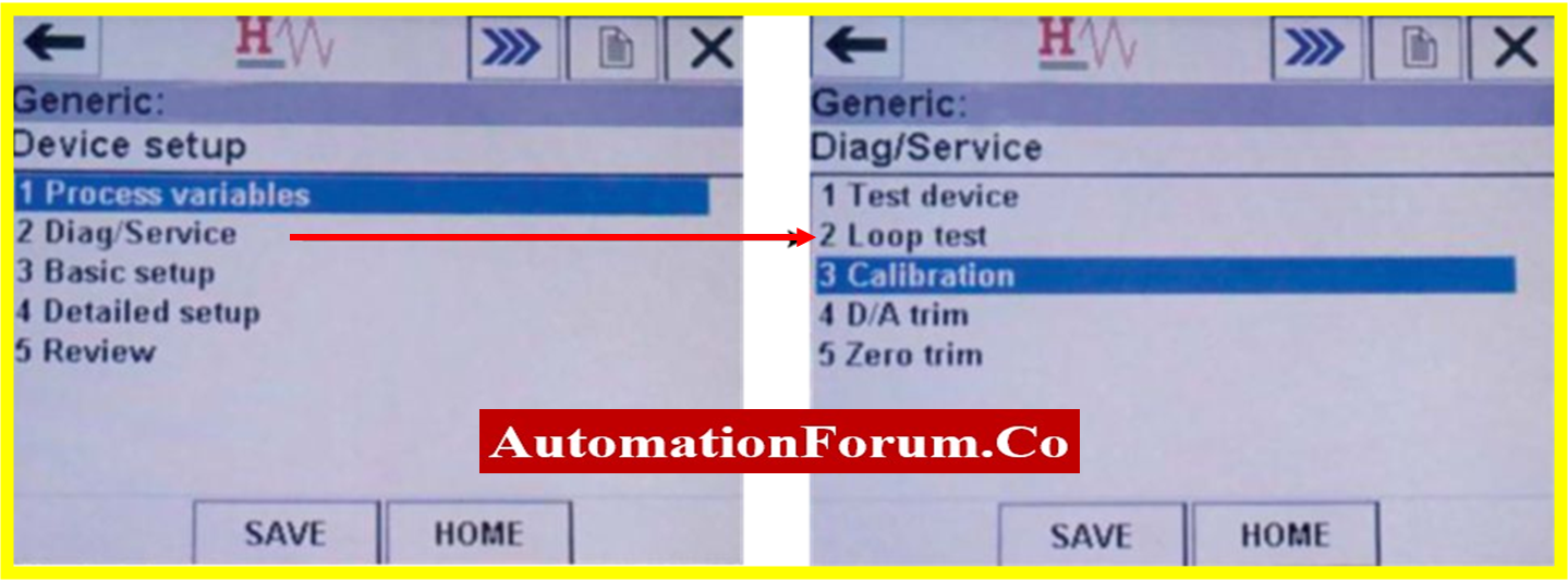
- To display the Calibration screen, use menu option “3 Calibration” from the Diag/Service (Picture left). You can manually enter pressure values or use the measured pressure value from the Calibration window (Figure right). Choose menu “2 enter values” to manually enter the pressure value. Before the edit screen appears, you will be asked to choose between 4mA and 20mA (Figure).
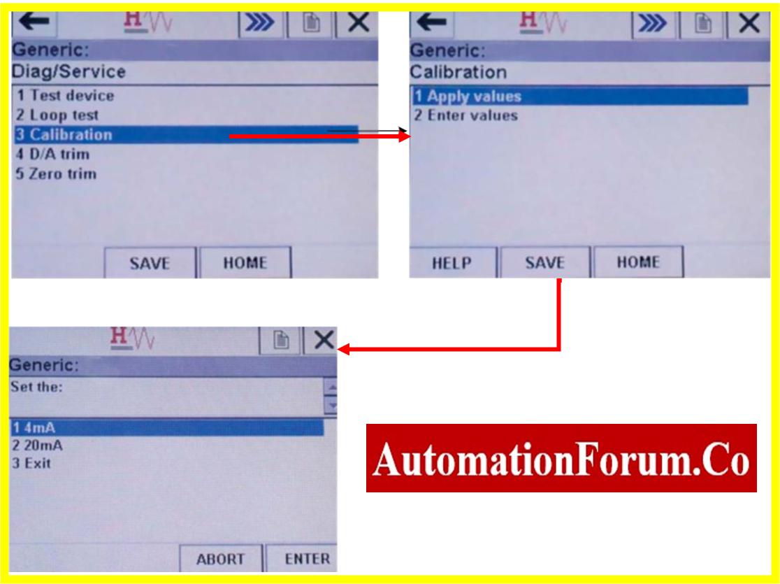
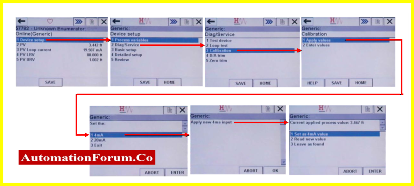
- Choose menu “1 Apply values” from the Calibration screen to set the 4mA or 20mA value to the current pressure (Figure right). Choose the setting you wish to make (Figure left). In the next example, the pressure value of 4mA will be set. The resultant screen when the 4mA value is chosen is shown in Figure (right). After you tap “OK,” the screen in Figure will appear.
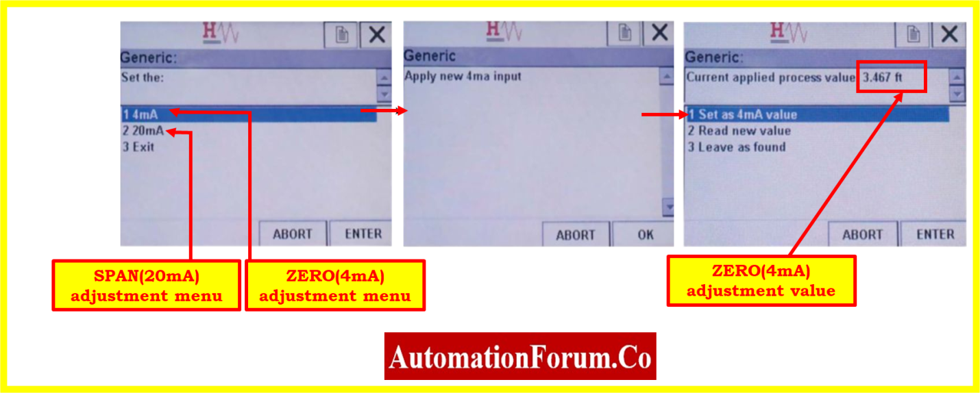
- The top portion of Figure shows the measured pressure. Use the “1 Set as 4mA value” menu option to operate this pressure. If the pressure was out, change the target or wait until the target pressure reaches the required value before choosing “2 Read new value” from the menu. The new pressure from the pressure transmitter will be read via menu option “2”. It should be noted that changing the 4mA pressure will change the loop current to 4mA.
- The loop current may change if the pressure transmitter’s calibration values are modified. It’s possible to see warning screens similar to those in Figure.
- To continue with the calibration change, tap the “OK” button. For the adjustments to take effect, the pressure transmitter unit must receive the changes once they are made to a calibration value on the 475 Communicator. Figure represents the warning screen that appeared following the adjustment.
- The updated value will be written to the pressure transmitter when “SEND” is tapped. The writing procedure will be stopped by tapping “ABORT”

- In the resultant HART status code, a configuration change flag bit is set whenever a calibration value in the pressure transmitter is changed.
- When the flag is detected, the 475 Communicator will present the non-zero status code screen seen in Figure.
- The screen serves as proof that the configuration of the pressure transmitter has been modified.
- The flag will stay set in all status codes sent to the 475 Communicator until the 475 Communicator tells the pressure transmitter to remove the flag.
- By selecting “YES,” non-zero status codes can be discarded.
- When choosing the 20mA option menu, the same steps must be followed to calibrate the 20mA span pressure value with the URV value of 12 bar.
- Repeating the calibration procedure until the transmitter is calibrated to the desired tolerance is necessary.
Recording calibration
- To make sure the pressure transmitter is producing the proper output values, check the linearity of the output at 0%, 25%, 50%, 75%, and 100% in both the upscale and downscale directions.
- If the output value does not fall within an acceptable range, calibration is required. Pressure transmitter has to be serviced or replaced if the output values have once again gone outside of the allowed range.
- If all output values (+/-%) are within acceptable parameters, the pressure transmitter does not require further calibration.
- The output data should be entered in the as found/as left column of the blank calibration report.
Completion of calibration
- Once the calibration has been successfully completed, attach the calibration label on the pressure transmitter.
- When the calibration is complete, clean the test tools and communicator, store them securely, and make a note of the calibration data for subsequent use.
- The pressure calibrators, connections for the pressure transmitter, and other calibration equipment should be removed.
- In the processing area, the connections for the pressure transmitter must be installed. Furthermore, flush the impulse lines, and remove any airlock.
- Check to see if the workplace is clean.
- De-isolate the apparatus.
- Return the bypassed or suppressed pressure transmitter signal to its original level.
- Make sure the pressure transmitter is functioning correctly before using it.
Sample calibration report
The figure that follows demonstrates how a pressure calibrator and multimeter were used as a reference to calibrate a pressure transmitter sample report in a process region.

By selecting the link below, you can get the Excel document that was used to create the pressure transmitter calibration report.