- What is an Instrument loop diagram?
- What sources are required to make a loop diagram?
- What is the purpose of an instrument loop drawing?
- How to read/interpret a loop diagram?
- Various types of Loop diagrams:
- Some Useful Questions related to Loop drawings:
- What is loop number of an instrument?
- What is an instrument loop folder?
- How to create Instrument loop drawing?
What is an Instrument loop diagram?
An Instrument loop diagram (ILD) is constructed for each process control loop. In an automation system, ILDs provide all of the necessary information concerning control loops. The ILDs are also referred to as “Instrument Wiring diagrams.”
The ILD depicts the connection between the field and the control system, as well as the many components participating in the control loop.
Detailed Explanation of Instrument Loop Diagrams:
Each process control loop has an instrument loop diagram (ILD) developed for it. ILDs tell you more about control loops than any other drawing. The ILD is a detailed drawing that shows how field instruments like transmitters, switches, actuators and control valves etc., are connected to the control system. It could be
- Signals between the Control system for field instruments
- Signals between the Control Panel and the control system
- Signal between the MCC and control system
- Signal between one control system to another
The loop diagram shows the instrument (in a symbol) and its terminal numbers that need to be connected, the cable number, the junction box number, the terminal number assigned to the specified instrument, the multipair cable and pair number, the marshalling cabinet number, the terminal number in the marshalling cabinet, and the control system details (rack, slot, I/O channel).
What sources are required to make a loop diagram?
To finish the loop diagram and give full information, the following information is needed, along with its source or reference:
Instrument tag number with terminal number:
It’s likely that most instruments use (+) and (-). terminals. Instruments that need to be set up in a certain way, like smoke detectors or instruments in a series loop, need connection details from the manufacturer to make sure the cable is properly connected.
Junction box terminal number:
You could get this information from the JB wiring connection.
Terminals number in marshalling cabinet:
This information could be found by marshalling drawing wiring connections.
I/O point detail information:
Get this information from the I/O assignment that the system integrator or control system vendor makes.
What is the purpose of an instrument loop drawing?
ILD is used to check that the installation and connections are done correctly during pre-commissioning, commissioning, and operation. It can also be used to troubleshoot the problems.
How to read/interpret a loop diagram?
Below we can see an example of an instrument loop diagram with an analogue input & output from DCS along with digital output from ESD systems:
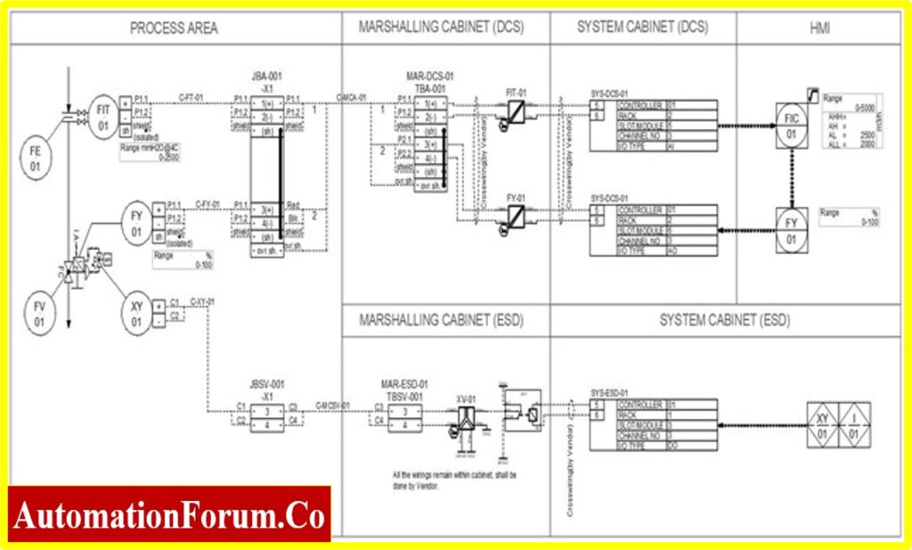
The Instrument loop drawing shown above have two sections field side (process area) and system side (Marshalling & System cabinet and HMI).
1. Field Side:
The field side is divided into two sections. The first is an instrument, whereas the second is a junction box where cables link.
Instrument:
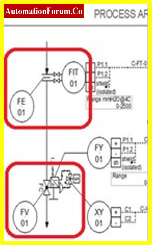
FIT01 represents a Flow Indicator cum transmitter and FV01 indicates a Flow control valve
Junction Box:
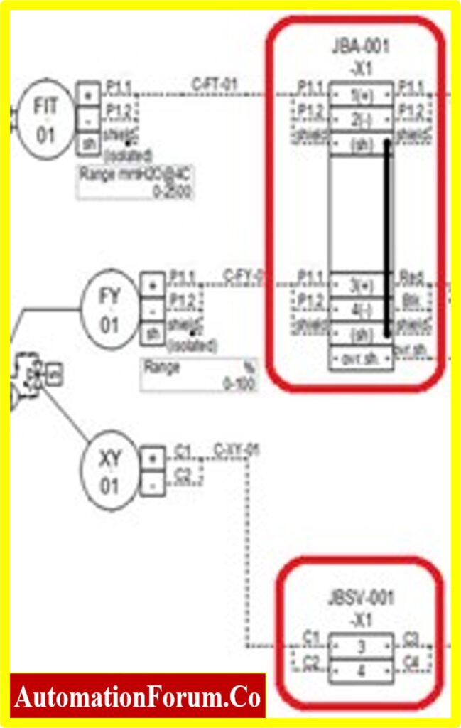
JBA-001 and JBSV-001 represents two different junction boxes.
Where, JBA-001 junction box is connected to FIT01 flow transmitter and FY01 flow control valve on the field side, and DCS system on the system side.
On the other hand, JBSV-001 junction box is connected to XY01 actuator on the field side, and ESD system on the system side.
2. System Side:
The System side is further divided into three sections. The marshalling cabinet, System cabinet and HMI.
Marshalling cabinet:
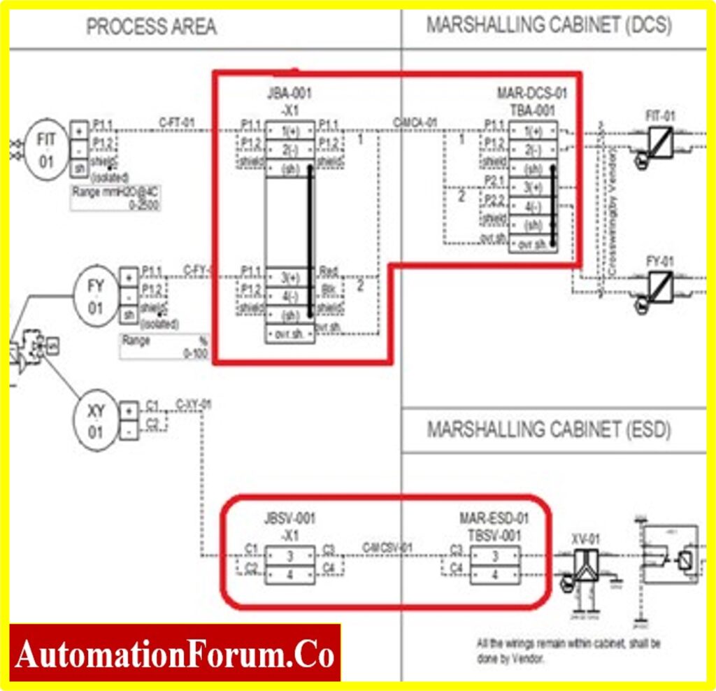
JBA-001 junction box is connected to MAR-DCS-01 DCS Marshalling cabinet through TBA-001 terminal blocks.
On the other hand, JBSV-001 junction box is connected to MAR-ESD-01 ESD Marshalling cabinet through TBSV-001 terminal blocks.
System cabinet:
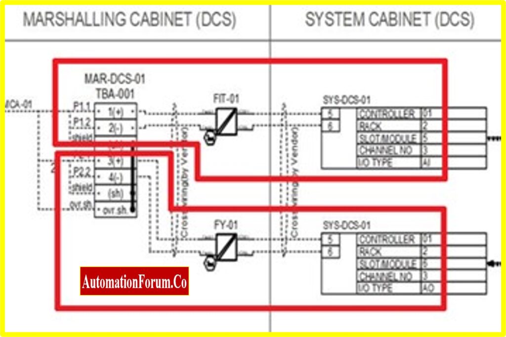
MAR-DCS-01 Marshalling cabinet’s flow transmitter signal (FIT01) is connected to SYS-DCS-01 system cabinet through FIT-01 signal isolator (Barrier) to Analog input module.
Controller: 01
Rack: 2
Slot/Module: 5
Channel No: 3
IO Type: AI
MAR-DCS-01 Marshalling cabinet’s flow control valve signal (FY01) is connected to SYS-DCS-01 system cabinet through FY-01 signal isolator (Barrier) to Analog output module.
Controller: 01
Rack: 2
Slot/Module: 6
Channel No: 3
IO Type: AO
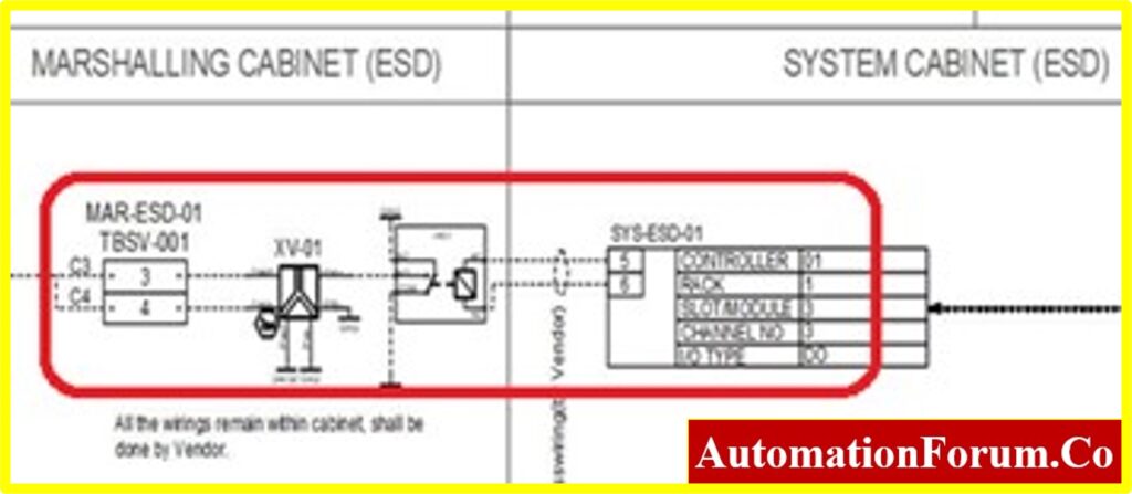
MAR-ESD-01 Marshalling cabinet’s actuator signal (XY01) is connected to SYS-ESD-01 system cabinet through XV-01 signal isolator (Barrier) to Digital output module.
Controller: 01
Rack: 1
Slot/Module: 3
Channel No: 3
IO Type: DO
HMI:
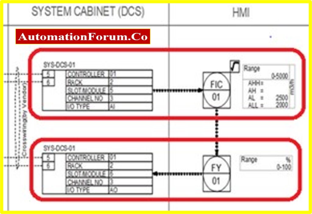
Finally the flow transmitter (FIT01) and flow control valve (FY01) signals are connected to FIC01 and FY01 Analog input and output data points in DCS system and configured the same in Human Machine Interface (HMI) display for monitoring and control purpose.
Various types of Loop diagrams:
- A PCS/DCS loop diagram can be used to show the connection details of field instruments with DCS system.
- Emergency Shutdown (ESD) loop diagram can be used to show the connection details of Safety Instrumented System (SIS) field instruments with ESD system.
- Fire & Gas (F&G) loop diagram can be used to show the connection details of F&G related field instruments with F&G system.
- System Interconnection loop diagram can be used to show the connection details between one control systems to another.
Few of the examples of System Interconnection loop diagram is mentioned below
a) Hardwired signals between DCS and ESD system for tripping purpose.
b) Hardwired signals between DCS and F&G system for alarming purpose.
c) Hardwired signals between DCS and Motor Control room (MCC) system for motor/pump start and stop signals.
d) Hardwired signals between DCS and Interposing Relay Panel (IRP) for motor/pump start and stop signals.
Some Useful Questions related to Loop drawings:
What is loop number of an instrument?
A loop number is an unique number assigned to a specific control loop within a system to identify the control loop.
A control loop is a closed-loop control system that is used to maintain a process variable at a desired setpoint by continuously measuring and adjusting the output of a control system. The loop number may be used to identify and distinguish different control loops within a system.
For example, a manufacturing facility may have multiple control loops to maintain different process variables such as temperature, pressure, flow rate, and so on. Each of these control loops may have a unique loop number to identify it within the system.
The loop number may be used to access and configure the settings of a particular control loop, or to monitor and troubleshoot issues with the control loop.
What is an instrument loop folder?
An instrument loop folder is a document that provides detailed information about a specific control loop within a system. The loop folder typically includes a variety of information, such as the process variables being controlled, the control system components, the control strategies and algorithms being used, and the instrumentation and sensors that are used to measure the process variables.
The loop folder is typically used as a reference document for engineers, technicians, and other personnel who need to understand the details of a particular control loop in order to maintain, troubleshoot, or modify the system. It may also be used as a training resource for new personnel who are learning about the control loop.
In addition to providing detailed information about the control loop, the loop folder may also include diagrams, schematics, and other visual aids to help explain the system and its components. It may also include information about the process being controlled, such as the process flow, the materials being used, and the operating conditions.
How to create Instrument loop drawing?
There are several steps involved in creating an instrument loop drawing (also known as a loop folder or instrument loop folder) for a control loop in an industrial automation system:
Identify the process variables being controlled:
The first step in creating an instrument loop drawing is to identify the process variables that the control loop is responsible for maintaining. This may include variables such as temperature, pressure, flow rate, level, and so on.
Determine the control system components:
The next step is to determine the control system components that are used to maintain the process variables at the desired setpoint. This may include components such as controllers, actuators, and sensors.
Develop the control strategy:
Based on the process variables and control system components, the control strategy should be developed. This involves determining the algorithms and logic that will be used to control the process variables.
Create the loop folder:
Once the process variables, control system components, and control strategy have been identified, the loop folder can be created. This typically involves creating a document that includes detailed information about the control loop, including diagrams, schematics, and other visual aids to help explain the system.
Review and revise the loop folder:
After the initial version of the loop folder has been created, it should be reviewed and revised as necessary to ensure that it is accurate and complete. This may involve input from various stakeholders, such as process engineers, control engineers, and technicians.
Creating an instrument loop drawing is an important step in the design and implementation of a control loop in an industrial automation system. It helps to ensure that the control loop is properly configured and operating as intended, and provides a reference document for maintenance and troubleshooting.