- 7 Steps Procedure for Calibration of Temperature Controller
- Step 1: Prepare the tools required for Temperature Controller Calibration
- Step 2 : Safety Precautions
- Step 3 : Prepare the Calibration Setup for Temperature Controller
- Step 4 : Calibration Procedure
- Step 5: Recording Calibration
- Step 6: Completion of Calibration
- Step 7: Calibration Report Preparation
- Calibration Standards for Temperature Controller
What is a Temperature Controller?
- A temperature controller is a device that controls temperature. This is achieved by first measuring the temperature (process variable), and then comparing it to the desired value (set value). The error (Deviation) is the difference between these values.
- Temperature controllers employ this error to calculate how much heating or cooling is needed to return the process temperature to the intended set value.
- When this calculation is finished, the controller will generate an output signal that will effect the desired change. This output signal is referred to as the (manipulated value) and is typically connected to a heater, control valve, fan, or other “final control element” that injects or removes heat from the operation.

On / Off Temperature Controller (Trip – Emergency cut off)
- On/Off Controllers are temperature controllers that operate by turning a heating or cooling device on or off based on preset temperature limits.
- The Trip, or emergency cut-off, ensures that the system shuts down in critical situations, preventing temperature overshoots or failures, enhancing safety in industrial or process control applications.
7 Steps Procedure for Calibration of Temperature Controller
The comprehensive procedure outlines the step-by-step process for calibrating a thermocouple temperature controller in the process area, utilizing established standards to ensure accuracy and reliability in temperature measurements.
Step 1: Prepare the tools required for Temperature Controller Calibration

- Necessary hand tools.
- Multifunction process calibrator.
- Standard Multimeter.
- Test leads and probes.
- TC Compensation cable and mini TC plug.
- Soft Cloth for cleaning.
Step 2 : Safety Precautions
- Please click on this link for more information about process industry fundamental safety, general recommendations, as well as calibration.
Process Industry Calibration Process: Fundamental Safety and General Considerations
- Request that the panel operator configure the temperature controller signal for the ESD loop in manual mode and also for thermocouple temperature controller trip signal in MOS (Maintenance Override Switch).
- Locate the thermocouple temperature controller that needs to be calibrated.
- Check that the thermocouple temperature controller is the correct one and take note of any essential details, such as the Tag number (e.g., the manufacturer, model number, temperature range, sensor input type, etc.).
- Keep in mind that depending on the temperature controller and process location, this basic procedure may need to be adjusted. When working with a temperature controller or any other kind of process equipment, always follow the instructions provided by the manufacturer as well as regional safety standards.
- To prevent an unintended start, follow all appropriate lockout/tagout procedures. Keep the temperature controller separate from the operation.
Step 3 : Prepare the Calibration Setup for Temperature Controller

- Ensure the calibration area is free from electromagnetic interference and vibrations.
- Verify adequate ventilation and illumination for optimal working conditions.
- Obtain all necessary test equipment and materials for temperature controller calibration.
- Turn off the power to the temperature controller.
- Disconnect any wires or connectors from the local junction box or Marshalling panel, referring to the instrument loop diagram.
- Identify the compensation cable used in the temperature controller.
- Refer to color-coding to locate the cable linked to a different terminal block or connector on the temperature controller.
- Determine the type of connection (screw terminals, spring-loaded terminals, push-in terminals).
- Use the appropriate tool (screwdriver, pliers) to release the connector or terminal holding the compensating cable.
- Carefully remove the compensating cable from the temperature controller, keeping it straight to avoid damage.
- Label the compensating cable for future reference, indicating its position and connection locations.
- Identify the type of thermocouple and compensating cable used in the temperature controller.
- Obtain a limited amount of the same type of cable and a mini TC connector.
- Connect one end of the compensation cable to the TC input terminal of the temperature controller.
- Connect the other end to the thermocouple signal simulation terminal of the process calibrator using a mini plug.
- Use probes and a lead to measure the trip contact output of the controller with a multimeter in resistance mode between the junction box and the thermocouple temperature controller.
- If the temperature controller is smart, connect the communicator to its terminal and establish communication.
- Verify that all connections have been established as per the diagram.
- Ensure cables are securely connected.
Step 4 : Calibration Procedure
Controller Indication calibration
- Examine the stability of the compensation cable simulation input connections and power wire connections of the thermocouple temperature controller.
- Turn on the power supply for the thermocouple temperature controller and verify the presence of power in the controller’s terminal.
- Refer to the instrument data sheet to confirm essential temperature controller parameters such as tag number, type, LRV, and URV.
- Use a communicator for checking parameters in a smart temperature controller.
- Power on the process calibrator and select TC source mode and thermocouple input type.
- Configure the process calibrator’s simulation input range based on the temperature controller’s LRV and URV.
- Select the Cold Junction Compensation (CJC) mode as Internal, External, or Fixed.
- Decide on the type of CJC compensation to use: Fixed, External, or Internal.
- If using the Fixed option, set the temperature to 0°C if an ice bath is employed. If External CJC is chosen, attach a PRT (platinum resistance thermometer) to the process calibrator to monitor the temperature of the ice bath or heat source.
- Generally, internal CJC is the preferred option.
- Check the cold junction compensation (CJC) mode in the calibrator and enable CJC if it’s activated in the temperature controller with an automatic internal sensor.
- When opting for internal compensation in both the temperature controller and the calibrator, position the multifunction process calibrator as close to the temperature controller as possible to minimize CJC compensation error.
- Refer to the compensation data from the communicator or the instrument data sheet.
- Replace the thermocouple with a multifunction process calibrator for calibration, generating a temperature range in millivolts with CJC compensation.
- On older thermocouple temperature controllers, adjust the Zero and Span settings using multi-turn potentiometers. Adjust the Zero pot to create LRV on the controller’s display when the simulated temperature is 0%, and adjust the Span pot to create URV on the display when the simulated temperature is 100%.
- Always refer to the manufacturer’s manual for specific adjustment procedures.
To determine the calibration check point value for linearity checks, utilize this online calibration test points value calculator.
Controller Safety Trip Contact verification
- Power off the temperature controller to prevent unintended activations during the verification process.
- Identify the safety trip contact location on the temperature controller.
- Confirm wiring integrity, checking for loose connections or damaged wires.
- Use a multimeter to measure the resistance across safety trip contact terminals.
- Set up the process calibrator in TC source mode to simulate a fault condition.
- Connect the process calibrator output to the TC input terminals of the temperature controller.
- Power on the temperature controller and initiate the simulation to activate the safety trip condition.
- Verify the safety trip contact response, checking for a change in resistance or continuity.
- Ensure that the safety trip contact changes according to the process setpoint in the controller.
- Verify the setpoint and reset point values inside the controller using the instrument data sheet.
- Check the repeatability of the safety trip contact changeover at the set and reset values.
- In case of errors in the change value, adjust the offset in the controller to bring the set and reset values within the specified tolerance.
- Document the verification results, noting any discrepancies.
- Take corrective actions if any issues are identified during the verification process.
Click here to know more about troubleshooting of process controller
Step 5: Recording Calibration
- Check temperature controller output linearity at 0%, 25%, 50%, 75%, and 100% in both upscale and downscale directions.
- Confirm correct output values on the display and trip contact changeover at set and reset points.
- Measure and record observed values for both upscale and downscale linearity.
- Verify safety trip contact changes at specified set and reset points, noting observed values.
- Use this Instrument accuracy calculator to calculate error and accuracy for each recorded output reading.
- Compare error and accuracy with acceptable ranges; if within limits, no further calibration is needed.
- Fill the “As Found/As Left” column in the calibration report if values deviate.
- Consider servicing or replacing the controller if repeated deviations occur.
- Document all steps, observed values, calculations, and actions taken during calibration.
- Maintain proper documentation for audit and future calibration needs.
- Conclude that the controller is considered calibrated and in working order if it meets standards after calibration.
- Keep records for audit and future calibration requirements.
Click here to get more calibration procedure
Step 6: Completion of Calibration
- Attach the calibration label to the temperature controller after a successful calibration.
- Disconnect the temperature controller, multifunction process calibrators, and other calibration tools.
- Clean and store the test equipment and communicator once the calibration is complete.
- Note the thermocouple temperature controller calibration data for future reference.
- Place back the temperature controller with connections in the processing area.
- Verify the cleanliness of the workplace.
- De-isolate the equipment.
- Restore the temperature controller signal to its bypassed or suppressed level.
- Before use, ensure the temperature controller is functioning properly.
Step 7: Calibration Report Preparation
The provided illustration demonstrates the calibration of a temperature controller in a process area using a multimeter and process calibrator as reference instruments.
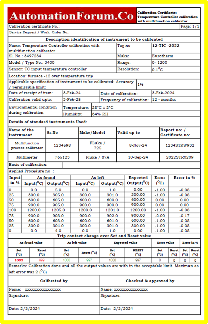
To access the Excel document utilized for generating the temperature controller calibration report, please follow the link below.
Click here for downloadable more instrument calibration templates
Calibration Standards for Temperature Controller
- This temperature controller calibration procedure adheres to ISO/IEC 17025, ensuring the competence of our testing and calibration laboratory. The procedure follows general requirements for accuracy, reliability, and traceability to the International System of Units (SI).
- Our calibration process aligns with the guidelines provided in NIST Handbook 150-5, covering the calibration of temperature-measuring devices, including temperature controllers. This includes procedures, uncertainty estimation, and reporting requirements.