What is a Differential Pressure Transmitter?

The Differential pressure transmitter is commonly used in industries as pressure measuring instrument. It is a device that measures two opposing pressures in a pipe or a vessel. This equipment will sense the difference in pressure between two ports and produce an output signal with reference to a calibrated pressure range. In the Differential pressure transmitter, as flow increases, the differential pressure increases, and when flow decreases the differential pressure decreases.
What are the main parts of Differential pressure transmitter?
A differential pressure transmitter has 3 functional parts,
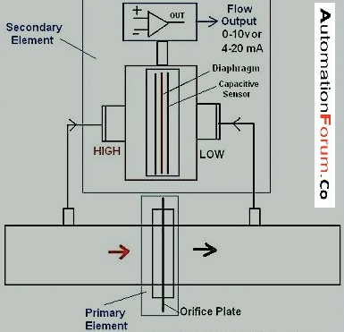
- Direct pressure sensing element (located in lower housing):Almost all differential pressure transmitters are fitted with diaphragm as pressure sensor element. As the diaphragm is mechanical device, it is placed between two pressure inlet ports. The diaphragm will deflect based on the applied pressure and this deflection is converted into an electrical signal. This conversion is usually done by sensors like vibrating wire, strain gauge, differential capacitance.
- Electronic unit:The electrical signal generated at the lower chamber by the sensor is in the range of milli – volt. This is to be amplified to 0-5V or 0-10V, or to be converted to 4-20 milliamps for onward transmission to a remote instrument.
- 2-wire 4-20 milliamp current transmitter:A DC output current is generated that is directly proportional to the pressure range of differential pressure transmitter. The lower range is 4 milliamps and the upper range is 20 milliamps.
How to calibrate differential pressure transmitter?
Materials Required For Calibration
- Data sheet
- 24V dc supply
- Screwdriver toolkit
- Milliammeter
- Pressure calibrator
What is the Procedure to calibrate Differential pressure transmitter?

- An orifice plate is placed to restrict the flow of liquid. This restriction creates a pressure drop. And this pressure drop can be converted to flow rate. The differential pressure here can be defined as the difference in higher pressure reading and lower pressure reading. We can use a low pressure calibrator to furnish and measure input pressure.For measuring the transmitter’s output, a milliammeter is appropriate standard. The calibration includes the following steps,
- Connect the transmitter to the pressure calibrator.
- Give the air supply based on manufacturer’s instructions.
- Connect the output from the pressure calibrator to the high pressure port on the transmitter to provide signal pressure.
- Vent the transmitter’s low pressure port to atmosphere to provide a reference point for the differential pressure measurement.
- To measure the transmitter output, connect a milliammeter to the transmitter.
- Then connect a 24-volt power supply in series with the transmitter and milliammeter.
- Typically, inputs at 10%, 30%, 50%, 70% and 90% of span are used as test points.
- Hysteresis is the tendency of an instrument to give a different output for a given input, depending on whether the input resulted from an increase or decrease from the previous value.
- Often the data from an instrument test is recorded on a calibration data sheet to help identify instrument errors.
- Adjust the zero first, since span error is corrected only after an accurate zero is established. Zero is properly set when a 10% input produces a 10% output.
- Adjust the span at 90%. Since zero and span frequently interact, after one of these errors has been corrected, the other may require readjustment.
- Flow rate which may be represented by Q, is the square root of the calculated pressure drop across a restriction. Q = square root of the Differential Pressure.
- Differential pressure transmitters may include an integral square root extractor, which provides a linear output signal.
- However, if a square root extractor is not part of the transmitter circuitry in the process, a separate square root extractor may be installed in the output signal loop.
- In a loop, a 4-20 mA output from a differential pressure transmitter provides an input to the square root extractor.
- So, in the calibration, a milliamp source would provide an appropriate input standard. The output measurement standard is also a milliammeter.
- To complete the setup, connect a power supply in series with a square root extractor and milliammeter. Manufacturer’s instructions specify the input values and expected outputs.
- The square root of the input determines the output.
Common terms Used in DP Transmitter Calibration
- Lower Range Limit (LRL):This is the lowest value of the measured variable that a transmitter can be configured to measure. This is different from Lower Range Value (LRV).
- Lower Range Value (LRV):Lowest value of the measured variable that the analog output of a transmitter is currently configured to measure.
- Transmitter Re-ranging:Configuration function that changes a transmitter 4 milliamps and 20 milliamps settings
- Upper Range Limit (URL):This is the highest value of the measured variable that a transmitter can be configured to measure. This is different from Upper Range Value (URV).
- Upper Range Value (URV):Highest value of the measured variable that the analog output of a transmitter is currently configured to measure.
- Span:Span is defined as the algebraic difference between the upper (URV) and lower range (LRV) values of the transmitter. Span = URV – LRV .
- Calibration Range:The calibration range of a transmitter is defined as the region between the limits within which quantity is measured, received or transmitted, expressed by stating the lower and upper range values. The limits are defined by the zero and span values of the DP transmitter.
- Instrument range:Instrument range refers to the capability of the transmitter. If the manufacturer has designed a DP transmitter for the range of 0-700 psig, then 0-700 psig is the instrument range of the transmitter.
- MWP:MWP means maximum working pressure of the DP transmitter. It refers to the amount of gauge pressure common to each port and not the differential pressure between the ports.
- Transmitter Damping:Output function that increases the response time of the transmitter to smooth the output when there are rapid input variations.
- Zero Trim:A zero- based one point adjustment used in different pressure applications to compensate for mounting position effects or zero shifts.
What is the purpose of equalizer valve?
Equalizer valves are used to equalize the pressure on both sides of the transmitter.

In a 3- way valve manifold, during the normal operation the equalizing valve is closed and the two block valves (HP and LP) are open. When the transmitter is removed the valves must be operated in such a way that very high pressure is not applied.
In a 5-way valve manifold, during normal operation the equalizing valve and bleed valves are closed and LP,HP are open. It is important the equalizing valves are not open while the HP and LP valves are open. For example if we are handling with hot dangerous fluid, it will lead the fluid to transmitter and manifold and also may lead to any personal hazard.