- Specification of a control valve begins with a control loop.
- The control loop in every industrial application includes transmitters to transmit the signal to the controller then to the positioner and finally to the actuator of the control valve.
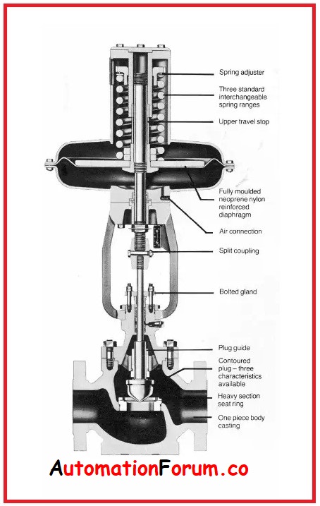
- The valve assembly consists of :
- Positioner to convert electric signal to pneumatic signal.
- Actuator for closing and opening of the valve to regulate the flow of the fluid.
- Control valves in the process industry handle various types of process fluids at all temperatures ranging from cryogenic range to well over 1000 degrees Celsius.
- Control valve plays an important role in increasing plant efficiency and in the conservation of energy.
- Selecting the control valve assembly for particular applications requires some consideration to be taken for providing an appropriate combination of valve body style, material, and trim construction design for the planned project.
- In selecting the right control valve for particular applications, the capacity requirements and operating pressure ranges of the system must also be considered to ensure satisfactory operation with improved efficiency.
- For given service conditions, it is important to consider a piece of serious advice from the control valve manufacturers and their sales representatives in selecting the most appropriate control valve.
- There are several choices of selection of a control valve for a specific application; However, this requires the right set of information.
- The valves are available in various models with unique features, advantages, and limitations.
Some information shown below indicates the required criteria that need to be followed to select the right control valve for the specific application.
Application Information:
- Inlet pipe diameter and schedule.
- Outlet pipe diameter and schedule
- Special tagging information if required.
- Valve body material
- End connections
- Valve rating.
Process Information:
- Fluid type
- Temperature of fluid
- Viscosity of fluid
- The specific gravity of the fluid
- Maximum and Minimum low capacity
- Maximum and Minimum valve Inlet pressure
- Maximum and Minimum valve Outlet pressure
- Pressure drop during normal flowing conditions
- The maximum permissible noise level
- Degrees of superheat.
Valve Trim Information:
- Valve type
- Valve size
- Valve body construction.
- Valve plug guiding Valve plug action
- Port size
- Valve trim materials required
- Flow action
- Bonnet style.
Actuator Information:
- Actuator size
- Instrument air supply pressure
- Instrument control signal
- Fail action desired on the failure of instrument air
Valve Accessories Information:
- Positioner type if required
- Limit Switches if required – type, indication, etc.
- Solenoid Valve
The selection of valves depends on their ability to perform specific functions such as
- It must be able to throttle or control the flow rate.
- Lack of turbulence to flow when fully open
- A quick operating mechanism, during emergency rapid response for safety, is needed
- Tight shut-off to prevent leakage
- Ability to flow in one direction.
- Ability to handle abrasive fluids because hardened material prevents rapid wear and tear.
- Must operate over a wide flow range.
What are the tips followed for the selection of a valve?
The following tips must be followed when selecting a valve.
- The valve must be selected such that it must allow maximum flow when 90% open.
- The valve must be selected such that it must allow minimum flow when 10% open.
- The valve must be selected such that it must allow normal flow when 60-70% open.
- Size the control valves that must absorb up to 30% of the total (Range) pressure drop.
- Control valves must not be less than 50% of the pipe size.
- The valve proposed for shut-off service must line size.
- If the diameter of the line is 1 inch then the valve size must be equal to the size of the line.
- If the diameter of the line is larger than 1 inch, the valve size must be 1 inch only.
- The valves used must have a flanged connection proposed for the line must have a nominal diameter smaller or equal to 1.5 inches as per 300 ANSI rating.
- The valve body and trim material must be selected to match the impeller and pump casing in case of corrosive fluid.
- Fluid velocity must be least as much as possible in the case of abrasive materials. For clean fluids, the line velocity must be about 10 ft/s.
- To control the process pressure, keep sensing the pressure continuously because most of the sensors may not function accurately.
- If transducers are used in a control loop, the positioner must be specified to the valve to avoid the robbing of actuator thrust by transducers that leads to valve leakage.
- Allow a straight run of downstream pipe after control valve in cavitating fluid for the valve having cavitation trim.
What terms are related to the control valve selection?
The terms related to valve selection are summarized below.
Generally, the valve moves to a position directed by the controller signal called controller output. if the valve is a physical device and its performance is not ideal the following factors prevent the ideal performance of the valve.
Dead band:
- A control valve having a dead band behaves like having backlash between valve position and controller output. But the valve position is changed only by the controller.
- The dead band is caused by mechanical backlash and excessive friction in the valve, an undersized actuator, or a defective positioner.
Resolution:
- It is the smallest amount of change in the signal keeping the stem position constant.
- Backlash and Stiction are the two major causes of non-ideal valve behavior
- Backlash is a relative movement between interacting parts.
- Stiction is a resistance to the start of motion required to defeat static friction.
- If a valve halts the movement, then it tends to remain in its present position even if the controller tries to change the output.
- Now to overcome this stiction an additional force is required.
- To defeat static fiction, if the pressure is raised then the valve breaks.
- The valve movement will absorb the excess pressure immediately,
- Over-tightening of valve stem seal causes Stiction in the valve by sticky valve internals, an undersized actuator, or a sticky positioner. The addition of a valve positioner improves the precision of a valve.
Noise:
- When the valves are subjected to high-velocity turbulent flow, the valve component tends to vibrate.
- At a high flow rate, the standard control valves make noise on higher pressure drop applications.
- The minimum pressure downstream of the seat ring at the vena contracta is maintained by very high velocities like the speed of sound.
- A silencer or heavier wall pipe is used as insulation to reduce noise levels lesser than 100 dB.
- Labyrinth plugs, multi-step angle valves, or flow restrictor in series with the valve is required to treat noise level higher than 100 dB that creates dangerous pipe vibration.
Upstream pressure:
- Upstream pressure in a control valve is increased for incorrect sizing.
- Fluid velocity at the upstream side of the valve will be minimum which causes a rise in pressure.
- This increase in upstream pressure may be harmful to some processes like membrane filtration where a higher pressure difference is desired.
- If pressure at the penetration side of the membrane is increased, there is a reduction in driving force.
Hysteresis:
- It is an assumption that a control valve is dependent on its initial valve position.
- A common valve opening corresponds to different flow rates depending upon the position of the valve if opened or closed.
- To obtain the desired flow rate, the position of a valve stem is changed in a control system.
- If hysteresis goes high, it causes the control architecture to force a system to oscillate around the desired point.
Flow coefficient:
- Flow coefficient is the most important parameter considered during the selection of the control valve for calculating the size
- Calculation of flow coefficient Cv depends upon whether the fluid flowing is incompressible, compressible, or mixed-phase.
Fire – safe:
- In many process applications, it is required to reduce or avoid the leakage of dangerous products.
- A valve that satisfies effective shutoff of the valve is known as fire-safe.
- The term fire-safe in the valve specification is one of the least understood.
- But till now there is not any test equipment available to certify the valve for a fire safe.
- Metallic gate valves and globe valves are grouped as fire safe because these valves will not melt by fire.
- Butterfly valves are designed with a soft seat over metal to achieve a fire-safe application.
- The design and construction of these valves assure metal-to-metal seating before, during, and after a fire.
- Project engineers must always consider the production cost while designing its design and operations decisions.