- What Is an FRL Unit in Pneumatic On Off Control Valve Service?
- Why FRL Selection Matters for On Off Control Valve Applications
- Application Background of FRL Units in Pneumatic Valve Packages
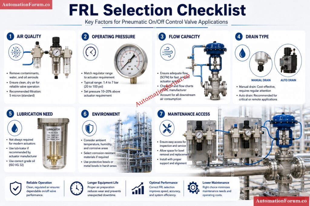
- Step by Step FRL Selection Procedure
- Step 1. Identify the Valve and Actuator Type
- Step 2. Confirm Air Supply Source and Air Quality
- Step 3. Check Actuator Size and Air Consumption
- Step 4. Identify the Operating Pressure Requirement
- Step 5. Determine Whether Lubrication Is Required
- Step 6. Select the Filter Type and Rating
- Step 7. Choose the Drain Arrangement
- Step 8. Confirm Flow Capacity and Port Size
- Step 9. Review Environmental Conditions
- Step 10. Check Accessibility for Commissioning and Maintenance
- Step 11. Confirm Spare Part Strategy
- Filter Selection Details for Instrument Air FRL Selection
- Regulator Selection Details for Pneumatic On Off Valve Service
- Lubricator Selection Details for FRL Units
- Sizing and Selection Guidance for FRL Units
- Example FRL Selection Scenario for a Spring Return On Off Valve
- Installation and Commissioning Requirements for FRL Units
- Maintenance and Troubleshooting Relevance of FRL Selection
- Best Practices for FRL Selection in EPC Projects
- Advanced Engineering Workbook: FRL Unit Selection & Commissioning Checklist
- Conclusion:Key Factors in FRL Unit Selection
- FAQ on FRL Unit Selection
- What are FRL units?
- What is the full form of FRL?
- What is FRL used for?
- How to select FRL unit?
- How to choose the right FRL?
- What is meant by FRL unit?
- What is the FRL unit in air preparation?
- What is the purpose of an FRL unit in a pneumatic on off valve package?
- Is a lubricator always required in instrument air FRL selection?
- What is the most important factor in FRL selection?
- Why is flow capacity important in on off valve service?
- When should a coalescing filter be used?
- Why does drain type matter?
- Can poor FRL selection cause solenoid valve failure?
- What should be checked before final FRL selection?
What Is an FRL Unit in Pneumatic On Off Control Valve Service?
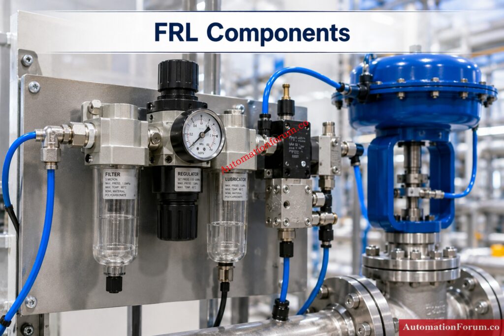
An FRL unit is an air preparation assembly made up of a filter, regulator, and lubricator. In pneumatic on off control valve service, it conditions compressed air before the air reaches the solenoid valve and actuator. In simple terms, the FRL unit helps deliver the right air quality and the right pressure so the valve can open and close reliably.
Why FRL Selection Matters for On Off Control Valve Applications
For EPC engineers, commissioning engineers, and maintenance engineers, the FRL unit selection procedure for on off control valve applications is not a small detail. It directly affects valve response time, actuator life, solenoid valve reliability, startup performance, and long term maintenance effort. A poor FRL selection can create slow stroking, pressure drop, water carryover, sticking solenoids, and repeated troubleshooting calls. A correct selection gives stable operation, better fail action performance, and fewer surprises during commissioning and plant operation.
Application Background of FRL Units in Pneumatic Valve Packages
A typical pneumatic on off valve package includes the instrument air supply, a local isolation valve, the FRL unit, a solenoid valve, the pneumatic actuator, and position feedback devices such as limit switches or proximity switches. In some packages, a filter regulator unit is used without a lubricator. In other packages, a complete filter regulator lubricator assembly is installed, but only when lubrication is actually needed.
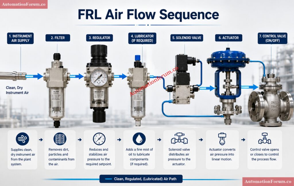
The instrument air enters the FRL unit first. The filter removes dust, rust, scale, and moisture. The regulator reduces and stabilizes pressure to the required level. If required by the equipment design, the lubricator adds controlled oil mist to the air stream. The conditioned air then reaches the solenoid valve and actuator.
From an FRL selection point of view, on off valve service is different from modulating control valve service. A modulating valve needs continuous and highly stable positioning air. An on off valve normally remains fully open or fully closed and only moves during a command. Even so, it still needs fast and dependable air delivery. The FRL must therefore support both clean air quality and the required flow capacity. In field service, many problems that look like actuator faults are actually air preparation problems.
Stop Guessing Delay Logic: PLC Timer Basics Explained: Understanding ON Delay and OFF Delay Timers in PLC Programming
Step by Step FRL Selection Procedure
Step 1. Identify the Valve and Actuator Type
Start with the valve data sheet and actuator data sheet. Confirm whether the actuator is spring return or double acting. Confirm the fail action, whether it is fail close, fail open, or fail in place. Also confirm the required operating pressure and stroke time.
This step matters because the actuator drives the entire air demand. A spring return actuator needs enough pressure to compress the spring and complete the stroke. A double acting actuator needs air for both directions and usually consumes more air. For emergency shutdown or critical isolation valves, the FRL must support the required stroke time even under the least favorable operating conditions.
Step 2. Confirm Air Supply Source and Air Quality
Check the plant instrument air header pressure, dew point, moisture level, oil carryover, and contamination condition. The best FRL cannot compensate for a badly maintained air network. Clean dry instrument air is the ideal supply for pneumatic valve service.
This step matters because dirty air is one of the most common reasons for pneumatic failures. Water can corrode internals and freeze in cold areas. Dirt can block solenoid passages. Oil carryover can damage seals and collect inside components. If the plant air system is old, wet, or contaminated, the FRL selection must be more conservative.
Step 3. Check Actuator Size and Air Consumption
The air demand is a function of the actuator volume and stroke frequency. Check the size of the cylinder or diaphragm, the travel of the actuator, the number of cycles predicted and the response time necessary. Larger actuators and quick stroking valves are demanding more air, in less time.
This phase is important because the FRL must pass enough air without being a pressure bottleneck. Even if the supply gauge reads the correct pressure, a valve may still not react properly. The problem may be insufficient flow under dynamic conditions. For this reason, flow capacity is just as important as pressure rating.
Win Safer Level Transmitter Selection with This Checklist: Level Transmitter Selection Checklist for EPC Engineers – Step-by-Step Guide
Step 4. Identify the Operating Pressure Requirement
Confirm the minimum pressure required at the actuator, the usual working pressure, and the maximum permitted pressure. Then select a regulator range that will position the required set point at the center of the adjustment band.
This is important because a regulator that is operating near the edge of its range is harder to modify and less stable with changes in demand. Pressure stability is useful for complete stroke movement and consistent response time in on-off valve function. When the valve is actuating, pressure droop can cause it to move slowly or not achieve full travel.
Step 5. Determine Whether Lubrication Is Required
Do not assume that every pneumatic valve package needs a lubricator. Many modern solenoid valves, actuators, and accessories are designed for clean dry air and should not receive oil mist unless the manufacturer specifically approves it.
This step matters because unnecessary lubrication can create more problems than it solves. Over lubrication can contaminate solenoid valves, attract dust, foul seals, and complicate maintenance. In many modern plants, the better choice is a filter regulator arrangement without a lubricator. The final decision should always follow the actuator and valve manufacturer recommendation.
Step 6. Select the Filter Type and Rating
The filter should be selected based on the contamination risk and the sensitivity of the downstream equipment. A standard particulate filter may be enough where the instrument air system is already clean and dry. A coalescing filter may be better where fine oil aerosols, moisture droplets, or very small particles are present.
This step matters because the filter protects the solenoid valve, regulator, and actuator from wear and blockage. If the air is dirty, a finer filter is justified even if it creates slightly more pressure drop. The real objective is reliable operation, not minimum initial cost.
Beat Harsh Conditions with Smarter Valve Selection: Control Valve Selection and Recommended Practices for Harsh Process Conditions
Step 7. Choose the Drain Arrangement
The drain type should match the condensate risk and the maintenance access. Manual drains work when the unit is easy to reach and the plant has regular inspection discipline. Semi automatic or automatic drains are better where access is poor or moisture generation is frequent.
This step matters because poor drainage leads to water accumulation in the bowl, then water carryover downstream. In humid or outdoor service, this can quickly affect solenoid valves, pressure stability, and actuator performance. Drain selection should be treated as a reliability decision, not a minor accessory choice.
Step 8. Confirm Flow Capacity and Port Size
Do not select the FRL only by looking at port size. Two units with the same connection size can have very different flow performance. Check the rated flow, pressure drop characteristics, and internal restriction.
This step matters because the valve must move quickly and fully. A high demand actuator or a valve with a short stroke time needs a unit with enough flow margin. Long tubing runs, multiple valve stations, and simultaneous valve operation increase the air demand further. If the FRL is small, the system may experience sluggish reaction, low actuator force or incomplete stroke.
Make Pressure Transmitter Manifold Selection Easy and Accurate: Key Considerations for Pressure Transmitter Manifold Selection
Step 9. Review Environmental Conditions
Identify the location of the unit: inside, outside, coastal area, dusty cement plant, humid tropical environment, or corrosive process area. Environment determines bowl material, body finish, seal longevity and maintenance frequency.
This step is important because the same FRL can work well in one domain and fail early in another. Outdoor and corrosive environments often require better material selection and stronger protection. Maintenance life is part of selection, not something to think about after failure.
Understand Turndown Ratios Before Pressure Errors Hit: Rangeability vs. Turndown Ratio and their Implications for Pressure Transmitter Selection
Step 10. Check Accessibility for Commissioning and Maintenance
The FRL should be installed where the gauge can be seen, the drain can be reached, and the filter element can be replaced safely. If the unit is difficult to access, it will not be maintained properly.
This step matters because inaccessible equipment tends to be ignored until it fails. Good access improves inspection, drainage, troubleshooting, and preventive maintenance. In plant work, accessibility is a reliability feature.
Know the Essential Control Valve Standards That Matter: Codes and Standards for Control Valve Selection in Industrial Applications
Step 11. Confirm Spare Part Strategy
Before finalizing the selection, define the spare parts plan. Check the availability of filter elements, drain kits, bowl seals, pressure gauges, and replacement units.
This step matters because critical valve service cannot wait for long lead times. A standardized FRL arrangement also simplifies stock keeping and maintenance training.
Fix Shutdown Valve Failures Before They Spread Fast: How to Troubleshoot On-Off / Shutdown Valve
Filter Selection Details for Instrument Air FRL Selection
The filter is the first barrier between the plant air supply and the valve package. It must remove contaminants before they can enter the regulator or solenoid valve. For clean instrument air service, a standard filter can be sufficient. For poorer air quality, a coalescing filter may be a better choice because it captures finer contamination and moisture aerosols more effectively.
Dirty air can create several field issues. A solenoid valve may stick or fail to shift. The regulator may clog or drift. The actuator may move slowly or inconsistently. The filter is therefore a core part of instrument air FRL selection, not just a protective accessory.
Drain performance is just as important as filtration performance. If the bowl fills with water, the filter cannot protect the downstream equipment. For this reason, the drain type should reflect the expected condensate load, the operating environment, and the maintenance routine.
Unlock Better Flow Meter Choices for Process Plants: Flow Measurement Selection in Application Scenarios for Process Industries EPC Design Engineering
Regulator Selection Details for Pneumatic On Off Valve Service
The regulator should deliver stable downstream pressure during both idle and active valve operation. For on off control valve service, the main concern is not fine control accuracy, but pressure stability under sudden air demand.
A good regulator should have:
- Stable set point adjustment
- Acceptable droop under demand
- Adequate flow capacity
- Good repeatability after reset
The set pressure should not be selected too close to the low or high end of the regulator range. A mid range operating point generally gives better stability and easier commissioning. In applications with fail close or fail open action, stable regulator performance is essential because the actuator must reach the safe position quickly and fully.
Pressure drop in the air circuit should also be considered. Long piping, small tubing, dirty filters, and undersized regulators all reduce the air available at the actuator. The practical result is slower response, weaker stroking, and lower reliability.
Pick the Right Anti-Surge Valve Without Regret: Anti-Surge Control Valve Selection and Sizing – Complete Engineering Guide
Lubricator Selection Details for FRL Units
A lubricator should only be used when the equipment clearly needs it. Some older pneumatic devices may benefit from lubrication, but many modern actuators and solenoid valves are designed for clean dry air and should not be oiled.
Over lubrication is a real field problem. It can contaminate solenoid valves, create sticky deposits, collect dust, and interfere with downstream components. If the lubricator is not required, it should be omitted from the design. If lubrication is required, the compatibility of every downstream item must be confirmed first.
For most modern on off valve packages, the safer and more common arrangement is a filter regulator unit without lubricator. This is especially true when the plant instrument air is already dry and well maintained.
Compare Control Valves Faster: Find the Best Fit: Globe vs Ball vs Butterfly Control Valves Complete Comparison Guide for Flow Control Selection
Sizing and Selection Guidance for FRL Units
FRL sizing should be based on actuator air volume, cycle frequency, supply pressure, and required stroking speed. The air demand of the actuator should be compared with the flow performance of the FRL, not just the connection size.
A practical selection margin should always be included. This margin helps compensate for filter loading, line losses, minor system deterioration, and future operating changes. Long air lines increase resistance and delay the response. Multiple valve stations on the same branch line can also create temporary demand peaks. In those situations, a higher flow FRL is often the better engineering choice.
The key point is simple. A pneumatic valve package should not be designed to work at the limit of the FRL capacity. It should operate comfortably within the available flow range.
Avoid Costly Mistakes in Control Valve Materials: Control Valve Body Material Selection Guide for EPC Design Instrumentation Engineers
Example FRL Selection Scenario for a Spring Return On Off Valve
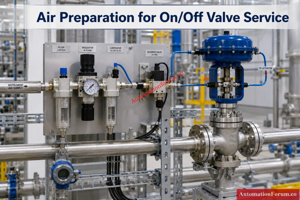
A spring return on off valve in a water treatment plant is used for isolation duty. The actuator requires 5.5 bar operating pressure, the plant instrument air header is at 7 bar, the valve is installed outdoors, and the actuator manufacturer says lubrication is not required.
A practical choice would be a filter regulator unit without lubricator, with good moisture removal capability, an automatic drain, and corrosion resistant construction suitable for outdoor use. The regulator should be set near the required working pressure, and the unit should have enough flow margin to allow quick stroke movement. This choice protects the solenoid valve, supports the actuator reaction time and decreases the effort of maintenance.
Test Your Instrumentation Skills with Tough Flow MCQs: Advanced Flow Measurement Selection MCQs for EPC Instrumentation Design Engineers
Installation and Commissioning Requirements for FRL Units

- Install the FRL in the proper flow direction and in the orientation indicated by the manufacturer.
- Keep the gauge in sight and the drain open.
- Provide an isolation valve upstream so the unit can be maintained safely.
- Before startup, clean the air line thoroughly. Remove rust, dust, dampness and welding slag.
- Pressure test and leak check entire air circuit after installation.
- During commissioning check regulator set pressure, actuator response time and correct fail position of valve.
- Do not limit the commissioning check to electrical signal confirmation. Valve has to be stroked fully and physically seen.
- Record the final pressure setting, filter type, drain type and any special notes in the commissioning records. This helps in planning for future troubleshooting and maintenance.
Calculate Actuator Sizing Like a Pro Engineer: Valve Actuator Sizing Calculator – Complete Engineering Guide
Maintenance and Troubleshooting Relevance of FRL Selection
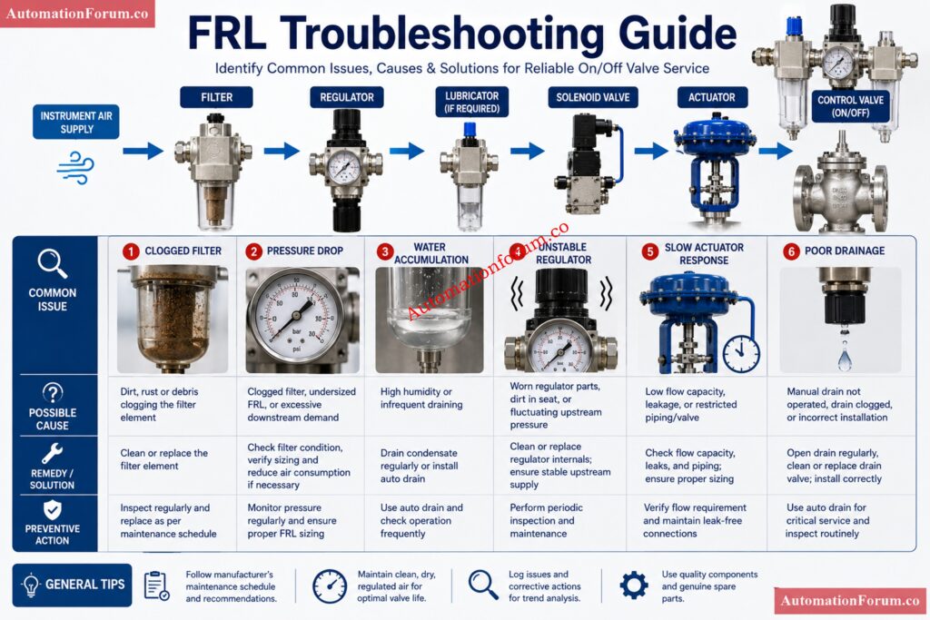
- Slow reaction, pressure reduction or weak actuator movement are often symptoms of a blocked filter.
- Faulty regulator may cause pressure drift, instability, or failure to maintain the set point.
- A poor drain arrangement often causes water accumulation, rust contamination, and poor air quality downstream.
- Typical symptoms of bad FRL selection include valve chatter, slow opening, slow closing, failure to open, failure to close, and solenoid valve malfunction.
- If the valve package is difficult to maintain or difficult to inspect, the risk of future failure becomes much higher.
- A practical preventive maintenance routine should include filter element inspection, bowl drainage, regulator gauge verification, leak checking, and replacement of worn seals or drains. Good pneumatic valve maintenance starts with good air preparation.
Select Hybrid Level Sensors with Total Confidence: Hybrid Level Measurement Selection Procedure for EPC Instrumentation Engineers
Best Practices for FRL Selection in EPC Projects
- For EPC projects, standardize the FRL selection philosophy across similar valve packages.
- This improves consistency and reduces spare parts variation. Keep the FRL close enough to the actuator to minimize pressure loss, but never at the cost of poor access.
- Use clean dry instrument air wherever possible. Avoid selecting a lubricator unless there is a clear technical need.
- Verify flow capacity instead of relying only on port size.
- Check environmental conditions carefully. Make sure the final arrangement is serviceable after installation.
- The best practice is to treat FRL selection as part of overall control valve commissioning and reliability planning, not as a minor piping accessory.
Choose the Perfect Thermowell Before Problems Start: Thermowell Selection Procedure – Complete Guide for EPC design Engineers
Advanced Engineering Workbook: FRL Unit Selection & Commissioning Checklist
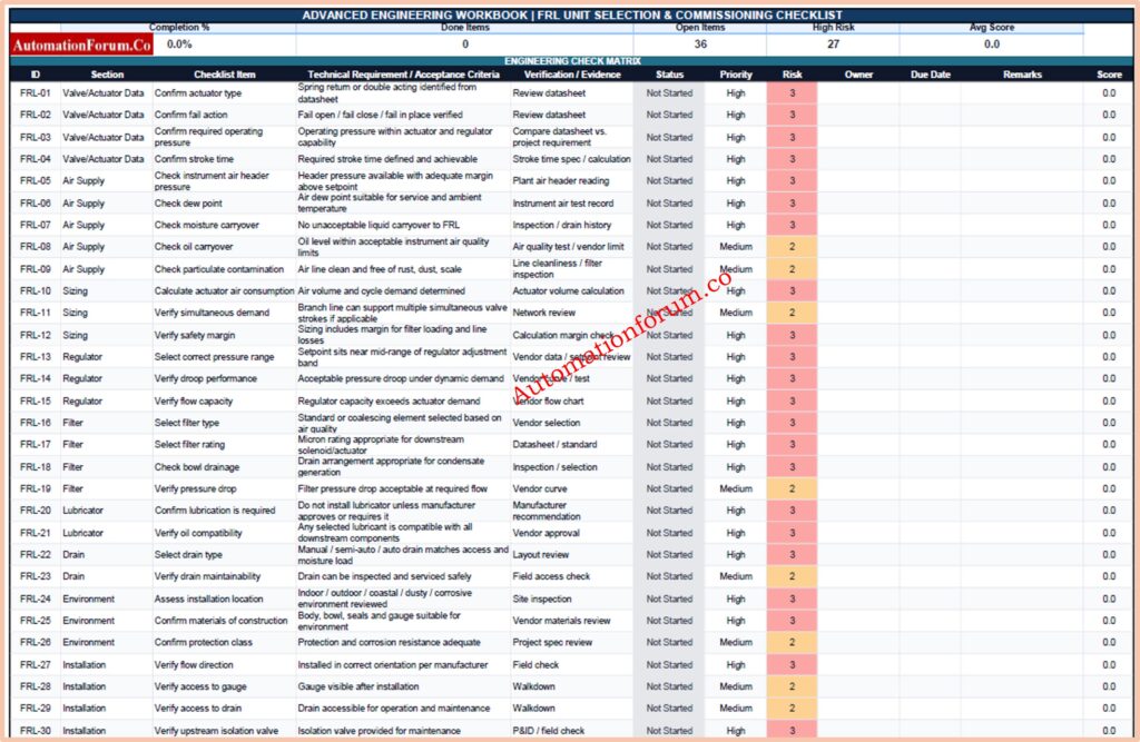
This single-sheet workbook is built for engineering review, selection, commissioning, and maintenance tracking of FRL units in pneumatic on/off control valve service. It includes a structured checklist, status tracking, risk review, and a clean professional layout suitable for EPC and plant use.
Challenge Yourself with Hard Flowmeter Selection Questions: Advanced Flowmeter Selection Quiz for EPC Engineers in Process Industries
Conclusion:Key Factors in FRL Unit Selection
The FRL unit selection procedure for on off control valve service is a practical engineering exercise that affects the performance of the entire pneumatic valve package. The correct selection depends on actuator type, air quality, operating pressure, lubrication need, drain arrangement, flow capacity, environmental conditions, and maintenance access.
When the FRL unit is selected properly, the valve responds faster, the solenoid valve stays protected, the actuator performs more reliably, and maintenance becomes easier. For long term operation, the final choice should always follow actuator and valve manufacturer recommendations, project standards, and actual site conditions.
Streamline Flowmeter Picking with Smarter Engineering Tactics: Streamlining Your Flowmeter Selection Process: Tips and Insights
FAQ on FRL Unit Selection
What are FRL units?
FRL units are air preparation devices consisting of a filter, regulator, and lubricator.
They prepare compressed air before it goes to pneumatic equipments .
What is the full form of FRL?
FRL = Filter Regulator Lubricator.
It is the most popular air preparation assembly in pneumatic system.
What is FRL used for?
An FRL device eliminates impurities, controls pressure and supplies lubricant as needed.
It is useful for ensuring proper operation of pneumatic valves and actuators .
How to select FRL unit?
Choose FRL based on actuator needs, air quality, operating pressure and flow demand.
Consider also environmental conditions and maintenance requirements.
Use the Right Cable Gland in Hazard Zones: Cable Gland Selection for Hazardous Area Installations – Complete 2025 Guide
How to choose the right FRL?
Select a FRL that suits the actuator air consumption and the quality of the plant instrument air.
Always adhere to valve manufacturer guidelines and project standards.
What is meant by FRL unit?
An FRL unit is a compressed air cooling unit used in pneumatic systems .
It conditions air before it enters control devices and actuators.
What is the FRL unit in air preparation?
FRL unit is the last stage of air preparation before the pneumatic equipment.
It provides clean, regulated and application appropriate pressurized air.
What is the purpose of an FRL unit in a pneumatic on off valve package?
It also provides clean and stable air to the actuator and solenoid valve.
This increases the reliability, response time and service life of the valve.
Is a lubricator always required in instrument air FRL selection?
No, many modern pneumatic actuators and solenoid valves operate with clean dry air only.
Lubrication should be used only when recommended by the equipment manufacturer.
What is the most important factor in FRL selection?
The actuator operating pressure and air consumption are usually the primary considerations.
Air quality and required flow capacity are also critical selection factors.
Why is flow capacity important in on off valve service?
Adequate flow capacity allows the actuator to stroke at the required speed.
An undersized FRL can cause slow operation and pressure loss.
When should a coalescing filter be used?
A coalescing filter should be used when fine oil mist or moisture aerosols are present.
It provides higher air quality than a standard particulate filter.
Why does drain type matter?
The drain is intended to drain collected water and impurities from the filter bowl.
Proper drainage prevents moisture reaching the pneumatic equipment downstream.
Can poor FRL selection cause solenoid valve failure?
Yes, dirty air and pressure changes can damage the solenoid valve internals.
The biggest improvement for solenoid dependability is proper FRL selection.
What should be checked before final FRL selection?
Check actuator type, operating pressure, flow requirement, air quality, environment.
Also check maintenance access and manufacturer guidelines before finalising a choice.
Refer the below link for the Interface Level Measurement Selection Procedure – Complete 2025 Guide for Process Engineers