Process control systems rely on control valves as critical parts which control fluid flow to achieve necessary process conditions. Many operational factors determine control valves’ performance while these factors guarantee safe and efficient operation of these critical system components. The document establishes details about essential control valve performance aspects from deadband through actuator-positioner design to response time, valve trim, dead time, gain, hysteresis, inherent characteristics, shaft wind-up, valve capacity, relative flow capacity, fail-safe action and valve seat leakage class. Analyzing these parameters becomes fundamental to maximize control valve performance and establish efficient process control measures.
Dead Band & Backlash
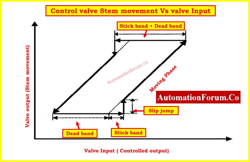
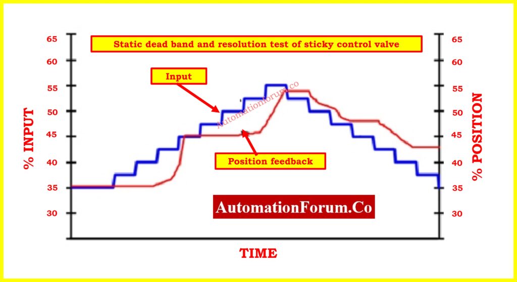
Control valve performance heavily depends on deadband which stands as one of its essential influencing factors. A control valve lacks the capacity to adjust measured process variable (PV) through reversing controller output (CO) values in its operational range. Control valves experience deadband primarily because of mechanical problems which include friction together with backlash and shaft wind-up and relay dead zones. Data from Fisher-Rosemount (1999) specifies deadband as “the input signal range which allows variations before the output signal shows detectable alterations” during signal direction changes.
A load disturbance triggers the process variable (PV) shift away from the setpoint leading the controller to activate its corrective measures. The process variable remains stable after a controller output alteration when the control valve contains a notable deadband. The process variable responds only after the controller output reached the deadband destination. The time it takes for changes to register will increase the variability of the process while lowering its control capabilities.
Devices experience backlash as a restricted deadband condition which develops between their input and output following brief interruptions when their control input direction varies. The valve assembly develops such incorrect movement because it contains mechanical slack or loose components. A rotary valve shows backlash when the actuator rotates backward and the valve shaft fails to track immediately because of mechanical linkage slack.
Deadband and backlash create serious problems for control valves since nearly all control processes demand tiny modifications (1% or less). Valves with extended deadband areas will negatively affect process control functions by missing small signal changes. The presence of deadband in control valves ranges up to 5% or higher levels which substantially affects process performance. Results from ongoing plant inspections reveal that 30% of control valves show deadbands worse than 4% with 65% of all control loops presenting deadbands above 2%.
Essential: Checklist for Troubleshooting Control Valve in DCS Loop
Actuator-Positioner Design
Control valve static and dynamic performance depends heavily on the design choices made for actuators and positioners. The actuator operates the valve closure member (e.g., plug, ball, or disk) based on control signals and the positioner controls rapid and precise valve movement to the required position.
The majority of control valve applications use positioners to achieve more precise positions and faster responses. The positioner functions as a high proportional gain component that converts the system into a first-order or underdamped second-order structure. Modern positioning systems include multiple adjustable factors such as derivative gain which helps users maximize operational performance. Some positioners utilize integral action to remove differences between desired valve positions and actual valve positions. Process control applications deactivate this feature to prevent slow oscillations because process controllers manage offset adjustments.
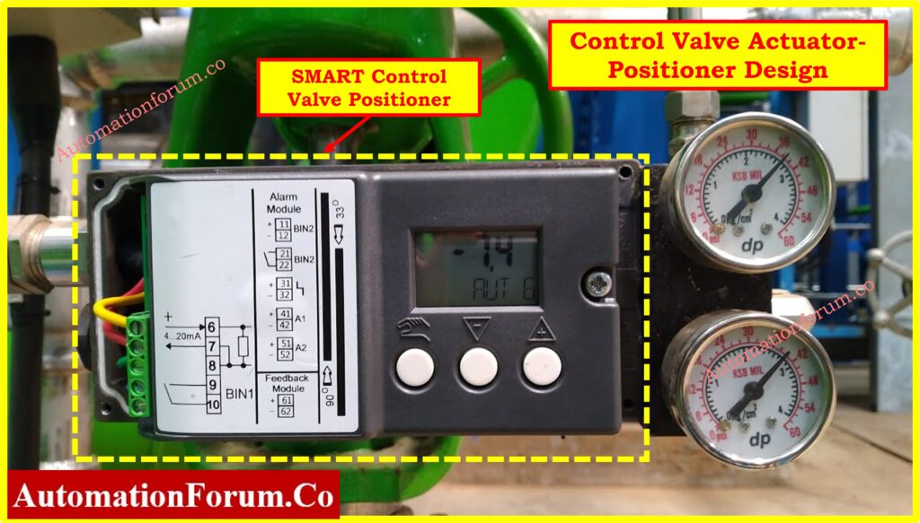
Air consumption of the valve assembly depends on the integration of both actuator and positioner components. Positioners built for high-performance complete their tasks by using pneumatic relays which reduce both response time and steady-state air usage. The requirement of external boosters exists for large or high-friction actuators to achieve specified stroking speed performances. The development of modern positioner technology has allowed for better airflow management and superior diagnosis functions and additional safety through safety instrumented systems (SIS).
Step-by-Step: Faulty Control Valve Positioner Replacement Procedure with Checklist
Response Time
The control valve achieves position adjustment at a particular speed which represents its response time based on input signal variations. Process control becomes effective when this parameter reaches sufficient levels especially during operations that need rapid adjustments. The measurement of response time uses the T63 parameter to identify how long it takes for the valve to respond to an input signal change so it reaches 63% position of that response.
Response time breaks down into two separate parts:
- Dead time: The static delay between the initiation of the input signal and the first detectable movement of the valve.
- Dynamic time: Time required for the actuating movement from start to reach 63% valve position represents the dynamic time.
- To minimize process variability it is crucial to have quick valve responses toward minor input signal modifications less than 1%. A valve that shows fast responses to normal signal changes brings better control performance outcomes during regulatory control operations.
In-Depth Guide: Control Valves in Process Industries: A Collection of In-Depth Articles
Valve Trim
The valve trim includes all internal mechanisms in control valves that enable fluid flow throttling and complete shutdown. The valve trim system contains three principal components which consist of the closure member together with seat as well as stem. The flow characteristics together with the pressure drop as well as the shut-off capability of the valve are determined by its valve trim design.
Control valves with different designs such as globe and ball and butterfly types require specialized trim modifications for particular applications. The flow characteristics of globe valves match those of equal percentage values yet butterfly valves operate with a nonlinear behavior pattern. Process requirements guide the selection process of valve trim because the flow rate and pressure drop and fluid properties need consideration.
Dead Time
Dead time represents the duration between beginning a step input and detecting any system response. Dead time in temperature control mechanisms stems from the combined effect of deadband alongside friction together with the positioner design. The control loops might become unstable when dead time conditions become longer than the process time constant in fast processes.
Stable control requires a dead time duration which should not exceed the third of total valve response time. Fast control loops require control equipment selection that reduces both dead time and friction while providing high operational responsiveness. The dead time must maintain similar values when opening or closing the valve system to prevent difficult loop tuning outcomes.
Gain
Guidance represents the numerical relation between the control valve’s output variation size to the source signal variation size. . It has two components:
- Static gain: The steady-state relationship between the input and output.
- Dynamic gain: Dynamic gain describes the input-output relation during motion fluctuations based on the input frequency rates.
Understanding control valve reactions to input signal changes depends heavily on gain measurement as a critical variable. Fast response comes from high gain but the system can experience instability as a result. On the other hand, low gain produces slow system performance.
Hysteresis
Hysteresis refers to the dependence of a control valve’s position on its prior state. A valve shows different flow rates even at a fixed opening when opening it from closed rather than from open positions. The occurrence of hysteresis results from friction and mechanical backlash together with various other factors.
When hysteresis exceeds accepted limits the control system will start to alternate near its desired setpoint which results in unsatisfactory control outcomes. The minimization of hysteresis requires both high-quality components and proper maintenance of the valve assembly.
Inherent Characteristic
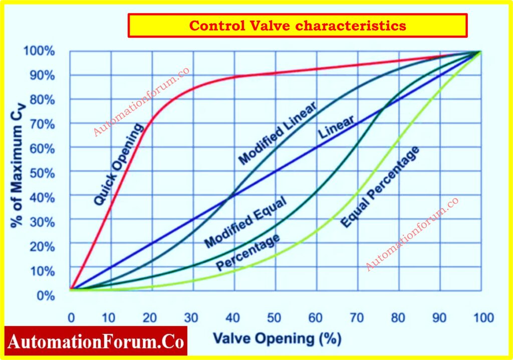
The inherent characteristic of a control valve describes the relationship between the flow coefficient (Cv) and the closure member’s travel. The inherent characteristic appears as a mapping between percent flow and percent travel in graphical format. The fundamental relationship between flow coefficient (Cv) and closure motion exists prior to any process conditions because it stems from valve trim construction methods.
Three common types of inherent characteristics can be found across control valves: linear, equal percentage and quick opening. Process needs along with control performance requirements determine which characteristic selection will become relevant.
Common valve characteristics:
- Linear – Flow increases proportionally with valve opening.
- Equal Percentage – Small openings provide fine control, while larger openings offer greater flow increase.
- Quick Opening – Rapid increase in flow at minimal openings, suitable for safety shut-off applications.
Shaft Wind-Up
During rotary valve operations shaft wind-up appears as the actuator portion of the shaft rotates before generating enough torque to pull past the valve end friction point. The twisting movement from shaft wind-up generates unnecessary time delay which increases valve deadband. Valves with extended shafts and high friction systems frequently demonstrate shaft wind-up behavior.
To mitigate shaft wind-up:
- Use high-strength shaft materials.
- Minimize friction at seal interfaces.
- Employ feedback correction in digital controllers.
Valve Capacity (Cv & Kv)
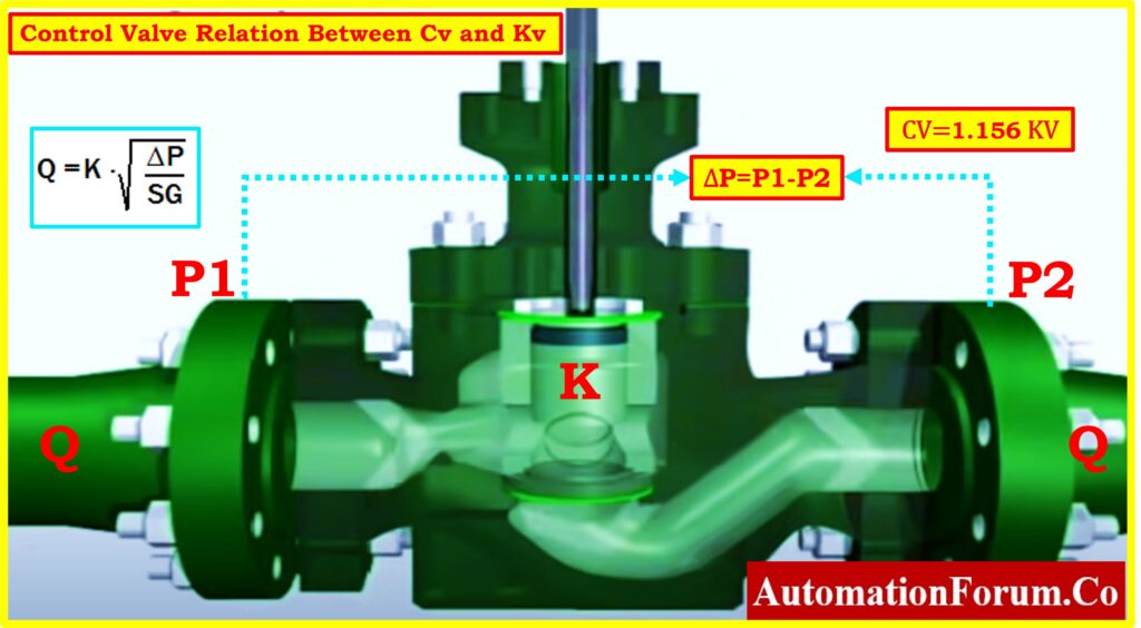
The flow capacity of control valves gets measured through flow coefficients known either as Cv or Kv. The flow coefficient determines exactly how much fluid the valve allows through under specific pressure changes.
- Cv is used in the United States and represents the number of U.S. gallons per minute of water at 60°F that flows through the valve with a 1 psi pressure drop.
- Kv is used internationally and represents the number of cubic meters per hour of water at 16°C that flows through the valve with a 1 bar pressure drop.
Handy Tool: Control valve Cv to Kv Conversion Calculator
Proper valve sizing remains essential because it determines whether the valve can manage the maximum flow rate anticipated within the process.
Understanding: Relationship Between Cv and Kv in Control Valves
Relative Flow Capacity
Relative flow capacity compares a valve’s flow coefficient (Cv) to the cross-sectional area of the pipe. The ratio of Cv to the square of the pipe diameter (d²) represents the standard expression of this measurement. The flow capacity parameter serves to determine which valve type between globe valves and butterfly valves provides better throttling performance levels.
For example:
- Globe valve – Lower Cv due to increased turbulence.
- Butterfly valve – Higher Cv due to streamlined flow.
Choosing a valve with an appropriate relative flow capacity ensures efficiency and process stability.
Fail-Safe Action
All control valves require a specific fail-safe position for protecting process safety upon loss of actuating energy. Common fail-safe actions include:
Fail positions depend on process safety requirements:
- Fail Close (Air to Open) – Valve closes upon failure (used in hazardous fluid handling).
- Fail Open (Air to Close) – Valve opens upon failure (for cooling water or emergency venting).
- Fail Lock – Valve remains in last position (used in certain process-critical applications).
Fail-safe action is achieved using spring-return actuators, auxiliary air reservoirs, or emergency shut-off systems.
The choice of fail-safe action depends on the process requirements and safety considerations.
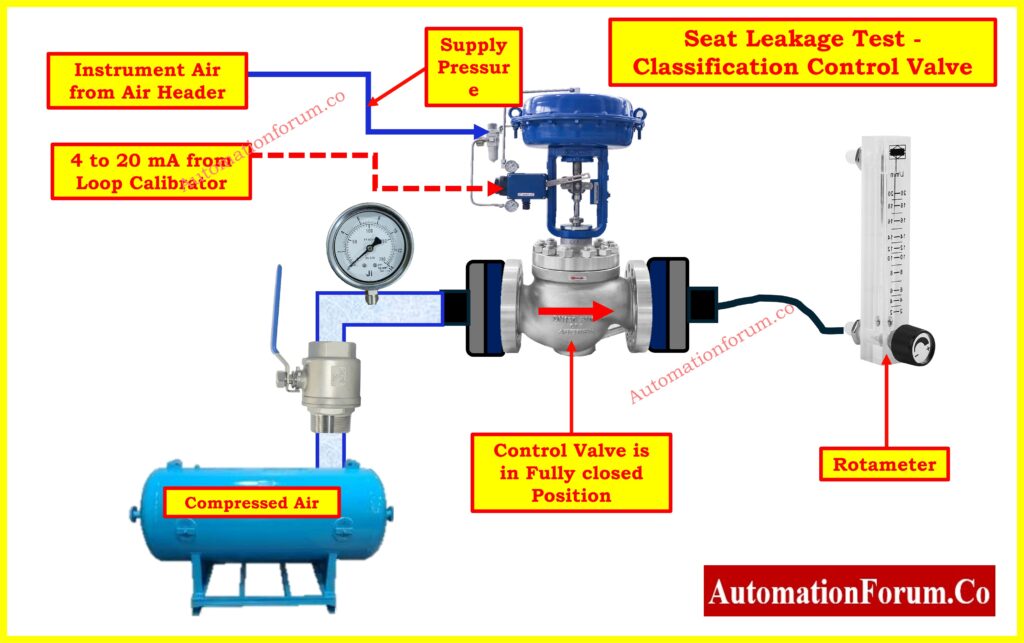
Valve Seat Leakage Class
Valve shut-off tightness is defined by the leakage class system. According to ANSI valve leakage is rated from Class I to Class VI and bubble-tight shut-off falls under Class VI. The measurement method for leakage calculates the valve capacity loss percentage under defined pressure conditions.
ANSI/FCI 70-2 specifies six leakage classes:
- Class I – No leakage testing.
- Class II – Low-leakage (0.5% capacity).
- Class III – Medium-leakage (0.1% capacity).
- Class IV – Moderate-leakage (0.01% capacity, metal seats).
- Class V – Very low-leakage (water-tight, precise applications).
- Class VI – Bubble-tight shutoff (soft-seated valves, zero visible leakage).
Selecting an appropriate leakage class ensures compliance with process requirements and minimizes losses.
Comprehensive: Control Valve Leakage Testing, Types, and Calculation Standards
Control valves function under static and dynamic parameters which encompass deadband and response time along with gain and hysteresis and flow capacity. The design parameters and their corresponding sizes and maintenance requirements function as critical elements to reduce process variability while both guaranteeing safety and maximizing process control. Engineers who study and modify these performance parameters can succeed in picking control valves which specifically satisfy their system requirements thus enhancing operational efficiency alongside system reliability and safety.
Must-Have: Top Essential Control Valve Calculators and Excel Tools for Instrumentation Engineers
Quiz on Control Valves and Actuators: Test your knowledge
Test your knowledge on control valve actuator troubleshooting! Identify faults, diagnose issues, and enhance your troubleshooting skills with this interactive quiz