- Step 1:Safety Considerations
- Step 2:Verify Control System and Interlocks
- Step 3:Control Loop Verification
- Step 4:Instrument and Wiring Inspection
- Step 5:Valve and Actuator Inspection
- Step 6:Control Loop Simulation and Tuning
- Step 7:Restart and Commissioning
- Step 8:Final Safety Check
- Comprehensive Checklist for Troubleshooting Control Valve in DCS Loop
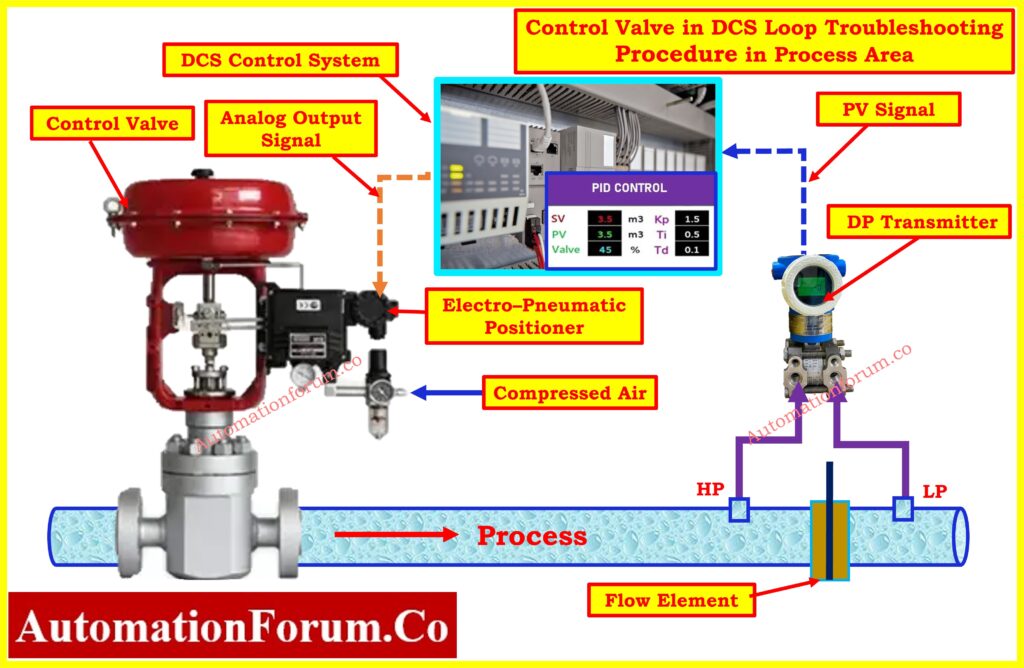
Control valves are critical components in process control loops, regulating the flow of fluids and maintaining process variables like pressure, temperature, and level within desired limits. When a control valve fails or operates inefficiently, it can cause process disruptions, safety hazards, and costly downtime.
This comprehensive troubleshooting checklist focuses on identifying, diagnosing, and rectifying issues in control valves connected to a Distributed Control System (DCS).
Step by Step Procedure for Troubleshooting Control Valve in DCS Loop at Process Area

Step 1:Safety Considerations
PPE (Personal Protective Equipment)
- Ensure that all personnel are wearing the appropriate PPE according to the site-specific safety standards.
- Double-check the PPE requirements, especially when working near hazardous chemicals, high temperatures, or pressurized equipment.
Obtaining the Work Permit
- Before performing any work, obtain the necessary work permits.
- These permits should detail the scope of the work, safety precautions, and personnel involved. Make sure all permits are signed and displayed in the work area.
Risk Assessment
- Conduct a hazard assessment to identify potential risks in the process area, including the presence of flammable gases, corrosive chemicals, or high-pressure systems.
- Discuss the potential risks with the team to ensure awareness of any dangers in the vicinity of the control valve.
Lockout/Tagout (LOTO)
- LOTO procedures must be followed to isolate energy sources, preventing accidental startup or release of hazardous energy.
- Electrical, pneumatic, and hydraulic supplies should be locked out and tagged to ensure no energy reaches the valve during troubleshooting.
- Verify that all points of isolation are effective before proceeding.
Control Valve Bypass Consideration
- If the control valve needs to be bypassed during troubleshooting, ensure that an alternate control method is available to maintain process stability and safety.
- Consult with operations staff to determine the best approach for bypassing the valve and minimizing process disruption.
- Document any bypass operations to ensure proper handover and process continuity.
Step 2:Verify Control System and Interlocks
Check Process Alarms and Interlocks
- Review the process alarms and interlock systems to identify any active conditions that may prevent the valve from operating correctly.
- Some control valves may be held in a fail-safe position by safety systems like the Emergency Shutdown (ESD) system or Safety Instrumented System (SIS).
- Investigate any active safety interlocks that could restrict valve movement, such as high-pressure cutoffs or flow limits.
Emergency Shutdown (ESD) and Safety Instrumented Systems (SIS) Loop
- If the control valve is part of a SIS or ESD, ensure that disabling the valve does not compromise process safety.
- These systems may keep the valve in a fail-safe position until the hazard is resolved. Special attention should be given when handling control valves within critical safety loops.
Bypass Status of the Valve
- Ensure that any bypass valves in the process are in their correct positions (open/closed) according to operating procedures.
- If bypassing the control valve is required for troubleshooting, obtain proper authorization from operations and safety personnel. Ensure that bypassing does not compromise the safety or stability of the process.
Step 3:Control Loop Verification
Verifying the control loop is very important in identifying whether the issue is with the valve, the controller, or the signal flow between them.
Verify Controller Output
- Check the output signal from the controller in the DCS. Control valves typically receive an analog signal, such as 4-20 mA, corresponding to the valve’s desired position.
- Ensure that the controller is providing the correct signal to the valve and that the signal is stable. This can be verified via the DCS interface or using a multimeter at the valve positioner terminals.
Control Logic and PID Parameters
- Review the control logic in the DCS to ensure it is functioning correctly. This includes checking for any errors in the programming, such as incorrect setpoints or interlock conditions.
- The PID tuning parameters (Proportional, Integral, Derivative) should also be checked to ensure they are properly tuned for the specific process conditions.
- Poorly tuned control loops can lead to oscillations, sluggish responses, or instability.
Inspect Control Valve Position
- Visually inspect the control valve’s physical position, ensuring it matches the position feedback in the DCS.
- Check for stiction or excessive play in the valve’s movement, as this can indicate mechanical issues such as a jammed actuator or worn valve stem.
- For accurate positioning, use valve position feedback devices, if available, to confirm proper alignment with the controller output.
Step 4:Instrument and Wiring Inspection

Wiring Inspection in Loop
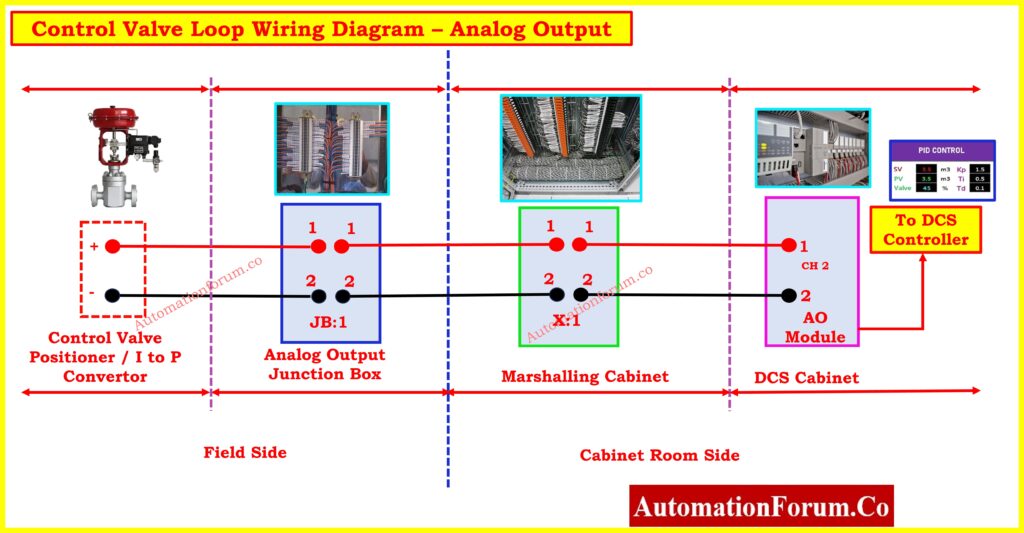
- Inspect the wiring from the DCS to the valve positioner. Verify that connections between the analog output card, marshalling panel, local junction box, and positioner are secure and free from damage.
- Look for signs of wear, corrosion, or moisture ingress, particularly in outdoor or high-humidity environments.
- A loose connection or damaged cable can cause intermittent signals, leading to erratic valve performance.
Local Junction Box and Marshalling Panel
- Examine the local junction box for proper wiring connections.
- Ensure that the signal wires are securely fastened and the junction box is properly sealed to prevent moisture ingress or contamination.
- Similarly, check the marshalling panel in the control room for loose or broken wires, and ensure that terminal blocks are secure and fuses are intact.
Analog Output Card
- The analog output card in the DCS rack is responsible for sending the control signal to the valve.
- Check the card for any signs of malfunction, such as output signal loss or irregular behavior.
- If necessary, replace or recalibrate the analog output card. Verify that all fuses associated with the card are in good working order.
Field Transmitter Accuracy
- Process transmitters (pressure, flow, temperature) feeding the control loop should be calibrated and providing accurate data.
- Verify that the measurements from these transmitters align with known process conditions.
- A faulty transmitter may provide incorrect feedback to the control loop, causing the control valve to react inappropriately.
Click here for Different Types of Instrument Calibration Procedures
Step 5:Valve and Actuator Inspection
Check the Pneumatic/Electrical Supply
- For pneumatic actuators, ensure that the air supply pressure is adequate as per the datasheet, free of leaks, and clean (filtered).
- For electrical actuators, verify that the correct voltage is being supplied and that there are no power interruptions.
- Inspect any supply lines for leaks, blockages, or loose connections that could affect the actuator’s performance.
Actuator Performance
- Manually operate the valve (if possible) to confirm the actuator’s functionality throughout its full stroke.
- Watch for slow movement, jerking, or any noise from the actuator that might indicate internal issues.
- Problems with the actuator’s internal components, such as worn seals, pistons, or diaphragms, can affect valve performance.
Positioner Calibration
- Control valve positioners convert the control signal (e.g., 4-20 mA) into mechanical motion.
- Verify that the positioner is properly calibrated and correctly translating the signal into valve position changes.
- Check for any drift in position feedback. If necessary, recalibrate the positioner according to the manufacturer’s guidelines.
Click here for Step by Step Calibration of Control Valve Positioner
Valve Accessories (I/P Converters, Solenoids)
- Inspect any I/P converters, which transform the electrical signal into a pneumatic signal.
- Ensure that the converter is operating correctly and delivering the correct output pressure to the actuator.
- Solenoid valves should also be checked for proper functionality, ensuring they respond to control commands and change the valve’s state as required.
Click here for Checklist for Conducting a Running Inspection of a Control Valve in a Process Area
Step 6:Control Loop Simulation and Tuning
Test Control Response
- Simulate changes in the control loop’s setpoint to test the response of the control valve.
- Watch the behavior of the process variable (e.g., flow, pressure, temperature) and observe the valve’s response.
- The valve should adjust smoothly to meet the new setpoint. Check for abnormal behavior, such as overshooting, oscillations, or sluggish responses.
Historical Data Evaluation
- Use historical data from the DCS to look for trends in the control loop’s performance.
- Check for issues like oscillations, excessive dead time, or drift in the process variable.
- These signs may indicate control loop tuning problems, mechanical issues with the valve, or problems with the process dynamics.
PID Tuning Parameters
- Adjust PID parameters if the control loop exhibits oscillations, slow responses, or poor tracking of the setpoint.
- Modify the Proportional (P), Integral (I), and Derivative (D) settings based on the loop’s performance. PID tuning should be carried out carefully, ensuring that process stability is maintained.
Step 7:Restart and Commissioning
Restore Interlocks and Bypass
- Once the issue has been resolved, ensure that any bypasses or overrides applied during troubleshooting are removed.
- Reactivate interlocks, alarms, and safety systems (SIS, ESD) to ensure normal process safety is restored.
Functional Testing
- Test the control loop and valve under normal operating conditions. Verify that the valve responds accurately to process changes and that control stability is achieved.
- Ensure the valve modulates smoothly, without abnormal noise, vibration, or delays in response.
Step 8:Final Safety Check
Verify System Integrity
- Ensure that all safety systems, such as interlocks, bypass valves, ESD, and SIS, have been restored to normal operation.
- Conduct a final safety walkthrough, verifying that all tools, lockouts, and safety measures have been removed, and the area is safe for regular operations.
- Close the work permit. Verify the performance of the control valve in normal operating conditions.
Documentation/Log Report
- Record all troubleshooting steps, including any corrective actions taken, parts replaced, and test results.
- This documentation will serve as a reference for future maintenance and troubleshooting activities.
Click here for Control Valves in Process Industries: A Collection of In-Depth Articles
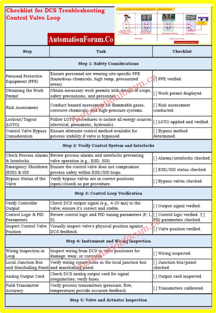
Comprehensive Checklist for Troubleshooting Control Valve in DCS Loop
This checklist provides a systematic guide to troubleshoot control valves in DCS loops, ensuring efficient diagnosis, safety compliance, and optimal performance in process control systems.

Refer the below link for the downloading of excel Checklist for Troubleshooting Control Valve in DCS Loop


