- What is Control Valve Positioner?
- 7 Steps Calibration Procedure for Control Valve Positioner
- Step 1: Tools Required for Control Valve Positioner Calibration
- Step 2: Safety Precautions
- Step 3: Prepare Calibration Setup for Control Valve Pneumatic Positioner
- Step 4 : Calibration of Control Valve Pneumatic Positioner
- Step 5: Recording Calibration of Positioner with Linearity Checks
- Step 6: Completion of Calibration
- Step 7: Calibration Report Preparation
- Calibration Procedure: Aligned with NIST and ISO Standards
What is Control Valve Positioner?
- In a typical system, the actuator receives a signal from the process controller and moves the valve as a result. This system functions, but it can be sluggish and actuators are only precise to a certain extent because they always have a certain offset.
- To achieve prompt, precise responses, something more is necessary in situations where accuracy or frequent changes are needed. A valve positioner is that additional component.
- A valve positioner is an apparatus that communicates with the actuator and process controller and is attached to the valve stem to sense the precise position of the valve. The process controller sends a signal to the positioner, which then sends a signal to the actuator to move the valve.
7 Steps Calibration Procedure for Control Valve Positioner
This below Step by Step calibration procedure provides a thorough explanation of how to calibrate a control valve positioner using reference standards.
Step 1: Tools Required for Control Valve Positioner Calibration

- Instrument air supply
- Precision Standard air pressure regulator.
- Tubes and standard fittings .
- Necessary hand tools.
- Reference standard pressure gauge for measuring pneumatic input signal 3 to 15 psi signal and supply air pressure.
- Soft Cloth for cleaning.
Step 2: Safety Precautions
- Please see the link below for further information on fundamental safety, general principles, and calibration operations in process industries. Calibration Process for Process Industries: Basic Safety and General Considerations
- In HMI, ask the DCS/SCADA panel operator how to set the controller or control loop to manual mode, and MOS (Maintenance Override Switch) for the ESD loop.
- Locate the Control valve with positioner that has to be calibrated. Verify to ensure that it is the correct control valve and write down any essential information Tag number (e.g., the manufacturer, model number, working range, etc.).
- Disable the power supply to the control valve, such as the position feed back transmitter and the fail safe SOV.
- Check that the power is switched off at the source of any nearby junction boxes or marshalling panels near the control room using an instrument loop diagram.
- The control valve’s pneumatic connections should be removed. This can involve opening clamps or removing fittings, depending on the kind of connection. Be careful not to harm any fittings or tubing.
- By locating the instrument air header in the control valve’s pneumatic circuit, it is possible to isolate the source of the instrument air supply.
- Keep in mind that based on the specific equipment and process location, this common procedure may need to be modified. While working with control valves or other process equipment, always adhere to any manufacturer’s instructions for the control valve positioner and local safety standards.
- Keep in mind any lockout/tagout requirements to avoid an unintentional start. Ensure that the control valve is kept out of the process.
Step 3: Prepare Calibration Setup for Control Valve Pneumatic Positioner

- Equipment for calibrating control valve positioners must be kept away from electromagnetic interference and vibrations. Also, the space has to be well-ventilated and illuminated.
- Gather all the necessary tools and equipment for the control valve positioner.
- As shown in the picture, install the temporary tubing between the following locations.
- Tubing should be installed between the control valve actuator and the output of the positioner. A standard pressure gauge should also be installed between the two components using a tee connection.
- Install the tubing for the positioner’s 3-15 psi signal input port from the instrument air supply through the precise standard air pressure regulator. Also, install the standard pressure gauge between these two components using a tee connection.
- Install the tubing for the 20 psi supply input port of the positioner from the instrument air supply through the standard air pressure regulator. At the same time, install the standard pressure gauge between these two components using a tee connection.
- Make sure that the connections are secure and that there are no leaks by checking them against the schematic that was provided for the calibration set up.
Step 4 : Calibration of Control Valve Pneumatic Positioner
Before beginning work on the calibrating valve positioners, the following method for beam alignment of valve positioner must be completed.
1. Beam Alignment of Valve Positioner

Beam alignment makes ensuring that components are in the proper mechanical positions so that the valve positioner may be calibrated. Provide the right amount of supply pressure. Also, provide the positioner an input signal that may be manually placed at the middle of the required input signal range.

See the figure for a position of each part. Use a screwdriver in the slot of the flapper setting adjustment or adjust the flapper assembly manually to various settings on the beam assembly.
2. Steps to Leveling the Beam are as Follows:

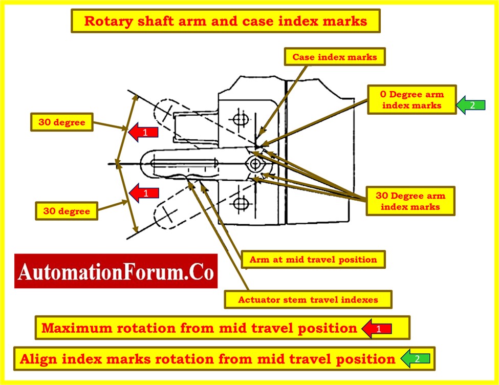
- Use a hand wheel or manual loader to move the control valve actuator to the middle of its range. See the figure. Raise the rotating shaft arm to line the case index marks with the 0° index markers on the rotary shaft arm as indicated in above figures. Place the travel pin in this position so that it is parallel to the arm and lines up with the rotary shaft arm’s corresponding total actuator travel index mark. The cap nut should be tightened.
- Turn the nozzle anticlockwise to the lowest setting after loosening the nozzle locknut. After around 4 anticlockwise rotations, extract the nozzle, and tighten the locknut.
- Eliminate any loading pressure and/or deactivate any hand wheels being utilized to move the actuator. The required tubing must be connected between the actuator pressure connection and the valve positioner output.

- Set the input signal value to midrange and connect the input to the valve positioner. For instance, set the input signal for a valve positioner with a 0.2 to 1.0 bar (3 to 15 psig) range at 0.6 bar (9 psig). The valve positioner should then be applied to supply pressure.
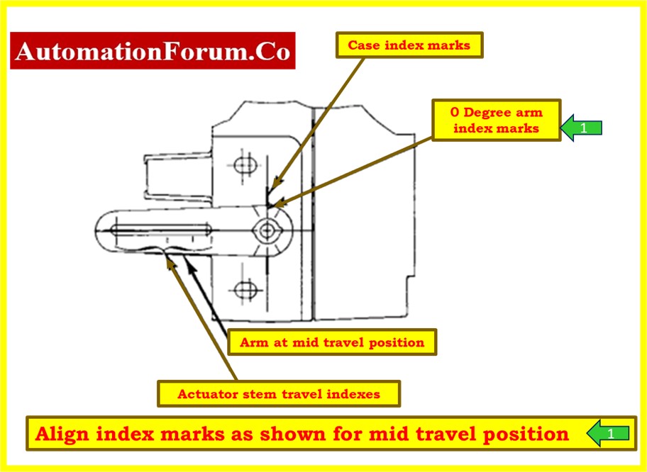
- Set the beam scale for the flapper assembly to zero. As indicated in above pictures, the rotary shaft arm’s 0° index marks should line up with the case index marks. If not, remove the locknut on the flapper assembly screw and adjust it until the case index marks and the rotary shaft arm’s 0-degree index marks line up. Locknut should be tightened.

- Position the flapper assembly at position 10 on the beam scale for direct acting. The case index marks and the 0° index markers on the rotary shaft arm should line up as indicated in the above figures. If not, unfasten the locknut on the bellows assembly and adjust the bellows pivot pin until the case index marks and the rotary shaft arm’s 0-degree index marks line up. Locknut should be tightened.
- Place the flapper assembly in position 10 on the reverse-acting side of the beam by moving it to the left. As indicated in above pictures, the rotary shaft arm’s 0° index marks should line up with the case index marks. If not, unfasten the locknut on the beam pivot pin and adjust the beam pivot pin until the case index marks and the rotary shaft arm’s 0-degree index marks line up. Locknut should be tightened.
- Repeat the previous three steps to improve alignment. Make sure the flapper reaches the nozzle squarely by checking again. If not, relevel the beam and adjust the nozzle. The valve positioner is prepared for calibration after alignment.
3. Calibration
- Close the valve positioner’s supply pressure. The required tubing from the actuator supply connection to the valve positioner output must be connected or reconnected. Set the input signal value to midrange and connect the input to the valve positioner.

- Apply supply pressure to the valve positioner and move the flapper assembly to roughly position 6 in the correct operating quadrant of the beam (direct or reverse acting). The actuator should be at its mid travel position, and the 0 degree index marks on the rotary shaft arm should line up with the case index marks as shown in the previous pictures. If not, start by looking for a loose linkage or an incorrectly installed cam. To make the desired input signal value match to the starting point of travel, a slight adjustment to the nozzle height could be required.
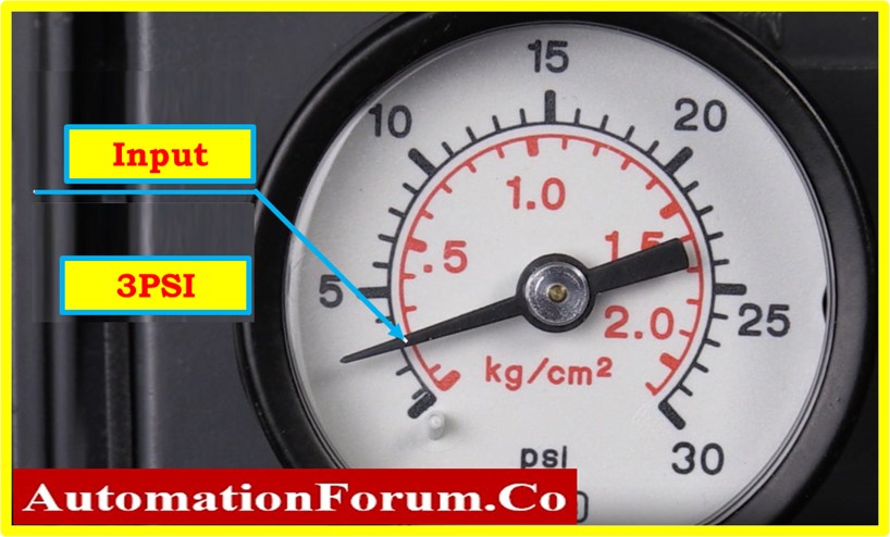
- Apply an input signal with a low value that falls inside the input signal range. Set the input signal, for instance, at 0.2 bar for a valve positioner with a range of 0.2 to 1.0 bar (3 to 15 psig) (3 psig). In order to get the actuator to the right end of its motion, loosen the nozzle locknut and adjust the nozzle. The only purpose of changing the nozzle location is to set the zero trim. The zero reference point is adjusted whenever the nozzle position is adjusted.

- Use an input signal that is equal to the maximum value permitted by the input signal range, and then watch the actuator stem movement. If the stem travel falls short of the intended range, move the flapper assembly to a higher number on the beam. If the input signal does not reach the maximum value of the input signal range before the necessary stem travel occurs, move the flapper assembly towards a lower number on the beam to shorten the stem travel.


- Repeat the last two steps until the intended travel is reached. Each time the location of the flapper assembly is altered in the last step, the procedure must be repeated to ensure appropriate zero.
- Bringing the flapper assembly closer to zero on the beam scale reduces stem travel.
- When properly calibrated, the positioner will fully vent or pressurize the actuator to supply pressure at the endpoints of actuator travel. Inaccurate positioner calibration may result in decreased seat loading.
- After the control valve positioner calibration is complete, normalize all connections and perform the control valve calibration.
- Go to the link below for a thorough explanation of the calibration process for control valves with positioners and stroke checking of control valve.
Step 5: Recording Calibration of Positioner with Linearity Checks
- Check the control valve’s stroking by performing linearity tests in the upscale and downscale directions at 0%, 25%, 50%, 75%, and 100%.
- Calibration is needed if the output value does not fall within the allowed range for stroking. And again, a control valve needs to be serviced or replaced if the output values have deviated from the permissible range.
- Go to the link below for assistance with troubleshooting control valves if you are experiencing any issues.
- In the event that all output values (+/- %) fall within acceptable bounds, no additional calibration is needed.
- The output data should be recorded into the calibration report’s as found/as left column.
Click here for Troubleshooting of struck Control valve
Step 6: Completion of Calibration
- Attach the calibration label to the control valve once the calibration has been successfully completed.
- After the calibration is finished, clean the device, store it safely, and note the calibration data for later use.
- Disconnect the pressure gauge, regulators, and other devices from the control valve.
- The processing area’s control valve connections should be reinstalled.
- Ensure that the workspace is clean.
- De-isolate the equipment.
- If the signal is bypassed or inhibited in control loop , return it to its normal level.
- Bring the control valve back into service and double-check that it is working properly.
Step 7: Calibration Report Preparation
The following picture shows how a control valve calibration sample report was made in the field or in a workshop using a pressure regulator and a standard pressure gauge as a reference.
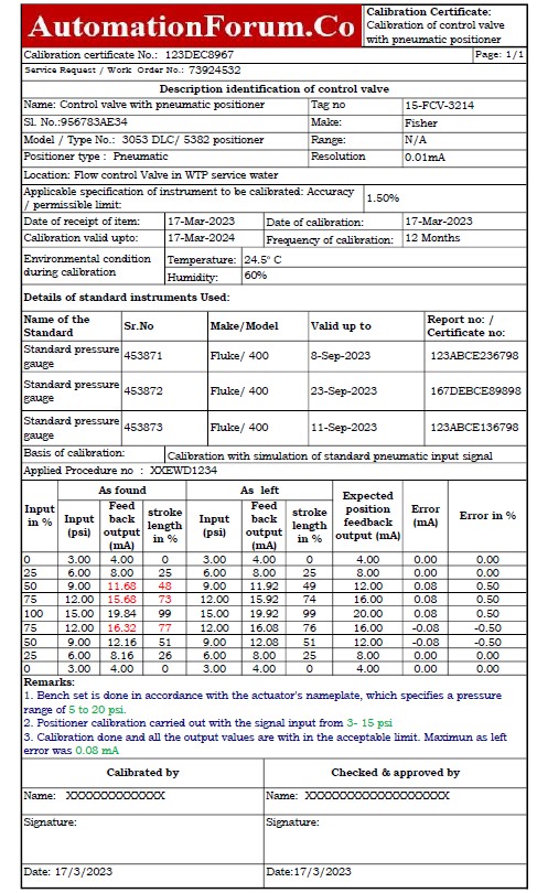
The link below will allow you to download the Excel template that was used to create the calibration report for the control valve with positioner.
Calibration Procedure: Aligned with NIST and ISO Standards
Ensuring reliable and accurate calibration of control valve positioners is crucial for achieving maximum efficiency and safety in industrial environments. Our calibration process is carefully developed to comply with the exacting specifications outlined in the NIST and IEC 61508 standards, ensuring precision and compliance with safety guidelines. Make ensuring that ISO 9001 or additional relevant quality management standards are followed.