What does a conductivity transmitter do?
Analytical transmitters developed for detecting electrical conductivity levels inside a particular solution for the purpose of industrial process monitoring, pharmaceutical production monitoring, and water quality monitoring are referred to as conductivity transmitters.
- What is the unit of conductivity transmitter?
- How do you calibrate a conductivity transmitter?
- Purpose and Scope:
- Tools required for conductivity transmitter calibration:
- Safety
- Calibration Setup
- Calibration principle
- Calibration procedure
- How do you clean conductivity cells?
- Temperature calibration of electrode
- Air calibration
- Calibration with Standard Solution
- Calibration by verification with standard reference conductivity meter
- Recording calibration
- Completion of calibration
- Sample conductivity transmitter report
Industry applications for conductivity sensors and transmitters include those in the food and beverage, chemical, life sciences, pharmaceutical, water, and power sectors. The application and conductivity range influence the choice of sensor. Select conductive sensors to detect low conductivities in pure and ultrapure water.
What is the unit of conductivity transmitter?
The ability of ions in an aqueous solution to conduct an electrical current is measured using conductivity Transmitter. MilliSiemens/cm (mS/cm) and microSiemens/cm (?S/cm) are the fundamental measuring units since the ranges in aqueous solutions are often tiny.
How do you calibrate a conductivity transmitter?
Purpose and Scope:
This procedure provides a thorough description of how to calibrate a conductivity transmitter using common reference solutions in the process area or analyzer room.
Tools required for conductivity transmitter calibration:

- Necessary hand tools.
- Multimeter with mA option
- Reference conductivity solution.
- Standard conductivity sensor
- Standard temperature sensor
- Beaker.
- Soft tissue paper for cleaning sensor
- Soft Cloth for cleaning.
- Reference manual
Safety
- For information on fundamental safety, general principles, and calibration operations in process industries, check out the link given below.
- Request that the operator of the SCADA/DCS panel configure the controller in manual mode for the conductivity transmitter control loop and MOS for the ESD loop.
- Find the conductivity transmitter you want to calibrate, double-check that it is the correct conductivity transmitter, and make a note of any important details, such as the tag number (for example, tag number, the manufacturer, model number, conductivity range, etc.).
- Switch off the power supply to the conductivity transmitter. Make sure that any nearby junction boxes in the analyzer room or marshalling panels close to the control room have their power sources turned off.(For instance, shut off the circuit breaker or unhook the cables).
- Keep in mind that depending on the particular conductivity transmitter and calibration place, this basic method may need to be modified. When working with conductivity transmitters or other process equipment, always adhere to any manufacturer’s instructions and local safety standards.
- In order to avoid an unauthorized start-up or usage of the conductivity transmitter, adhere to the necessary lockout/tagout protocols. Take care to keep the conductivity transmitter out of the way of the operation.
Calibration Setup

- The location of the calibration equipment must be free from electromagnetic interference and vibrations. The area must also be well-lit and ventilated.
- Collect all the tools, references, and materials needed for the conductivity transmitter calibration.
- Use an instrument loop diagram and probes to create a series-connected analogue input loop to the multimeter (mA mode) between the junction box and the conductivity transmitter.
- The connections have been carried out and are currently being prepared for the conductivity transmitter’s calibration, as shown in the diagram.
Calibration principle
In order to achieve accurate measurements, an online conductivity transmitter’s calibration principle entails comparing the transmitter’s data to known conductivity values. The concentration of ions in the solution affects conductivity, a measurement of a solution’s capacity to carry electrical current.
By adapting the process sample to the readings obtained from an independent conductivity analyzer (portable standard conductivity tester), calibration may also be carried out. To ensure its accuracy in this situation, the portable standard conductivity tester should undergo traceable periodic calibrations. Additionally, in order to avoid any potential mistake caused by the temperature compensation circuitry of the instrument, the calibration of the process loop using the portable standard conductivity meter must be performed at the same temperature.
Calibration procedure
- Check that the sample tubing and wire connections on the conductivity transmitter and sensor electrode are stable.
- Turn on the power supply, and then take off the conductivity transmitter terminal cover to make sure there is a power source present.
- The instrument data sheet can be used to confirm a number of the parameters. The tag number, the LRV, and the URV are common characteristics of conductivity transmitters.
How do you clean conductivity cells?
- Remove the sensor electrode from the sample line after closing the sample isolation valve.
- Stains on the electrode might negatively affect the cell constant, making it difficult to measure conductivity accurately.
- In order to eliminate stains, rinse the electrode in clean water (such as tap water) after the measurement.
- Even if staining is not visible, the sensor’s performance could have changed.
- If so, wash the electrode by swiping the sensor up and down in water that has a little amount of neutral detergent dissolved in it or hydrochloric acid (approximately 0.1 mol/l).
- If the electrodes on pure-water sensors are challenging to clean, gently wipe them from top to bottom using a cotton wool swab. Rinse the electrode with water after cleaning it.
Temperature calibration of electrode
- It is crucial to have a precise temperature measurement in order to produce the most accurate readings.
- This has an impact on both the output signal (when utilized) and the temperature display. But the precision of the calibration and temperature correction are more crucial.
- A high precision thermometer should be used to measure the sensor system’s temperature independently.

- The value of “Measured temperature” should be adjusted to agree with the reading after measuring the sample temperature using a high precision thermometer (zero offset calibration only).
- This should be carried out as closely as possible to the normal operating temperature for the optimum accuracy.
Air calibration
- General air calibration of the transmitter electrode cell is not required until a lengthy wire with a low conductivity has to be monitored.
- The conductivity transmitter measurement should be zero with the clean, dry cell outside.
- The electrode’s air calibration corrects for excessive cable capacitance and provides higher accuracy at low values.
- When a sensor is installed or changed, this should be done.
- A dirty sensor may possibly exhibit a significant zero offset after some time in use due to fouling. Clean the sensor, then retry.
- Additionally, there should be no electromagnetic interference present while doing an air calibration.
- Perform the air calibration of the electrode according to the order specified above.
- If the value is not showing zero, make the adjustment using the transmitter’s instructions.
Calibration with Standard Solution
- Select standard solutions with conductivity values that are within the range of the conductivity transmitter’s measurement capabilities.
- Follow the manufacturer’s instructions for preparing the standard solutions, ensuring that they are properly mixed and at the correct temperature.
- Obtain the appropriate calibration standards and solutions for the online conductivity transmitter. These may include reference solutions with known conductivity values and temperature-compensated calibration standards.
- The standard solutions can irritate the skin and eyes, and if swallowed or inhaled, they raise the risk of harm. Always wear gloves, and safety eyewear when handling solutions.
- All standard solutions must be used in accordance with the MATERIAL SAFETY DATA SHEET (MSDS), and copies of the MSDS should be kept in the workspaces.
- Completely rinse the sensor with water.
- Take one beaker, and fill it with the prepared standard solution.
- Before submerging the sensor in standard solution, thoroughly clean the electrodes of any washing water.
- Immerse the transmitter electrode in the beaker of standard solution.

- A reference standard temperature sensor should also be placed in the beaker to measure the standard solution’s temperature.
- Wait until the output mA and indication on the transmitter’s display are stable together with the measured value in the reference temperature sensor.

- Determine the value of the standard solution’s conductivity by comparing the standard thermometer’s measured temperature reading of the solution with the solution’s temperature compensation table.
- After determining the value of the standard solution conductivity value, adjust the transmitter display reading and the corresponding mA output shown by the multimeter in the transmitter output.
- Adjust the transmitter display reading and the matching mA output indicated by the multimeter in the transmitter output with the determined value of the standard solution conductivity value.
- Verify the accuracy of the transmitter by applying a standard solution with a different conductivity level and ensuring that the transmitter accurately reads the conductivity.
- If possible, use a reference solution with a different conductivity level and make sure the transmitter properly reads the conductivity to verify the accuracy of the transmitter.
- Repeat the calibration process as necessary to calibrate the conductivity transmitter to the specified tolerance.
Calibration by verification with standard reference conductivity meter
- Clean and reinstall the conductivity measurement probe in the sampling pipe line, and then open the sample isolation valve.
- Collect the process sample from the conductivity transmitter output after the sample flow is regular and free of air bubbles.
- Then use a standard reference conductivity meter to measure the collected sample.
- With a portable standard reference conductivity meter, compare the value displayed by the conductivity transmitter.
- Both indicators should have the same value. If not, make adjustments to the conductivity transmitter.
- Additionally, in order to avoid any potential mistake caused by the temperature compensation circuitry of the instrument, the calibration of the process loop using the portable standard conductivity meter must be performed at the same temperature.
- Additionally, the calibration of the process loop using the portable standard conductivity meter must be carried out at the same temperature in order to prevent any potential error brought on by the temperature compensation circuitry of the instrument.
Recording calibration
- To ensure that the conductivity transmitter is generating the right results, check its linearity.
- Recalibration is necessary if the conductivity transmitter output reading value does not fall within an acceptable range. Once more, a conductivity transmitter electrode has to be fixed or changed if the output values have deviated from the permitted range.
- If every output result (+/-%) falls within acceptable bounds, no additional calibration of the conductivity transmitter is necessary.
- The blank calibration report with conductivity electrode data should include the output values from the conductivity transmitter written in the as found/as left column.
Completion of calibration
- Attach the calibration label on the Conductivity transmitter once the calibration has been completed successfully.
- Clean the Conductivity transmitter, store it securely, and save the calibration data for later use when the calibration is finished.
- Remove all of the Conductivity standard solutions, and then discard any used ones in a responsible manner.
- Make sure the Conductivity transmitter’s calibration area is neat.
- De-isolate the Conductivity transmitter and take off any maintenance tags from it.
- Before resuming usage of the Conductivity transmitter, make sure it is functioning properly.
Sample conductivity transmitter report
The illustration below shows how the conductivity transmitter sample report of calibration was performed in the process area or analyzer room using reference standard conductivity solutions.
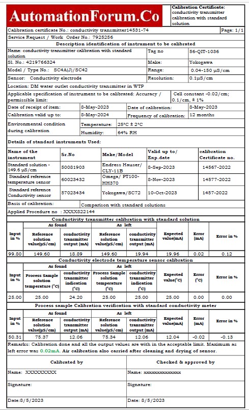
By selecting the link below, you can get the Excel document that was used to create the conductivity transmitter calibration report.