- 8 Steps Procedure to Calibrate Control Valve
- Step 1: Prepare the Tools required for control valve calibration
- Step 2: Safety Precautions
- Step 3 : Prepare the Setup for bench setting of control valve
- Step 4 : Verify the bench setting of control valve
- Step 4 : Prepare the Setup for calibration of control valve with positioner
- Step 5 : Calibration of Control Valve with Positioner
- Step 6: Recording Calibration
- Step 7: Completion of Calibration
- Step 8: Calibration Report Preparation
- Calibration Standards for Control Valves
8 Steps Procedure to Calibrate Control Valve
This below Step by Step control valve calibration procedure provides a thorough explanation of how to calibrate a control valve using reference standards.
Which instrument is used to calibrate control valve?
Step 1: Prepare the Tools required for control valve calibration

- Instrument air supply
- Precision Standard air pressure regulator.
- Tubes and standard fittings
- Reference standard pressure gauge for measuring pneumatic input signal 3 to 15 psi signal and monitor the bench set pressure.
- Multimeter with probe and leads
- Soft Cloth for cleaning.
Step 2: Safety Precautions
- Please click the link provided below for details on basic safety, general principles, and calibrating activities in process industries. Basic Safety and General Considerations for Process Industries Calibration Process
- Ask the panel operator how to set the controller or control loop to manual mode for the control loop in HMI and MOS for the ESD loop.
- Locate the Control valve you want to calibrate. Check to make sure it’s the right control valve, a control valve and record any pertinent information Tag number (e.g., the manufacturer, model number, working range, etc.).
- Disable the supply of power to the control valve, such as the position feedback transmitter and the fail safe SOV, and so on.
- Make sure the power supply is turned off at the source of any nearby junction boxes or marshalling panels close to the control room
- Depending on the kind of system, you may need to depressurize it before detaching the control valve. Use the right procedures to depressurize the system (e.g., vent the pressure or isolate the system).
- Carefully unhook the electrical connections from the control valve. Be sure to follow any necessary safety measures (such wearing insulated gloves or other protective gear) and take care not to damage the wires or connections.
- Remove the pneumatic connections for the control valve. Depending on the kind of connection, this may include releasing clamps or removing fittings. Take care not to damage any tubing or fittings.
- Keep in mind that this typical procedure may need to be modified depending on the specific equipment and process location. Always follow any manufacturer instructions and local safety regulations while interacting with control valves or other process equipment.
- Observe all necessary lockout/tagout procedures to prevent an unintended start. Make sure to keep the control valve away from the process.
Calibration Setup
Before beginning the calibration of the control valve, we need to make sure that the actuator bench setting has been verified.
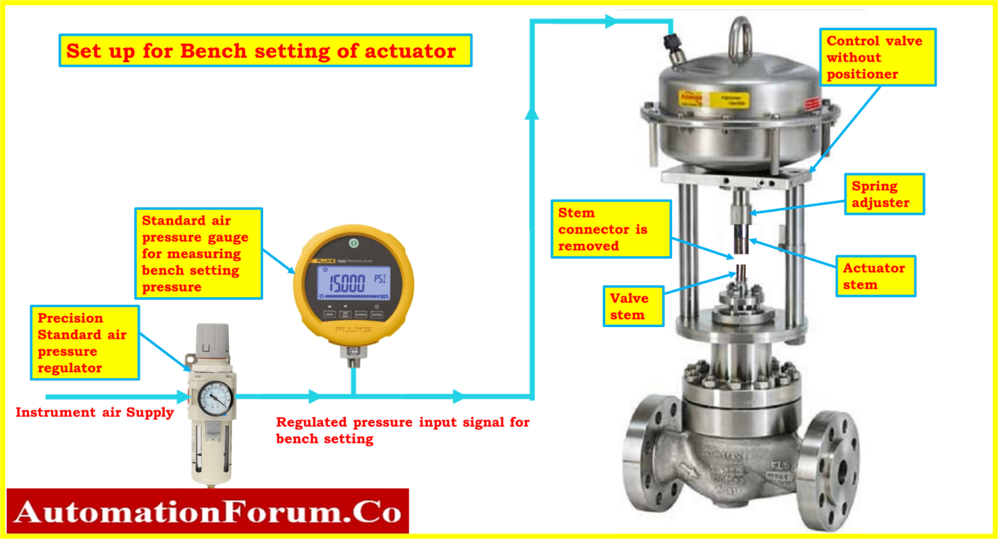
Step 3 : Prepare the Setup for bench setting of control valve
Step 4 : Verify the bench setting of control valve

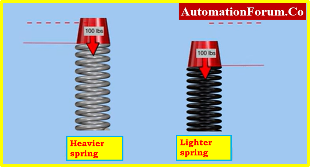
- Bench set is the term for the initial compression that a spring adjuster applies to the actuator spring.
- The lower bench set defines the force available and the pressure necessary to start the valve-opening movement for air-to-open valves.
- The lower bench set establishes the pressure necessary to start the valve-closing movement for air-to-close valves. Pressure applied less bench set less spring compression from travel determines seating force.
- The spring angle may vary somewhat as a result of spring tolerances.
- The bench set requires the most accuracy once the valve has been seated. For information on how to modify the spring, see the manufacturer’s instructions.
- The instrument air pressure needed to completely stroke the actuator over its entire range and to start moving the stem against its closure spring is known as an actuator bench-set.
- The spring compression is changed to compensate for the process pressures that will be applied on the plug region when these settings are made.
- Before the actuator is installed onto the valve and, this adjustment is normally made.
Bench setting procedure
- Anchor the actuator with a vice and load the actuator diaphragm temporarily.
- Valve positioner and stem connector need to be removed before starting the procedure.
- Provide a certified pressure gauge (PG) that can properly measure the diaphragm pressure from zero to the upper bench set pressure shown on the actuator name plate.
- Temporarily apply and alter actuator loading pressure using a pressure regulator.
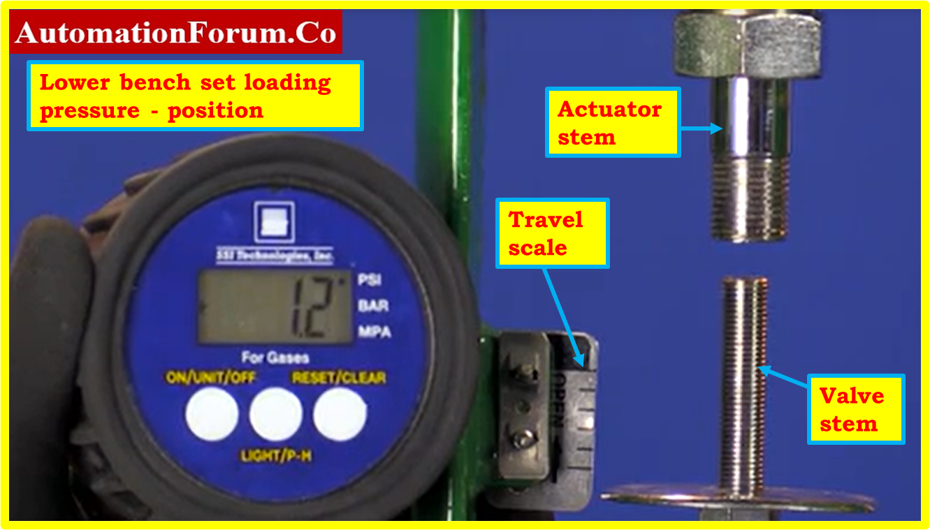
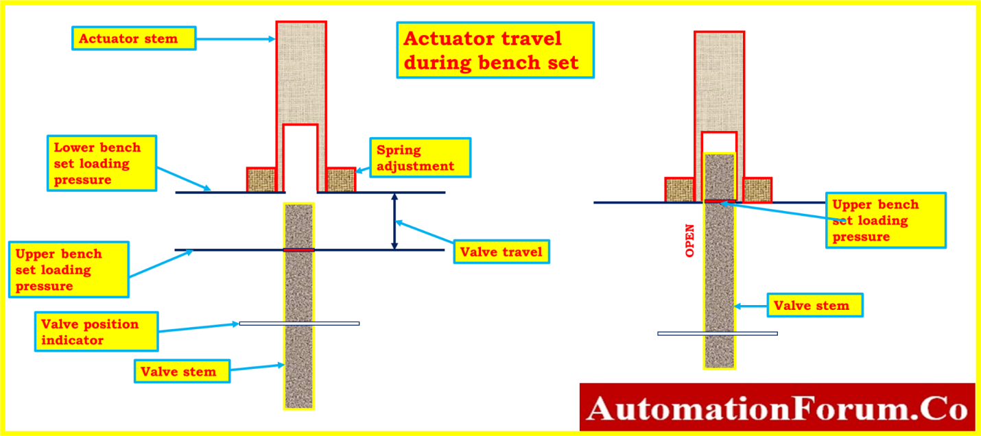
- Make that the actuator stem is positioned as shown in the above figure at the top of its travel. Diaphragm loading pressure should be set at 0 psig.
- Slowly increase the pressure from 0 psig to the lowest bench set pressure while monitoring for actuator stem movement.
- At the lower bench set pressure, the actuator stem should be moving.
- If movement is sensed either before or after the lower bench set pressure is attained, slide the spring adjuster into or out of the yoke until the actuator stem movement is first detected there.

- Make sure the spring adjuster is set to the stated specifications.
- Apply pressure on the diaphragm equal to the top bench set loading pressure. The actuator stem is extended towards the valve by this pressure.
- Keep in mind that, as indicated above, the actuator stem may move over the valve stem.
- Use a marker or cello tape to mark the valve stem at the actuator stem’s end.
- If the actuator stem does not pass over the valve stem, you must indicate this point of stem travel.
- Diaphragm loading pressure should be gradually reduced until the lowest bench set pressure is used.
- Measure the distance from the end of the actuator stem to the marking or tape on the valve stem.
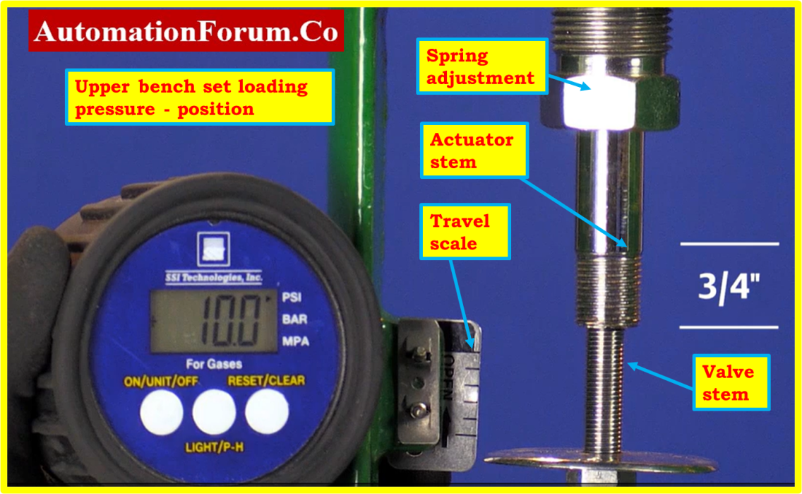
- The distance must be equal to the travel span shown on the scale of the travel indicator.
- Bench set adjustment is finished if the travel span is accurate. The valve and actuator may then be connected to one another with stem connector. Also the positioner need to be installed back.
- In the event that the span is not accurate, either the spring has been damaged in some way or the incorrect spring has been fitted on the valve actuator.
Step 4 : Prepare the Setup for calibration of control valve with positioner
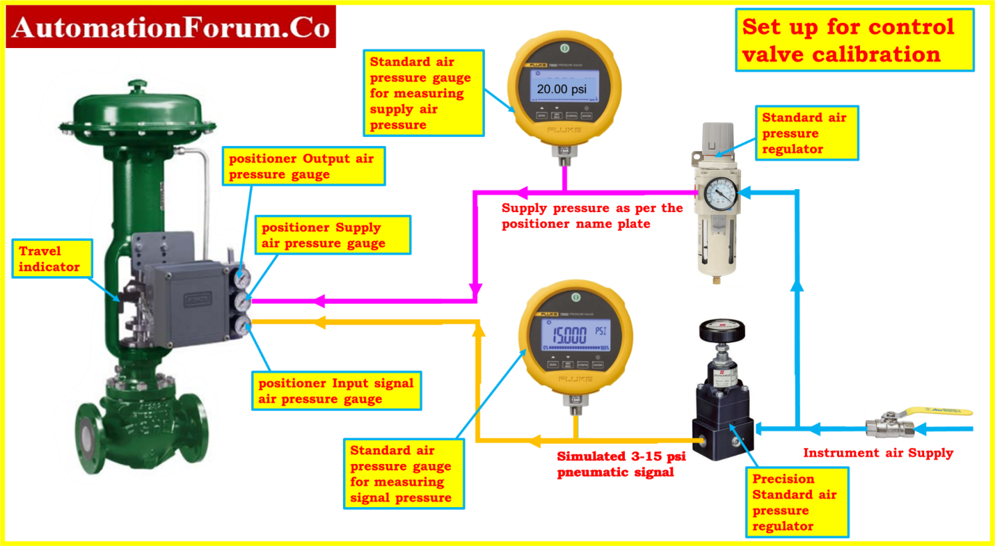
As shown by the connection diagram, connect the control valve and its calibration accessories.
Step 5 : Calibration of Control Valve with Positioner
The following process is for calibrating a control valve that is equipped with a pneumatic positioner.
- When the control valve bench set has been finished, the positioner should then be installed.
- In order to calibrate the automated control valve with a pneumatic Positioner, an air regulator is inserted and then set at an air supply of 20 PSI.
- Adjust the Regulator until the pressure meets the specifications shown in the datasheet for the positioner.
- For the purpose of simulating the signal pressure of 3-15 PSI, connect and utilize a fine precision regulator, which then delivers an opening/closing signal to the valve.
- When applying the 3 PSI signal, the valve must be at 0% of stroke length.
- If it is not entirely closed, you may modify the position of the valve using the zero adjustment in Positioner.
- When applying the 15 PSI signal, the valve must be at 100% of stroke length.
- If it is not entirely opened, you may modify the position of the valve using the span adjustment in Positioner.
- These procedures will be performed as many as required until the valve movement accurate values, i.e., open and close parameters.
- Typically, a position transmitter will be placed with the control valve. So, using the position transmitter’s feedback mA, the stroke length could be measured. It could have converted into valve movement in %
- The intermediate positions will be checked once the 0% and 100% percentages have been adjusted.
- You will need to perform the method of calibration as many times as necessary until the control valve is calibrated to the appropriate tolerance.
- Depending on the specific control valve positioner and kind of control valve being utilized, the calibration process may change. Please read the manufacturer’s instructions before starting, then.
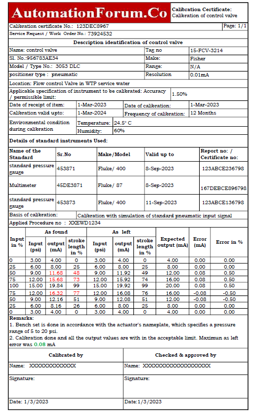
Step 6: Recording Calibration
- Do linearity tests in the upscale and downscale directions at 0%, 25%, 50%, 75%, and 100% to make sure the control valve is stroking appropriately.
- If the output value does not fall within stroking an acceptable range, calibration is required. Once again, if the output values have deviated from the permitted range, a control valve has to be serviced or replaced.
- No extra calibration is required if every output value (+/- %) falls within accepted limits.
- The output data should be entered into the as found/as left column of the blank calibration report.
Step 7: Completion of Calibration
- When the calibration has been successfully completed, attach the calibration label to the control valve.
- When the calibration is complete, clean the apparatus, store it somewhere safe, and record the calibration information for future use.
- Disconnect the regulators, pressure gauge, and other equipment.
- Reinstall the control valve in the processing area.
- Make sure the workplace is tidy.
- De-isolate the equipment.
- Restore the signal’s usual level once it has been bypassed or inhibited.
- Put the control valve back into use and check that it is operating normally once you have done so.
Step 8: Calibration Report Preparation
In the workshop using the information gathered during the calibration, prepare the calibration report. The following picture displays how the control valve calibration sample report was completed in the field or a workshop using a pressure regulator and a standard pressure gauge as the reference.
The Excel template that was used to make the control valve calibration report can be downloaded from the link below.
Calibration Standards for Control Valves
Standards and guidelines that offer suggestions and instructions for calibrating control valves. One commonly used standard is:
ISO 5208: General Principles for Control Valve Calibration:
Provides guidelines on test equipment, procedures, and reporting for control valve calibration.
IEC 60534: Calibration of Electropneumatic Positioners:
Specific to electropneumatic positioners, covering zero and span adjustments, hysteresis, and repeatability.
ASME B16.34: Dimensions for Flanged Butterfly Valves:
Focuses on face-to-face and end-to-end dimensions, crucial for calibrating butterfly valves.
ANSI/ISA-S75.19.01: Calibration of Control Valves in Process Industries:
Designed to the process industry, addressing test procedures, acceptance criteria, and reporting.
The calibration procedure for the control valve was developed based on reference from NIST standards, ensuring adherence to precise measurement principles and traceability to recognized calibration practices