- Introduction to Field vs Control Room Reading Mismatch
- What Is Loop Checking in Instrumentation
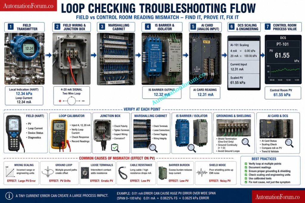
- Typical Loop Checking Workflow
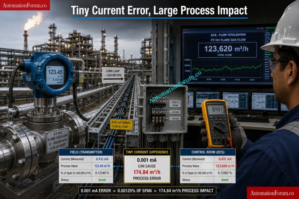
- Industrial Example of Flare Flow Meter Reading Mismatch
- Real Physics Behind Loop Current Deviation
- Most Common Causes of Field vs DCS Reading Mismatch
- Step by Step Troubleshooting Workflow: Field vs Control Room Reading Mismatch
- HART Communication vs Actual Loop Current
- Practical Field Lessons Learned
- Best Practices to Avoid Field and DCS Reading Mismatch
- Loop Current Drop vs Process Value Error Table
- Key Takeaways: Why Loop Integrity Matters
- Frequently Asked Questions About Loop Checking and DCS Reading Mismatch
Introduction to Field vs Control Room Reading Mismatch
Why This Problem Happens in Process Industries
One of the most common commissioning and troubleshooting headaches in process plants is this simple but dangerous situation.
The field transmitter shows one value. The control room shows another. The loop check team starts questioning the transmitter, the DCS, the cable, the AI card, and even the calibration certificate.
Why Small Current Errors Create Large Process Value Errors
In reality, the problem is often much smaller than it looks, but the impact can be large. A tiny loop current deviation can create a noticeable process value error, especially in wide span applications such as flare flow, custody transfer, and high range level or flow measurement. This is why field vs DCS reading mismatch is one of the most searched and most misunderstood problems in 4 to 20 mA loop troubleshooting.
Why This Issue Is Common During Loop Checking
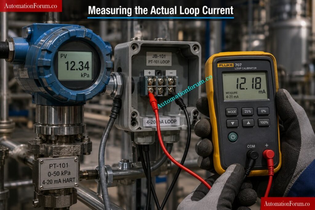
Most engineers overlook this simple fact: the transmitter display often shows the internal calculated value, while the control room depends on the actual received loop current. That means the transmitter can look healthy even when the loop itself is not perfect.
The result can be wrong flow reporting, false alarms, bad control actions, SIS voting problems, and process instability. During startup, shutdown, migration, transmitter replacement, or loop checking, this mismatch becomes even more visible.
Master Cold and Hot Loop Checking Before Startup Failures: Cold and Hot Loop Checking in Automation: Key Differences and Step-by-Step Procedures
What Is Loop Checking in Instrumentation
Difference Between Calibration and Loop Checking
Loop checking is the process of verifying that the complete instrument signal path works correctly from field device to control room indication.
It is much more than simple transmitter calibration.
Calibration verifies the accuracy of the instrument itself. Loop checking verifies the integrity of the entire measurement chain.
Components Involved in a Typical Instrument Loop
A typical industrial loop includes:
- Field transmitter
- Junction box
- Marshalling cabinet
- IS barriers or isolators
- Signal cables
- Analog input cards
- PLC or DCS scaling
- Engineering unit conversion
- HMI display
- Alarm configuration
Refer the below link for the Understanding Zener vs Galvanic Isolation in IS Loops for 4 to 20 mA Systems
Purpose of Loop Checking During Commissioning
During loop checking, engineers verify:
- Correct wiring
- Correct polarity
- Proper loop current
- Signal integrity
- Correct scaling
- Correct engineering units
- Alarm operation
- Controller response
- Interlock actions
- Historical trending
Even with modern digital communication systems, 4 to 20 mA loops still dominate process industries because they are simple, reliable, noise-resistant, and easy to troubleshoot.
Pressure Transmitter Loop Checking Method Every Technician Must Know: Method Statement for Loop Checking of Pressure Transmitter Loop
Typical Loop Checking Workflow
A typical commissioning workflow includes:
- Verify instrument installation
- Verify cable continuity
- Check insulation resistance
- Power the loop
- Simulate process values
- Measure loop current
- Verify DCS indication
- Check alarms and trips
- Validate interlocks
- Document loop results
Many engineers wrongly assume that if the transmitter display is correct, the DCS reading must also be correct. In reality, the control room only sees the current arriving at the analog input card.
Motor Operated Valve Loop Checking Without Missing Critical Faults: How to do loop checking of Motor operated valve?
Why Field and Control Room Readings Differ
This is the core engineering concept most technicians overlook.
How a Field Transmitter Calculates Process Value
- The transmitter display value comes from the internal processor calculation.
- The sensor measures pressure, flow, temperature, or level and converts it into a digital process value internally. The transmitter processor then generates the analog output current.
- The local display often shows the internally calculated value.
- Minor loop issues may not affect this displayed value.
Improve Signal Quality Fast Using This Powerful SNR Calculator: Signal-to-Noise Ratio (SNR) Calculator for Instrumentation and Control Systems
How DCS and PLC Calculate Process Value
- The DCS or PLC does not see the transmitter processor value directly.
- The analog input card only measures the received loop current.
- The AI card converts the received current into engineering units using scaling equations.
- If the current reaching the card changes slightly, the displayed process value changes accordingly.
Why HART Value and Analog Value Can Be Different
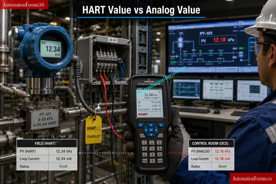
That means:
- Transmitter may show correct value
- HART communicator may show correct value
- DCS may still show incorrect value
because the analog current reaching the AI card is different.
IS Barrier Earth Fault Calculator That Prevents Dangerous Failures: IS Barrier Earth Fault Current Calculator | Intrinsic Safety Loop Design Tool
Industrial Example of Flare Flow Meter Reading Mismatch
Consider a flare flow meter with the following range:
- LRV = 0 kg/hr
- URV = 150,000 kg/hr
- Output = 4 to 20 mA
The field transmitter shows:
- 6.00 mA
- 18,750 kg/hr
However, actual measured loop current at the AI card is:
- 5.99 mA
The DCS calculates the process value using:
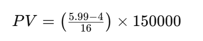
Substituting the values:
Final calculated value: 18,656.25 kg/hr
Difference: 93.75 kg/hr
Actual current deviation: Only 0.01 mA
Percentage error: Approximately 0.06%
This example shocks many engineers because the electrical deviation is extremely small while the process deviation becomes very large.
Wide-span transmitters amplify small loop current errors dramatically.
This is why flare systems, steam metering, LNG transfer, custody transfer, and high-capacity flow loops require extremely careful loop integrity verification.
Live 4-20mA Signal Verification Procedure Every Engineer Needs: Live Signal Verification 4 to 20 mA Loop Standard Operating Procedure (SOP)
Real Physics Behind Loop Current Deviation
Effect of Cable Resistance in Long Distance Loops
Theoretically, current should remain constant throughout a series loop.
But practical industrial conditions create measurable deviations.
Real plants introduce many non-ideal conditions:
- Cable resistance
- Long cable runs
- Loose terminals
- Rusted connections
- Moisture ingress
- Poor crimping
- Ground loops
- Shielding problems
- Electromagnetic interference
- Barrier loading
- Analog card burden
- Voltage drops
Convert 4-20mA Signals to PLC Counts Without Calculation Errors: Calculator for 4-20mA Signal to 1- 5Volt and PLC 16-bit Raw Count Values
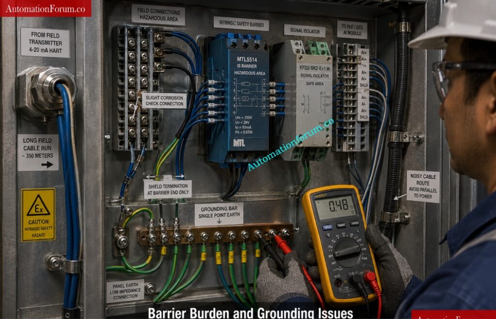
Barrier Burden and AI Card Loading Problems
Even though the current loop principle is robust, these field realities affect the actual current reaching the AI card.
This becomes especially visible during:
- Plant startup
- Brownfield modifications
- Migration projects
- Shutdown revamps
- Aging facilities
- Offshore platforms
- High humidity environments
A slightly corroded terminal in a junction box may create enough additional resistance to alter signal integrity.
- An overloaded IS barrier may reduce available loop voltage.
- Poor shield termination may introduce electrical noise.
- Improper grounding can create unstable readings that appear random.
Most engineers focus only on the transmitter while the real issue exists somewhere in the signal path.
Refer the below link to Fix 4-20mA Loop Faults Faster Using Loop Calibrators:
Most Common Causes of Field vs DCS Reading Mismatch

There are several reasons why the transmitter value in the field and the value in the control room do not match exactly. In many cases, the loop is still working, but one small issue is enough to create a visible difference in the displayed process value.
Incorrect LRV and URV Configuration
If the transmitter is configured with the wrong Lower Range Value or Upper Range Value, the output current will not represent the actual process correctly. Even if the sensor is healthy, the transmitter will send the wrong signal range, which leads to mismatch in the control room.
Wrong AI Scaling in DCS or PLC
Sometimes the transmitter is correct, but the analog input scaling in the DCS or PLC is wrong. If the input channel is not mapped properly, the control system will convert the received current into the wrong engineering value. This is one of the most common reasons for false mismatch during loop checking.
Engineering Unit Conversion Errors
A reading can appear wrong simply because different systems are using different units. For example, the transmitter may be configured in bar, while the DCS is showing psi or kPa. In these circumstances the values could be valid but seem to be mismatched because the units aren’t in sync.
Analog Input Card Calibration Drift
The analog input card itself can deviate from its original calibration over time. This means that the card may not read the loop current correctly even when the field transmitter is giving the proper value. A small drift in the card can cause a large inaccuracy in the reading shown.
Ground Loop Problems
Unwanted grounding channels can interfere with the signal and lead to unstable or wrong readings. Ground loops are a particular problem in noisy industrial situations, where several return pathways can corrupt the signal and cause the control room value to drift or vary.
Why 4-20mA Signals Still Dominate Industrial Automation Systems: Why not use 0-20mA & 0-15psi instead of 4-20mA & 3-15psi?
Cable Resistance and Voltage Drop Issues
Resistance can be introduced into the loop by long cable runs, broken conductors or poor cable quality. This can lower the available voltage and impact the current that reaches the AI card. In applications with a large span, even a little voltage loss might lead to a noticeable process fault.
Improper Shielding and Noise Pickup
If the cable shield is not terminated properly, the loop may pick up electrical noise from neighboring equipment, power cables or VFDs. This typically gives readings that are unstable, jitter or minor variations that make the value look questionable.
HART Multidrop Configuration Problems
HART multidrop mode allows numerous devices to communicate on the same loop via digital signals. The analog current interpretation can be problematic if the system is not setup correctly. This can cause strange readings or apparent discrepancy between the field device and the control room.
Incorrect Isolator Configuration
Signal isolators can safeguard and isolate loops, but if not adjusted appropriately might change the signal or impair accuracy. they can alter the signal or reduce accuracy. Wrong input or output settings can create mismatch even though the transmitter itself is functioning properly.
Intrinsic Safety Barrier Burden Issues
Intrinsic safety barriers add resistance and load to the loop. If the burden is too high, the transmitter may not have enough voltage headroom to drive the signal correctly. This could result in a low reading or weak signal on the AI card.
Faulty or Loose Terminals
If terminals are loose, rusted, or not well crimped, the signal route may be interrupted. The loop may still look alive, but the current may not flow cleanly. This sometimes results in intermittent mismatch, unstable readings or rapid value shifts.
Improper Loop Power Supply
If the loop supply is poor, unstable or set wrong, the transmitter may not work at the needed range. This can influence loop current and make the displayed value incorrect or inconsistent.
Generate Accurate 4-20mA Signals Without Calibration Mistakes: How to simulate 4-20ma signal with Loop Calibrator ?
Electromagnetic Noise Interference
Signal loop interference can be caused by electrical noise from neighboring motors, drives, transformers or power lines. This may not completely fail the loop, but it can cause small fluctuations, drift, or unstable displayed values.
Marshalling Cabinet Wiring Errors
Incorrect wiring inside the marshalling cabinet can easily create mismatch. A crossed wire, loose connection, or wrong terminal landing may allow the loop to work partially, but not accurately. This is why marshalling verification is always important during commissioning.
Shared Commons in AI Cards
Wrong Analog Input Card Type
Not all analog input cards behave the same way. Using the wrong type of card for the application may lead to scaling, burden or compatibility difficulties. The transmitter may output correctly, but the card may not interpret the signal as expected.
Low Resolution AI Modules
If the analog input module has low resolution, small changes in current may not be represented accurately. This becomes a bigger problem in wide span applications where tiny current differences can produce visible engineering value errors.
Faulty Transmitter Output Stage
Sometimes the transmitter itself has an internal output problem. The device may be indicating one value , but sending a little different current to the loop . This might be a bad output stage , or digital to analog conversion problem . This causes confusion since the local display looks okay, but the reading in the control room is wrong.
Many of these faults do not stop the loop completely. Instead, they only disturb the signal enough to create mismatch, drift, unstable readings, or small but important process value errors.
Loop Check vs Functional Test Mistakes Destroying Commissioning Quality: Loop Check vs Functional Test in Instrumentation Commissioning
Step by Step Troubleshooting Workflow: Field vs Control Room Reading Mismatch
Step 1 Verify the Transmitter Display
- Check what the transmitter itself is showing.
- Expected result: Transmitter PV and output current must be within the range set.
- If not, likely fault: transmitter setting, trouble with sensor, or problem with internal circuitry.
- Corrective action: Check transmitter configuration, spans, and health of the sensor.
Step 2 Measure Actual Loop Current
- Measure the current at the AI input in series using a calibrated multimeter or loop calibrator.
- Expected result: Current to be within tolerance of transmitter output.
- If not, unlikely to be at fault: cable loss, barrier load, terminal problem or power supply deficit.
- Corrective action: check full current path, measure point to point.
Step 3 Compare HART Output Current
- Read transmitter with HART communicator.
- HART value should equal transmitter display.
- If not, probably fault: transmitter setting or sensor mismatch.
- Corrective action: check sensor calibration and device parameters.
Step 4 Verify DCS Scaling
- Check LRV, URV and engineering unit conversion in DCS/PLC.
- DCS should take the current received and calculate PV appropriately.
- If not: probable fault, improper scaling or wrong channel setting.
- Corrective Action: Correct input range, raw count to engineering unit mapping.
4-20mA to PV Scaling Calculator for Precise Engineering Values: 4-20mA to PV scaling calculator
Step 5 Check AI Raw Counts
- Look at the raw input counts in the control systems.
- Expected result: Raw counts should follow closely the measured current.
- If not, possible fault: AI card calibration issue, channel fault.
- Corrective action: Check against a recognized current source and recalibrate if necessary.
Step 6 Validate Total Loop Resistance
- Measure total resistance of loop.
- Expected result: resistance should be in the limits of the transmitter and barrier.
- Excess cable length, broken conductors, poor connections. If not, likely a defect.
- Corrective action: Reduce burden, repair wire or enhance termination quality.
Step 7 Inspect Barriers and Isolators
- Check intrinsic safety barriers, isolators, and wiring.
- Expected outcome proper device type, correct polarity and acceptable burden.
- Wrong choice of barrier. Or wrong installation. If not, probable fault.
- Corrective Action: Verify panel drawings and install correct device if applicable.
Step 8 Check Grounding Continuity
- Make sure that grounding is done according to the plant philosophy.
- The expected result is a steady signal, without undesired ground pathways.
- If not, probable culprit: ground loop or floating shield.
- Corrective action: Modify grounding mechanism and eliminate parallel return pathways.
Step 9 Verify Shield Termination
- Ensure shields are terminated at the correct end only.
- no unintentional contact of shield with signal conductors.
- Probable fault if not: noise pickup and unstable current.
- Corrective action: re terminate the shield according to the standard.
Step 10 Perform Loop Simulation
- Inject a known signal into the AI card.
- Expected result: DCS should show the exact expected value.
- Probable fault if not: DCS scaling or AI card issue.
- Corrective action: isolate whether the fault is in the field loop or the control system.
Step 11 Use a Loop Calibrator Properly
- Simulate current and compare field and room readings.
- Expected result: full loop response should track the input.
- Probable fault if not: wiring, barrier, or AI channel problem.
- Corrective action: troubleshoot from field device to control room in sequence.
Step 12 Compare Engineering Units
- Make sure everyone is looking at the same units.
- Expected result: kg per hour should not be confused with percent, lb per hour, or raw current.
- Probable fault if not: unit conversion error.
- Corrective action: align transmitter, DCS, and historian units.
Control Valve DCS Loop Troubleshooting Checklist That Actually Works: Checklist for Troubleshooting Control Valve in DCS Loop
HART Communication vs Actual Loop Current
This is one of the biggest sources of confusion during commissioning.
The HART value comes digitally from the transmitter processor. The analog output current is what the DCS actually sees.
That means the HART communicator may show a healthy reading while the DCS shows an error, because the analog loop current has a problem somewhere between the transmitter and the AI card.
This matters during FAT, SAT, shutdown work, startup, migration, and loop checking because engineers often trust the digital value and ignore the analog path.
That is a mistake.
If the DCS sees 5.99 mA, it does not care that the HART value looks perfect. It will calculate the PV from the current it receives.
Safely Measure Instrument Loop Current Without Damaging Equipment: How to Safely Check the mA Current of an Instrument Loop Using a Multimeter
Practical Field Lessons Learned
Loose JB Terminal Created Reactor Temperature Instability
A slightly loose junction box terminal caused fluctuating milliamp readings. Operators suspected thermocouple instability for two days before discovering the loose terminal.
Wrong DCS Scaling Looked Like Transmitter Failure
A pressure transmitter was repeatedly recalibrated because the DCS reading was wrong. Root cause was incorrect AI scaling inside the PLC.
0.01 mA Created Major Custody Transfer Error
A small current drift occurred in a custody transfer flowmeter. The flow span was very large therefore the financial reporting inaccuracies were material.
Barrier Burden Caused Low Reading
The IS barrier replacement added further voltage load. The transmitter output current fell away a little, indicating a steady low flow.
Ground Loop Created False Level Reading
Multiple shield grounding points introduced unstable level transmitter signals during rainy season humidity conditions.
These are not textbook examples. These are common industrial realities.
Simulate 4-20mA Signals Correctly Using Loop Calibrator Techniques: How to simulate 4-20ma signal with Loop Calibrator ?
Best Practices to Avoid Field and DCS Reading Mismatch
- Use proper loop design from the start.
- Select quality cable with correct shielding.
- Follow one clear shield grounding philosophy.
- Size barriers and isolators correctly.
- Verify all AI card settings before loop checking.
- Use good ferrules and proper crimping.
- Measure total loop resistance.
- Keep marshalling clean and documented.
- Don’t just check the transmitter, check the whole loop.
- A good loop calibrator should be used.
- Maintain grounding integrity across the entire system.
- Calibrate the complete loop during commissioning.
4-20mA Loop Troubleshooting Techniques Every Technician Should Master: How to do troubleshooting of a 4-20mA loop?
Loop Current Drop vs Process Value Error Table
| Current at AI | Current Drop from 6.00 mA | Approximate PV Error on 0 to 150000 kg per hour span |
| 6.00 mA | 0.00 mA | 0 kg per hour |
| 5.99 mA | 0.01 mA | 93.75 kg per hour |
| 5.98 mA | 0.02 mA | 187.50 kg per hour |
| 5.95 mA | 0.05 mA | 468.75 kg per hour |
This table shows why small loop current drops can create visible process errors on large spans.
Loop Diagram Interpretation Skills Every Instrument Engineer Must Learn: What is a loop diagram and how to interpret it?
Key Takeaways: Why Loop Integrity Matters
- Tiny current drop equals large process impact.
- Absolute error increases with span.
- DCS sees actual current, not the transmitter processor value.
Loop integrity matters. - Loop checking is not just calibration.
- Wide range transmitters need extra attention.
PLC Analog Scaling Mistakes That Cause Serious Process Errors: Scaling Analog Values in Industrial Automation (PLC)
Frequently Asked Questions About Loop Checking and DCS Reading Mismatch
1. Why does the field transmitter reading differ from the DCS reading?
The transmitter display shows the internally calculated process value, while the DCS calculates the value from the actual received loop current. Small current differences in the loop can therefore create visible mismatch in the control room.
2. What is the main cause of field vs DCS reading mismatch?
Wrong scaling, ground issues, resistance in the loop, barrier overload, loose terminals and AI card configuration errors are the most common culprits. Even a good transmitter can be ugly if there are little interruptions in the signal path.
3. How is loop checking different from calibration?
Calibration makes sure that the instrument itself is correct . Loop checking makes sure the complete signal flow from the field device to the control room is correct . A healthy loop is not always a successful calibration.
4. Why does HART show correct values when DCS is wrong?
HART communication reads the transmitter digitally from its processor, but the DCS depends on the analog current reaching the AI card. A problem in the analog loop can therefore affect the DCS even when HART looks perfect.
5. Can a 0.01 mA difference matter?
Yes, especially in wide span applications such as flare flow or custody transfer when small current variances can cause huge inaccuracies in engineering values. The percent inaccuracy seems little but the effect on the process can still be large.
6. What should be checked first in analog input troubleshooting?
Check the transmitter display, the real loop current, DCS scaling and AI raw counts These tests immediately show whether the problem is in the transmitter, wiring or control system.
Turbine Flow Meter Scaling Calculator for Accurate Process Measurements: Turbine Flow Meter Coefficient and Scaling Factor Calculator
7. Can a barrier cause low loop current?
Yes. Intrinsic safety barriers or isolators might add strain in the loop and lower the amount of available voltage headroom. This could hinder the transmitter from providing the right current to the AI card.
8. What causes unstable loop readings?
Common causes of unreliable readings are loose terminals, grounding problems, insufficient shielding, moisture intrusion, electrical noise and poor crimping. These flaws may not kill the loop, but they can introduce drift and volatility.
9. Why is DCS analog input troubleshooting important?
The DCS calculates the displayed process value by using the current received at the analog input card, not the transmitter display. Thus, any signal problem from the field to the control room can influence the precision of the procedure.
10. What is the best way to avoid mismatch?
Refer the below link for the PLC Raw Count Scaling Secrets Most Technicians Still Ignore