- Practical Guide for Installation, Commissioning and Maintenance Engineers in Process Industries
- Why Grounding and Bonding Are Critical in Instrumentation Systems
- Grounding and Bonding: Instrumentation Perspective
- Grounding in Instrumentation Systems
- Bonding in Instrumentation Systems
- Instrument Earthing Philosophy in Process Plants
- Instrument Earth (Clean Earth) – Practical Explanation
- Pressure Transmitter Grounding and Bonding – Practical Example
- Common Grounding Mistakes in Field Instrumentation
- Bonding in Field Instrument Installation
- Temperature Transmitter on Reactor Vessel – Bonding Example
- Grounding and Bonding in Control Panels and Marshalling Cabinets
- PLC Marshalling Panel – Grounding Best Practices
- Cable Shield Grounding – Instrumentation Focus
- Best Practices for Instrument Signal Cable Shielding
- Flow Transmitter Signal Noise – Real Plant Case Study
- Grounding and Bonding in Hazardous Areas
- Example: Level Transmitter on a Hydrocarbon Tank
- Ground Loops in Instrumentation Systems
- Analyzer System Ground Loop – Case Study
- Commissioning Checks for Instrument Grounding and Bonding
- Maintenance Perspective: Grounding Failures Over Time
- Example: Intermittent pH Analyzer Failure
- Documentation and Tagging Best Practices for Instrument Grounding
- Applicable Grounding and Bonding Standards for Instrumentation
- Instrumentation Engineer’s Golden Rule for Grounding and Bonding
- FAQ on Grounding and Bonding in Instrumentation
Practical Guide for Installation, Commissioning and Maintenance Engineers in Process Industries
Grounding and bonding in instrumentation and control (I&C) systems in modern process industries are much more than just basic electrical safety. One of the most prevalent underlying causes of problems like unstable transmitter values, PLC analog input drift, DCS communication failures, nuisance interlocks, and unexplained control valve hunting is not grounding properly.
Why Grounding and Bonding Are Critical in Instrumentation Systems
Grounding and bonding have a direct impact on the following for engineers who install, commission, and maintain instrumentation:
- Measurement accuracy
- Signal stability
- Control system reliability
- Personnel safety
- Plant availability
This guide only talks about grounding and bonding from the point of view of instrumentation, using real plants as examples instead of textbook theory.
Grounding and Bonding: Instrumentation Perspective
Grounding in Instrumentation Systems
Grounding in instrumentation systems is the planned connection of:
- Instrument electronics
- Signal reference points
- Control system racks
- Instrument enclosures
to a stable earth reference.
Purposes of Grounding in I&C Systems
Protection of sensitive electronics
Low voltage and low signal levels are what modern smart transmitters, PLC I/O cards, analyzers, and DCS modules work with. Bad grounding makes them more likely to get damaged by surges, voltages that are too high, and early failure.
Reduction of electrical noise and interference
VFDs, motors, MCCs, welders, and switching power supplies can all be found in factories. Grounding correctly reduces EMI and RFI coupling into signals from both analog and digital instruments.
Providing a controlled fault current path
Grounding makes ensuring that fault current passes safely to the ground instead of via signal circuits or instrument housings if insulation fails.
Stabilizing analog and digital signals
A steady reference earth stops signal offset, drift, and short-term changes, notably in low-level analyzer signals and 4–20 mA loops.
The main goals of instrumentation grounding are to keep signals secure and reliable, but safety is always a must.
Learn the basic concept and different grounding methods used in practice: What is grounding in electricity and Types of grounding
Bonding in Instrumentation Systems
Bonding is the process of connecting all neighboring metal parts with electricity such that they all have the same electrical potential.
What Is Bonding and Why It Matters in Process Plants
- Instruments are mounted on pipes, vessels, structures, and skids
- Signal cables go a long way through the plant.
- Several earth spots can accidentally create noise routes.
Consequences of Poor Bonding in Instrumentation
- Instrument housings can have touch voltage on them.
- Ground loops are made
- The risks of static discharge go up.
Bonding makes guarantee that there is no harmful or noise-making potential difference between metal parts, even when there are faults, lightning, or switching surges.
Refer to this critical document for safe and reliable plant operation: Alarm & Trip Setpoint List in Instrumentation Engineering: The Most Critical Document for Plant
Instrument Earthing Philosophy in Process Plants
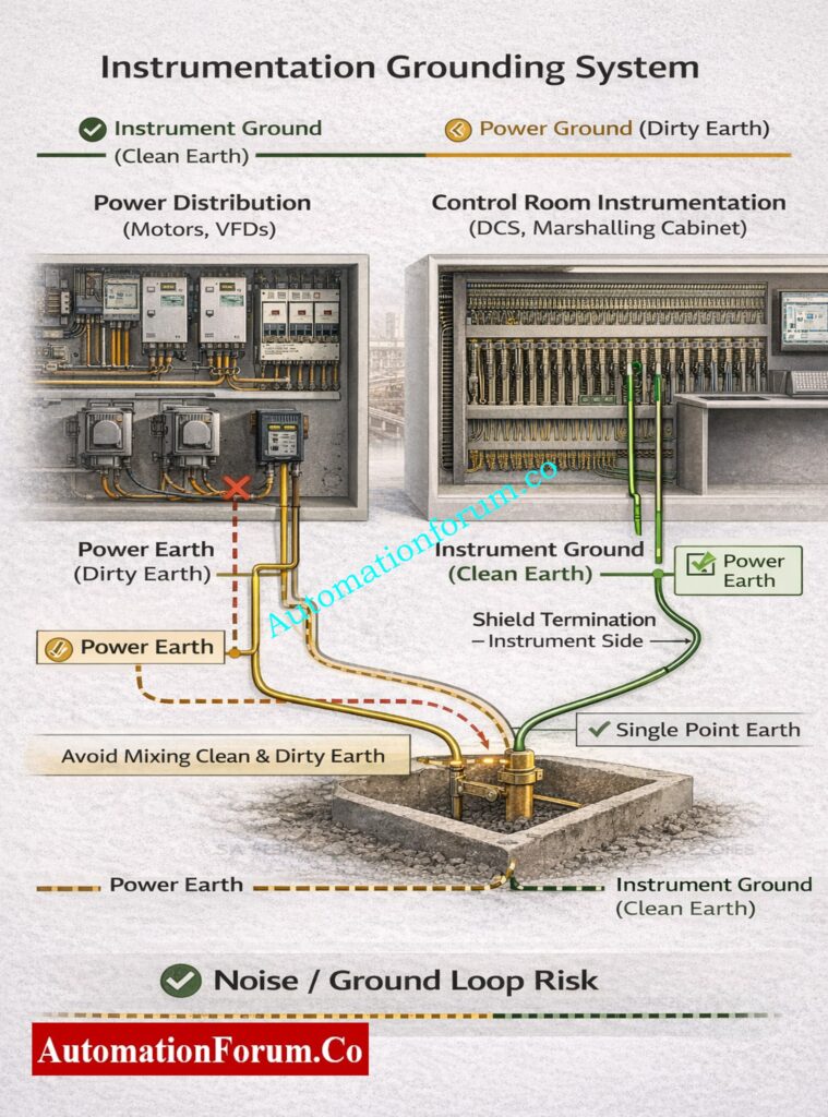
Most big process facilities use a “segregated earthing” system, which keeps separate earth systems apart to control noise and fault currents.
Segregated Earthing Concept in Instrumentation
Common ways to separate earthing are:
- Instrument Earth (Clean Earth) – for low-level signals
- Electrical / Power Earth (Dirty Earth) – for motors, MCCs
- Safety Earth – for personnel protection
- Static Earth – for hazardous areas
Instrumentation engineers should never mix these earths at random. If you connect things incorrectly, it defeats the whole point of segregation and causes noise problems that never go away.
Instrument Earth (Clean Earth) – Practical Explanation
What Is Instrument Earth?
Instrument Earth (Clean Earth) is a low-noise grounding system made particularly for sensitive instrumentation and control equipment, such field transmitters.
- Field transmitters
- PLC and DCS racks
- Analyzers
- Marshalling cabinets
- Control room panels
It is normally:
- Cut off from power earth
- Connected to the main plant earth grid at only one place
This single-point connection keeps ground loops and circulating currents from happening.
Understand the difference to avoid protection and safety mistakes: Difference between Earth Fault and Ground Fault
Pressure Transmitter Grounding and Bonding – Practical Example
Pressure Transmitter Construction Overview
A typical smart pressure transmitter has the following parts:
Metallic housing (Stainless Steel or Aluminum)
- Protects internal electronics from mechanical damage and harsh environments
- Works as an electromagnetic barrier to block electrical noise from outside.
- Must be correctly connected to keep static from building up and contact voltage from happening.
Internal electronics (sensor, signal conditioning, communication module)
- Changes the process pressure into a standard electrical signal
- Very sensitive to the quality of the ground and electrical noise
- Poor grounding has a direct impact on accuracy, stability, and long-term dependability.
Shielded signal cable (4-20 mA / HART)
- Twisted pair reduces inductive and capacitive noise.
- Shield stops EMI/RFI from motors, VFDs, and power lines.
- The shield termination mechanism decides if noise is blocked or added.
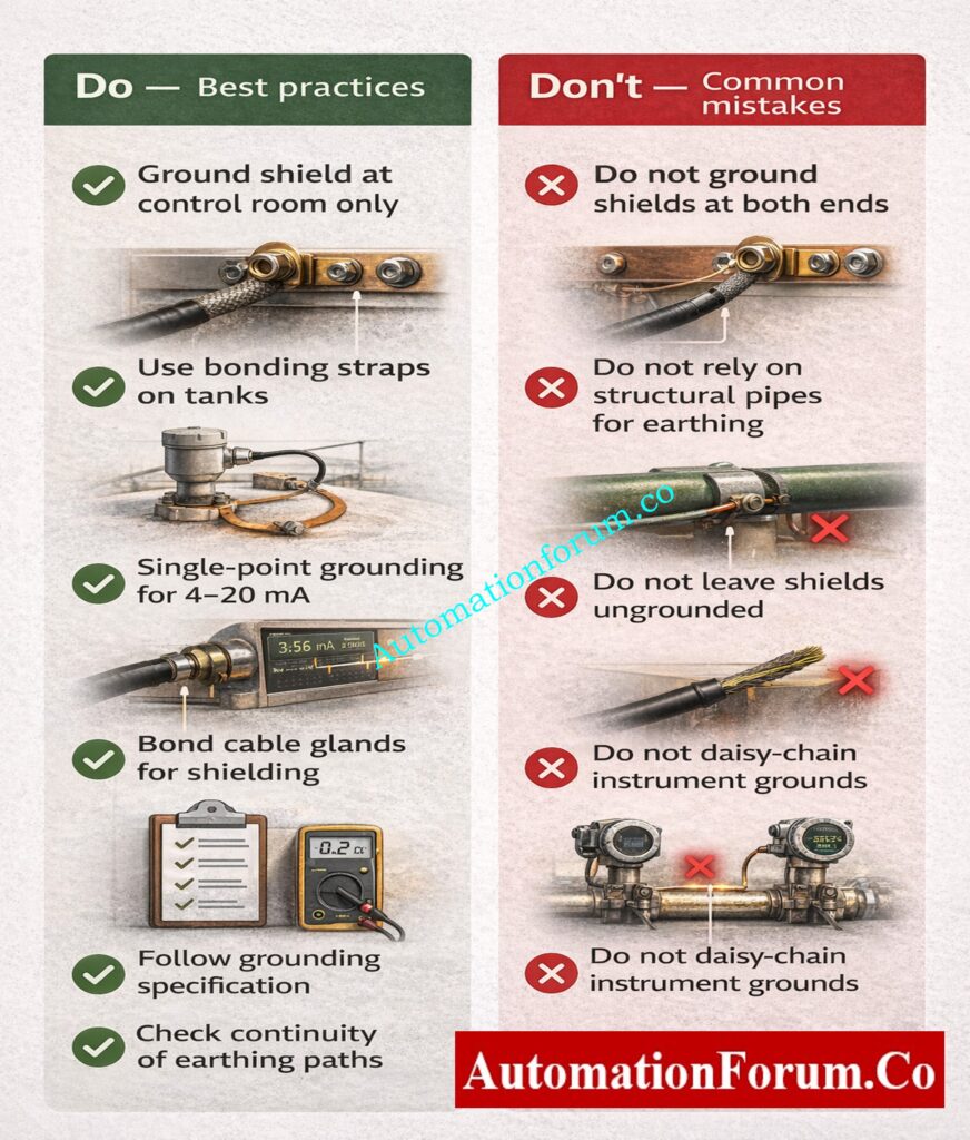
Correct Grounding and Bonding Practice
Transmitter body bonded to the process pipe
- Makes sure that the transmitter housing and the pipe have the same electrical potential
- Keeps static charge from building up on the instrument body and gives fault currents a low-impedance path.
- Bonded process pipe to the plant’s ground grid
Process pipe bonded to the plant earth grid
- Safely sends fault voltage and induced currents to the ground.
- Keeps the potential the same throughout all pipes and mounted instruments
- Lessens the chance of getting shocked while doing maintenance
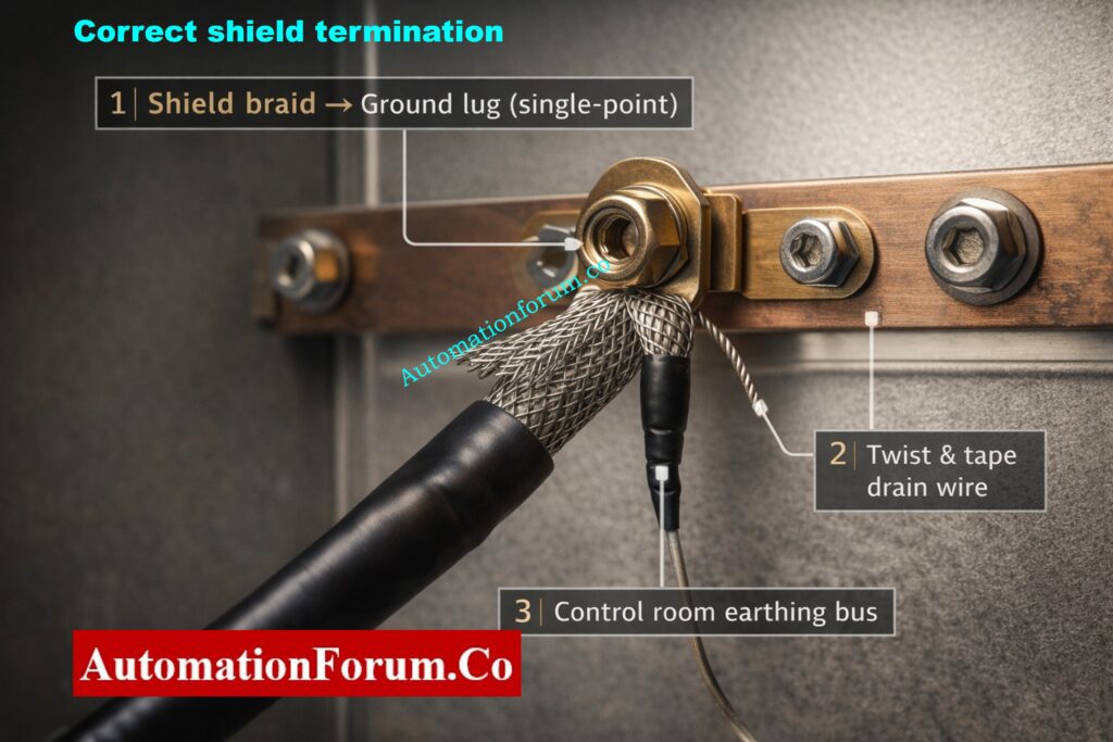
Cable shield grounded at control room end only
- Creates a single, clear point of reference for noise currents
- Stops currents from flowing because of variances in earth potential
- Keeps electronics on the field side separate from loud earths
Instrument earth terminated at the Instrument Earth Bar (IEB)
- This gives I&C systems a specialized low-noise earth reference.
- Keeps electrical and power earths apart
- Makes analog and digital signals more stable and consistent
Use this checklist during routine inspection and maintenance: Running Inspection Checklist of PLC Components in Control Panels
Common Grounding Mistakes in Field Instrumentation
Shield grounded at both transmitter and control room ends
- Makes more than one path to the ground for the cable shield
- Lets minor voltage variations push current through the shield
- It makes the shield an unintentional conductor of noise.
Consequences of Improper Shield Grounding
Ground loop formation
- Circulating currents move between different sites on the globe.
- Noise is put directly into the signal circuit
Fluctuating pressure readings
- Even when the process is steady, the transmitter output becomes unstable.
- Noise often gets louder when the motor begins or the load varies.
Unstable control loop behavior
- The controller responds to noise instead of real changes in the process.
- Control valves look for things they don’t need to.
- More wear on the final control elements
Compare both methods to understand their applications and limitations: What is the difference between underground cabling and overhead lines?
Bonding in Field Instrument Installation
Bonding Requirements for Field Instruments
Not only should each field-mounted equipment be electrically grounded, but it should also be bonded. Bonding makes the potential the same between metal parts, which makes both safety and signal quality better.
This includes:
Transmitter to pipe or mounting bracket
- gets rid of the voltage difference between the instrument body and the surface it is mounted on.
- Stops static discharge at the transmitter
Junction box to support structure
- Keeps the JB enclosure at earth potential
- Stops fault voltage from showing up on cable covers or glands
Cable tray to steel structure
- Stops trays from being floating conductors
- Lessens the amount of electromagnetic coupling that happens in instrument cables
Analyzer shelter to earth grid
- Keeps a common ground for sensitive analyzer electronics
- Makes measurements more stable and safe
Bonding Ensures:
No potential difference between metallic parts
- Removes the danger of touch voltage during regular operation and problems
Fault currents bypass signal wiring
- Keeps low-level signal circuits from getting broken
Reduced EMI pickup
- Reduces the amount of noise that gets into instrument wires and electronics
Clear the common confusion between neutral, earth, and ground: Difference between Neutral, Earth and Ground
Temperature Transmitter on Reactor Vessel – Bonding Example
For a temperature sensor that is set up on a reactor nozzle:
Transmitter housing bonded to mounting bracket
- Stops static from building up on the instrument casing
- Makes sure that maintenance is done safely
Mounting bracket bonded to vessel shell
- Equalizes the voltage between the transmitter and the vessel
- Gives a short, low-impedance channel for bonding
Vessel bonded to main earth grid
- Safely gets rid of static charges and fault currents
- Keeps the earth connection going through the reactor structure
Risks When Bonding Is Missing
Static charge can accumulate
- Static charge can build up, especially in dry settings or while working with hydrocarbons.
Fault voltage may appear on transmitter housing
- Makes it dangerous for maintenance workers to get shocked
Maintenance personnel face shock risk
- Especially when calibrating or replacing parts
Signal noise increases during process upsets
- Readings of temperature become unstable or wander.
Select the correct cables for safe operation in hazardous areas: What Cables to Use in Ex Zones: Complete Guide for Instrumentation & Control Engineers
Grounding and Bonding in Control Panels and Marshalling Cabinets
Essential Grounding Practices Inside Panels
Grounding and bonding are required technical techniques inside I&C panels, not just something people like to do.
Some things that must be done are:
Dedicated Instrument Earth Bar (IEB)
- Provides a clean, centralized earth reference for all I&C signals
- Stops power and instrument earths from mingling
Bonding of panel body to earth grid
- Keeps the enclosure at earth potential
- Keeps people and equipment safe during problems
Door bonding straps
- Keeps the earth connected even when the door is open
- Stops floating panel doors from working like antennas
Bonded DIN rails
- Makes ensuring that terminal blocks and modules have a steady earth reference
Earth terminals on terminal blocks
- Gives shield drains and earth conductors the right places to end.
PLC Marshalling Panel – Grounding Best Practices
Correct Instrument Grounding Inside PLC Panels
All analog commons referenced to the Instrument Earth Bar (IEB)
- Provides a stable reference for analog measurements
- Lessens drift and offset in PLC analog inputs
Shield drain wires terminated on earth terminals
- Properly sends noise currents away from signal conductors
Panel enclosure bonded to plant earth
- Ensures enclosure safety and EMC compliance
Problems Caused by Poor Panel Grounding
PLC analog input fluctuations
- Readings that are not stable even though the process conditions are stable
Random alarms
- False alarms that go off because of noise
Communication dropouts
- Loss of communication between PLC–DCS or PLC-HMI
Spurious trips during motor starts
- High inrush currents cause noise that impacts control signals.
Instrumentation Engineer’s Golden Rule
Bond all the metal together, ground the signal reference once, and make sure that noise only has one way to get to the ground.
Read the complete step-by-step guide here: Panel Door Earth Bonding Procedure: Ensuring Safety and Reliability
Cable Shield Grounding – Instrumentation Focus
Why Shield Grounding Is Critical for Low-Level Signals
Instrumentation signal cables contain low-level analog and digital signals, which makes them very sensitive to electrical noise. If not properly insulated and grounded, these wires act like antennae in a process plant.
Wrongly terminating the shield causes:
Electromagnetic Interference (EMI)
- Caused by motors, VFDs, transformers, and switching devices
- Causes unnecessary voltage to flow across signal wires
- Leads to an unsteady output from the transmitter and noisy trends.
Radio Frequency Interference (RFI)
- Comes from radios, wireless devices, and switches that work at high frequencies.
- It has a big effect on smart transmitters and digital communication.
- Can cause communication problems that come and go
Ground loop currents
- Happen when the shield is grounded in more than one place
- The shield lets circulating currents through.
- Noise is put directly into the signal reference
Key point:
A shield only functions if it is grounded properly. A shield that isn’t grounded properly is worse than no shield at all.
Follow this practical method to eliminate noise and signal instability: How to properly ground an Instrumentation System to reduce noise?
Best Practices for Instrument Signal Cable Shielding
Shield Grounding Recommendations by Signal Type
4-20 mA Analog Signals
- Grounded shield just at the control room (DCS/PLC) end
- Stops currents from flowing through the shield
- Keeps electronics on the field side separate from loud earths
Thermocouple Signals
- Grounded shield just at the receiver end
- Stops changes in earth potential from impacting millivolt signals
- Important for keeping the temperature right and stable
- Fieldbus / Digital Networks
- Grounding the shield according to the vendor’s instructions
- Some systems need to be grounded at both ends with capacitive coupling.
- Bad grounding makes communication unstable.
Analyzer Signals
- Grounded at one point most of the time
- Vendors of analyzers give specified locations for grounding
- Drift and calibration problems happen when there are more than one grounding point.
Get a clear explanation of earth pits and their role in grounding: What is an Earth Pit?
Flow Transmitter Signal Noise – Real Plant Case Study
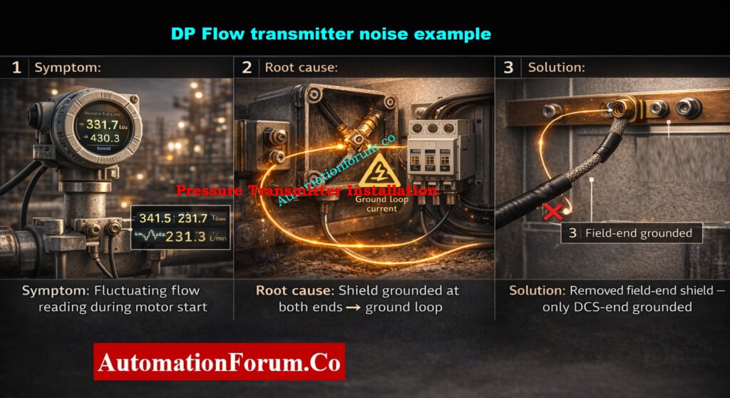
Symptoms Observed
- Flow reading changes every time an engine starts up nearby.
- The trend looks noisy, but the process flow is steady.
- Alarms may go out for a short time while the motor is running.
Root Cause Identified
- Grounded cable shield at both:
- Field junction box
- Control panel / DCS marshalling panel
- The starting current of the motor generates a variation in earth potential.
- The cable shield lets fault and noise currents pass through.
Corrective Action Taken
- Took away the shield grounding at the field junction box
- Only kept shield grounding at the DCS/control room end
- Checked that the shield drain wire was still connected
Result After Correction
- Reading of a stable flow
- No noise when motors start
- Restored control loop performance
Learn how proper earthing is implemented in real plants: Instrument Earthing Systems
Grounding and Bonding in Hazardous Areas
Static Grounding in Process Plants
Static electricity is a primary cause of fires in dangerous places. Bonding is required for safety and to follow the rules.
Key requirements:
- No matter what kind of signal they send, all instruments must be coupled.
- You also need to bond non-electrical tools like level gauges, thermowells, and sight glasses.
- Static charges need to be securely sent to the ground.
If you don’t regulate static, sparks can happen even if there aren’t any electrical problems.
Understand the technical reason behind single-end shield grounding: Why the Cable Shield is Grounded Only at the PLC or Control Panel Side
Example: Level Transmitter on a Hydrocarbon Tank
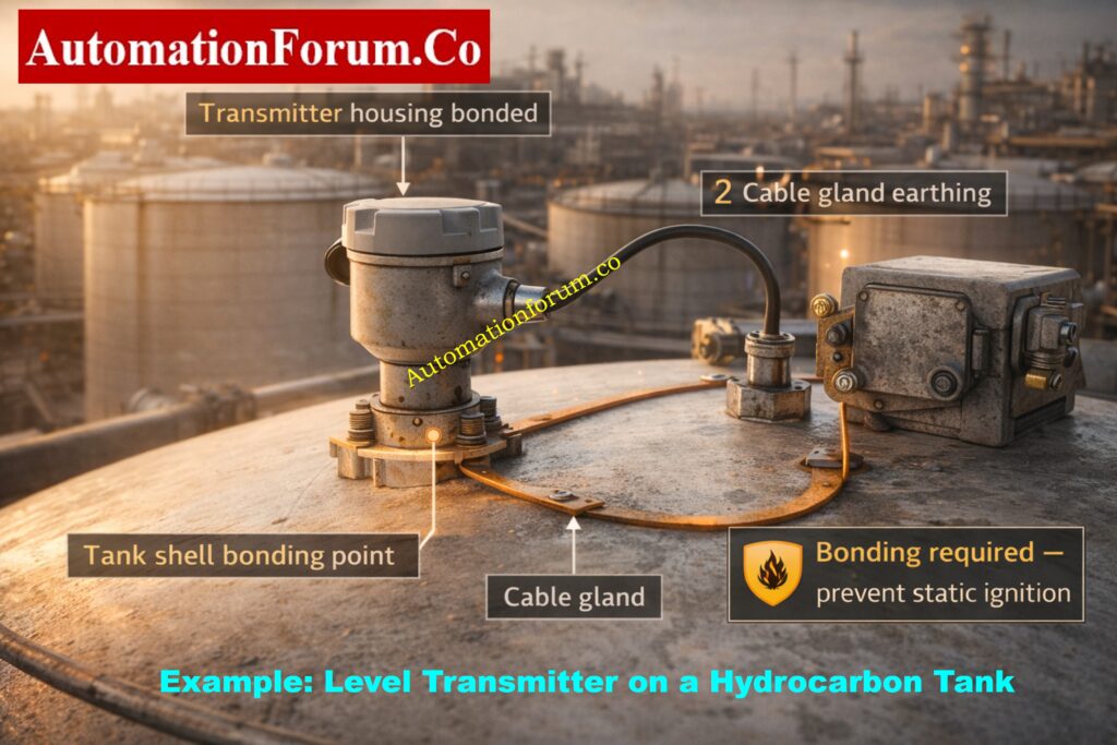
Bonding Required For:
Transmitter housing
- Prevents static buildup on metal enclosure
Tank shell
- Acts as the primary static discharge path
Cable gland
- Prevents static discharge at cable entry point
Junction box
- Ensures enclosure remains at earth potential
Failure to Bond Results In:
Static charge accumulation
- Especially in dry or flowing hydrocarbon service
Spark during maintenance
- When loosening cable glands or removing covers
Explosion risk
- High risk in Zone 0 / Zone 1 hazardous areas
Ground Loops in Instrumentation Systems
What is a Ground Loop?
A ground loop occurs when:
- Multiple earth paths exist for the same circuit
- Small voltage differences exist between earth points
- Circulating currents flow through signal return paths
These currents distort low-level analog signals and digital references.
Analyzer System Ground Loop – Case Study
Analyzer Grounded At:
- Analyzer shelter earth
- DCS panel earth
- Field junction box earth
Resulting Problems
- Analyzer output becomes unstable
- Calibration drifts over time
- Poor repeatability between samples
- Operators lose confidence in analyzer data
Correct Solution Implemented
- Defined single reference earth for analyzer signals
- Bonded all metallic parts together
- Removed duplicate grounding connections
- Used isolation where required
Commissioning Checks for Instrument Grounding and Bonding
During commissioning, instrumentation engineers must verify:
Bonding jumper continuity
- All metallic parts are electrically connected
Earth resistance values
- Instrument earth meets project specification
Correct shield termination
- Shield grounded at the correct end only
Instrument earth segregation
- Instrument earth kept separate from power earth
Door, gland, and tray bonding
- Ensures continuity even when doors are opened
Warning:
A grounding mistake left during commissioning becomes a permanent maintenance headache.
View and understand a typical grounding layout used in plants: Earthing Drawing
Maintenance Perspective: Grounding Failures Over Time
Typical Maintenance Findings
Corroded bonding straps
- Increased resistance and poor continuity
Painted-over earth points
- Earth connection becomes ineffective
Loose earth terminals
- Intermittent noise and false alarms
Broken shield drain wires
- Shield becomes floating and useless
Example: Intermittent pH Analyzer Failure
Root Cause
- Corroded earth connection inside junction box
- Earth resistance increased during rain
- Noise coupled into analyzer signal
Fix Implemented
- Cleaned all earth contact points
- Tightened earth terminals
- Replaced corroded bonding conductors
- Applied anti-corrosion compound
Documentation and Tagging Best Practices for Instrument Grounding
Instrumentation drawings must clearly indicate:
Instrument earth points
- Location and identification of IEB
Bonding jumpers
- Length, size, and connection points
Shield termination locations
- Field end or control room end
Earth bar references
Poor documentation causes people to do things wrong in the field, make the same mistakes again and over, and have problems with reliability that last a long time.
Applicable Grounding and Bonding Standards for Instrumentation
Commonly referenced grounding and bonding standards include:
- IEC 61140 – Protection against electric shock
- IEC 60079 – Explosive atmospheres
- ISA RP12.6 – Control of static electricity
- IEEE 1100 – Powering and grounding sensitive equipment
- IS 3043 – Indian standard for earthing
Instrumentation Engineer’s Golden Rule for Grounding and Bonding
Once you’ve grounded the signal, connect all the metal together, and don’t let noise have more than one way to get to earth.
In process industries, grounding and bonding are important parts of instrumentation, not only electrical formalities. Every I&C part, from field transmitters and analyzers to junction boxes and DCS panels, needs to be properly grounded to work correctly, stay stable, and be safe.
For engineers who install, test, and maintain instruments, knowing how to ground and bond things correctly gets rid of:
- Signal noise
- Measurement drift
- False alarms
- Unexplained failures
A plant that is well-grounded doesn’t talk about grounding much because nothing goes wrong.
If you don’t control the earth in instrumentation systems, the earth will control your signals.
Avoid wrong selection by understanding the key differences clearly: Thermocouple Wire vs. Thermocouple Extension Wire: The Complete Guide for Instrumentation Engineers
FAQ on Grounding and Bonding in Instrumentation
What Is Instrument Earth?
Instrument earth (clean earth) is a dedicated low-noise grounding system used only for instrumentation and control equipment.
It provides a stable reference for low-level signals and is connected to the plant earth at one single point to avoid noise and ground loops.
Why Is Shield Grounding Done at One End?
Shield grounding is done at one end only to prevent circulating currents in the shield.
Grounding at both ends creates ground loops, which inject noise into the signal instead of blocking it.
What Causes Ground Loops in Instrumentation?
Ground loops occur when multiple earth paths exist for the same signal circuit.
Small voltage differences between earth points cause circulating currents, which distort low-level analog and digital signals.