- Purpose of the FAT Procedure for Marshalling Cabinet
- Scope of the FAT Procedure for Marshalling Cabinet
- FAT Procedure – Reference Standards
- Responsibilities of Team Involved in Marshalling Cabinet FAT Procedure
- Required Tools and Equipment for Marshalling Cabinet FAT Procedure
- Step by Step Factory Acceptance Test (FAT) Procedure for Marshalling Cabinet
- Step 1: Visual Inspection
- Step 2: Mechanical Inspection
- Step 3: Electrical Inspection
- Step 4: Continuity and Insulation Resistance Tests
- Step 5: Functional Testing
- Step 6: Communication and Signal Testing
- Step 7: Power-Up and Load Test (If Required)
- Step 8: Final Inspection and Documentation Verification
- Step 9: Acceptance Criteria
- Step 10: Test Report and Sign-Off
- Factory Acceptance Test (FAT) Excel – Checklist for Marshalling Cabinet
- Common Mistakes in Factory Acceptance Tests (FAT) and Site Loop Checking
- What is the factory acceptance test (FAT) procedure?
The Factory Acceptance Test (FAT) verifies that marshalling cabinets fulfill both their design requirements and operational specifications before they reach the installation area. This document establishes the procedure for verifying the cabinet’s quality together with functionality along with wiring system and all associated documentation.
Purpose of the FAT Procedure for Marshalling Cabinet
The main goal of the FAT involves verifying that the marshalling cabinet satisfies project requirements as well as both industrial standards and operational performance specifications. All electrical and communication connections can operate according to design while on-site commissioning duration decreases thanks to this procedure.
Scope of the FAT Procedure for Marshalling Cabinet
This procedure defines inspection and testing standards for marshalling cabinets occurring during equipment manufacturing at manufacturer’s facilities. It includes:
- Visual inspection
- Mechanical verification
- The inspections involve tests for both electrical continuity and insulation resistance.
- Functional testing
- Documentation verification
FAT Procedure – Reference Standards
- IEC 61439 – Low Voltage Switchgear and Controlgear Assemblies
- IEC 60204 – Safety of Machinery – Electrical Equipment
- IEEE Std. 1100 – Powering and Grounding Electronic Equipment
- Customer project specifications
Responsibilities of Team Involved in Marshalling Cabinet FAT Procedure
- The manufacturer must fulfill technical requirements through testing capabilities as part of their responsibilities.
- End users must witness the FAT procedure to check compliance of the system.
- Third-Party Inspector (if applicable): Ensures adherence to standards and specifications.
Required Tools and Equipment for Marshalling Cabinet FAT Procedure
- Multimeter
- Insulation resistance tester (Megger)
- Earth continuity tester
- Function generator (for signal simulation)
- Power supply (as per system voltage requirements)
- Communication testing tools (as applicable)
- Standard FAT checklist
- Thermal imaging camera (for heat dissipation checks)
- Users need a torque wrench to confirm proper tightening of terminals.
Refer the link to understand the Marshalling Cabinet drawing and its significance
Step by Step Factory Acceptance Test (FAT) Procedure for Marshalling Cabinet
Step 1: Visual Inspection
- Check that the cabinet has proper structure integrity along with correct door alignment and appropriate ventilation openings.
- The project requirements must be satisfied by the selected paint and its surface finish.
- Confirm that all nameplates and identification labels as well as terminal markings remain in place.
- All components need to have their correct grounding and bonding connections verified.
- Check that internal components match the specifications of approved drawings.
- Verify that installed converters contain all required signal elements including current to voltage converters and voltage to current converters as well as temperature signal converters.
- Technical team members must establish the physical existence and correct placement of temperature transmitters alongside PLC modules together with power supply units, interface modules and communication gateways.
- Check that ventilation fans remain in correct positions with working functionality.
- Perform a check to verify both the presence of surge protection devices and their functional status.
- Signal wires should be clearly separated from power cables through correct wiring practices.
Step 2: Mechanical Inspection
- Check that all doors and panels and locking mechanisms move with normal operation.
- Examine the integrity of cable entry points and gland plate components.
- The inspector needs to examine the equipment for components that are loose and test for edges that are sharp or detect any problems with the assembly process.
- The system should have operational ventilation systems with effective heat dissipation mechanisms.
Step 3: Electrical Inspection
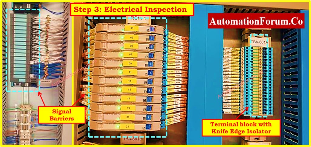
- Check that the electrical wiring matches the approved schematics together with the termination schedules.
- The installation of cables and wire terminations must follow established industry protocols.
- You must examine terminal tightness with a torque wrench.
- Inspection must confirm that interface modules and power supplies along with converters have their grounding connections set correctly.
- Examine the condition of fuses together with MCBs (Miniature Circuit Breakers) while assessing power distribution integrity.
- Ensure power supply redundancy along with automated power failover system functionality delivers the required specifications.
Step 4: Continuity and Insulation Resistance Tests
- Examine all wiring connections with the help of a multimeter during continuity tests.
- Perform insulation tests with a megohmmeter set to apply 500V or 1000V for control circuits and 250V for communication circuits and 5kV for high-voltage circuits after applicable.
- Check the integrity of grounding systems while measuring earth resistance values.
- Check shield continuity for signal cables.
Step 5: Functional Testing
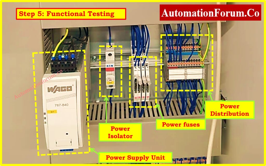
- After applying power to the cabinet you should check voltage levels throughout different locations.
- Test modules and interface modules by providing simulated signals that ensure their correct operation as well as the temperature transmitters and PLC modules.
- Perform validation of control communication standards which include Modbus RTU, Modbus TCP/IP, Profibus DP, Foundation Fieldbus and Ethernet/IP and other protocols.
- Check alarm and trip circuits for correct functionality.
- Conduct verification of the system safety features by analyzing the interlocking and fail-safe mechanisms.
- The system requires testing of power supply redundancy alongside interface module and communication gateway redundancy.
- Check status LEDs and indicators for proper operation.
- Test the signal isolators and converters to ensure they operate correctly.
Must read: Factory Acceptance Test (FAT) Activities for SCADA System: Step-by-Step Checklist
Step 6: Communication and Signal Testing
- Test how signals transmitted from the marshalling cabinet reach the control system.
- The function generator together with appropriate software tools must be utilized to test analog and digital I/O signals.
- Signal quality tests should include proofs of accuracy as well as response time measurements.
- Test the signal conversion mechanism installed in the marshalling cabinet to verify proper operations between 4-20mA and 1-5V and RTD to 4-20mA conversion types.
- Each signal should undergo a complete loop testing procedure.
Step 7: Power-Up and Load Test (If Required)
- Test the cabinet operation through simulated load conditions to check for operational stability while power is active.
- Thermal imaging cameras should be used to detect cabinet temperatures that rise above normal levels.
- Examine the equipment by listening for abnormal noises and inspecting for fan vibrations or any abnormal device behavior.
- Check that the system operates within specified load parameters while verifying redundancy in power supply systems.
- Check the power consumption rates to verify they meet design requirements.
- Throughout testing verify that each component of the cooling system operates correctly including ventilation fan functionality.
Step 8: Final Inspection and Documentation Verification
- An inspector must examine test documentation and ensure that all test results satisfy the FAT specifications.
- Compare as-built documentation with physical components to identify any discrepancies that need correction.
- All recorded deviations should undergo documentation and require corrective measures for necessary adjustments.
- Field technicians need to confirm that wiring schematics and Bill of Materials (BOM) list match the actual installed components together with termination drawings.
Refer the below link for the Shutdown Maintenance Procedure for Marshalling Cabinets in Process Plant
Step 9: Acceptance Criteria
- All marshalling cabinets must fulfill their design requirements defined in the approved drawings and specifications.
- All electrical wiring needs to successfully complete tests for insulation resistance and continuity checks.
- All functional testing must demonstrate component functionality.
- Physical examination must reveal no signs of defects and installation errors together with an absence of damages.
- The complete operation of signal converters along with interface modules and temperature transmitters should be ensured.
- All technical documentation needs to remain complete and precise alongside its regular updating.
Step 10: Test Report and Sign-Off
A comprehensive FAT Completion Report must be generated with documentation signatures at end of successful FAT evaluation. including:
- Inspection checklists
- Test data and results
- Photographic evidence (if required)
- The document contains all nonconforming items together with their corrective measures.
- Measuring instruments which participated in the FAT should have their calibration certificates available.
- Signatures from responsible parties (Manufacturer, Customer, Inspector)
Click here for Factory Acceptance Test (FAT) of a PLC Panel: A Step-by-Step Basic Guide
Factory Acceptance Test (FAT) Excel – Checklist for Marshalling Cabinet
This checklist ensures marshalling cabinets meet design, operational, and safety requirements before installation, reducing commissioning issues.

Refer the below link for the Downloadable Factory Acceptance Test (FAT) Excel Checklist for Marshalling Cabinet
You can download more checklist by Click on 50+Collection of Essential Instrumentation and Automation Control System Checklists
Common Mistakes in Factory Acceptance Tests (FAT) and Site Loop Checking
The successful execution of a FAT minimizes system problems during commissioning thus enabling a seamless site installation process. The stakeholders need to perform thorough inspections and tests on the marshalling cabinet to confirm its reliability and functionality prior to deployment.
Multiple common errors occur during Factory Acceptance Tests (FAT) and site loop checking activities such that they trigger delays and system errors and malfunctions. The following list includes frequent mistakes identified during activities and FAT and site loop checks.
- Incorrect Cable Selection: Use of the wrong type of multi-pair/multi-core cables (e.g., individual shield vs. overall shield).
- The terminal points contain improper wire connections which lead to loose wiring.
- The incorrect application of ferrules, lugs and terminations leads to improper Lugging and Termination.
- Incorrect Cable Glands: Improper selection or installation of cable glands.
- Wiring mistakes occur when junction boxes and marshalling cabinets receive improper connections.
- A frequent error occurs when common and signal cables are mistakenly interchanged under MCC Interface termination procedures.
- Polarity Reversal in Analog Signals Occurs Due to Incorrect Wiring of Signals.
- The incorrect installation of grounding and shielding stands as a major error in marshalling cabinets.
- The incorrect setup of field instruments includes wrong configuration of upper/lower range settings and square root calculations together with offsets.
- Control System Channel Misconfiguration occurs when users select improper active/passive/3-wire signal configuration settings.
- Fuse Issues: Blown fuse, missing fuse, improper fuse rating, or open terminals.
- Technical Failures Arise from Incorrect Digital Signal Contacts When Users Choose Between Normal Open or Normal Closed (NO/NC) Contacts.
- Digital Output Signal errors arise from the improper selection of dry contacts instead of wet ones.
- The presence of unwanted voltage inside dry contacts represents a Interrogation Voltage issue.
- Incorrect component selection and improper connections cause failures in relays as well as isolators and barriers.
- Incorrect Power Supply Module Sizing: Improper power module or MCB (Miniature Circuit Breaker) rating.
- The use of wires with improper colors or sizes which fail to match requirements constitutes non-compliance in internal wiring.
- External Power Supply Oversight: Lack of consideration for external power in 4-wire instruments.
- The identification of these typical mistakes in both FAT and site loop testing leads to better system reliability and faster troubleshooting results.
Click to read Site Acceptance Test (SAT) Procedure for PLC Systems
What is the factory acceptance test (FAT) procedure?
The Factory Acceptance Test (FAT) represents a quality control mechanism that companies use to guarantee equipment compliance with customer requirements before product delivery. This test verifies that equipment works properly with its design requirements and maintains conformity to both specifications and contractual terms. Before sending the product the manufacturer conducts a FAT which combines inspections and performance evaluations and functional tests to detect potential issues.