What is Latching in PLC
Latching in PLC (Programmable Logic Controller) is a commonly used control logic technique where an output remains energized even after the initiating input signal is removed. This behavior is essential in industrial automation systems where momentary inputs, such as push buttons, must control continuous operations like motors, pumps, and conveyors.
Latching logic is also known as:
- Holding circuit
- Seal-in circuit
- Self-maintaining circuit
Why Latching Is Important in Industrial Automation
In real industrial environments:
- Start push buttons are momentary
- Operators do not keep buttons pressed
- Equipment must continue running safely
Latching allows the PLC to remember the output state until a defined stop or reset condition occurs. This improves operational reliability, safety, and ease of control.
General Latching Concept
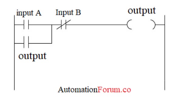
Figure shows the basic PLC latching principle using generic inputs and output.
Explanation of Figure Logic
- Input A → Start command (Normally Open contact)
- Input B → Stop command (Normally Closed contact)
- Output → Controlled device (motor, relay, etc.)
How It Works:
- When Input A is momentarily energized, the output coil turns ON.
- The output’s own auxiliary contact closes in parallel with Input A.
- This creates an OR logic path, allowing the output to remain ON even after Input A is released.
- When Input B is activated, the normally closed contact opens.
- The circuit breaks, and the output turns OFF.
Even if Input A is no longer active, the output remains energized until Input B is operated. This is the fundamental principle of PLC latching.
Practical Motor Control Example Using PLC Latching
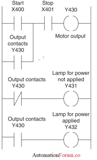
Figure illustrates a real industrial application of latching using a motor, start/stop push buttons, and status indication lamps.
Address Description:
- X400 → Start push button (NO)
- X401 → Stop push button (NC)
- Y430 → Motor output
- Y431 → Lamp for power NOT applied
- Y432 → Lamp for power applied
Motor Start–Stop Latching Logic (Rung 1 – Figure)
Operation:
- Pressing Start (X400) energizes output Y430.
- The output contact Y430 closes in parallel with the Start button.
- The motor continues running even after the Start button is released.
- Pressing Stop (X401) opens the NC contact.
- Output Y430 de-energizes, stopping the motor.
This rung forms a classic PLC holding circuit used in almost every industrial motor control application.
Power OFF Indication Logic (Rung 2 – Figure)
Explanation:
- The normally closed contact of Y430 is used.
- When the motor is OFF, Y430 is de-energized.
- The contact remains closed, energizing lamp Y431.
- This lamp indicates power not applied to the motor.
This ensures clear visual feedback for operators and maintenance staff.
Power ON Indication Logic (Rung 3 – Figure)
Explanation:
- A normally open contact of Y430 is used.
- When the motor runs, Y430 energizes.
- The contact closes and turns ON lamp Y432.
- This lamp indicates motor running / power applied.
Using separate ON and OFF indication lamps is a standard industrial practice for safety and diagnostics.
Key Advantages of PLC Latching Logic
- Allows control using momentary push buttons
- Prevents accidental shutdowns
- Improves operator safety
- Easy to implement and troubleshoot
- Essential for motors, pumps, compressors, and conveyors
- Widely accepted in IEC and industrial standards
Where PLC Latching is Commonly Used
- Motor control circuits
- Pump start/stop systems
- Conveyor belts
- Process plant equipment
- Machine automation panels
- Control room operations
PLC latching is a fundamental ladder logic concept that enables an output to stay energized even after the initiating input is removed. By using the output’s own contact as a feedback path and a normally closed stop contact for reset, latching provides safe, reliable, and industry-proven control logic.