- Required Reference Documents DP Transmitter FAT
- Step by Step Factory Acceptance Test (FAT) procedure for DP Transmitter
- Step 1: Visual Inspection
- Step 2: Dimensional Tests
- Step 3: Required Tools for Functional Test
- Step 4: DP Transmitter Smart Features Testing
- Step 5: 5-point Calibration Test (Up and Down Cycle)
- Step 6: Electrical Functional Test
- Step 7: Test for Protection Against Foreign Particles
- Step 8: Environmental Tests
- Step 9: DP Transmitter Drift Tests
- Step 10: EMI/EMC Test for DP Transmitter
- Step 11: Temperature Variation Test for DP Transmitter
- Step 12: Miscellaneous Checks
- Factory Acceptance Test (FAT) Checklist for Differential Pressure Transmitter
- Test your knowledge: DP Type Flow Measurement Transmitter
During Factory Acceptance Testing of Differential Pressure Transmitters technicians perform a systematic evaluation to verify that equipment meets technical requirements and functional specifications before product deployment.
The FAT procedure is intended to cover all critical aspects of the differential pressure transmitters during the procurement and manufacturing stages. It serves as a guideline to ensure that all necessary checks are performed before the acceptance of the items.
Required Reference Documents DP Transmitter FAT
The procedure utilizes multiple essential documents which include the following:
- Approved Datasheet: Contains technical specifications and performance criteria.
- Approved Quality Assurance Plan (QAP): Outlines the quality standards and testing protocols.
- Approved Follow-up Sheet: Provided to the successful bidder, detailing specific requirements and follow-up actions.
Step by Step Factory Acceptance Test (FAT) procedure for DP Transmitter
Step 1: Visual Inspection
Quantity Check
Ensure the quantity of transmitters available matches the ordered quantity.
Nameplate Verification
Examine the nameplate for compliance with specifications, including:
- Manufacturer Name
- Model Number
- Serial Number
- Tag Number
- Measurement Range
- Power Supply Requirements
- Enclosure Protection Rating
Material Verification
Confirm material composition of key components:
- Sensor
- Gaskets and O-rings
- Flange and Screws
- Transmitter Housing (material and color as per specifications)
Step 2: Dimensional Tests
Process Connection
Check that the DP transmitter type, size, and pressure rating match the technical specifications.
Inlet Probe Thread Check
Verify the DP transmitter inlet probe threads using a measuring tool to ensure correct threading.
Conduit Connection
Ensure the type and size of the conduit connection for cable connection are match with requirements.
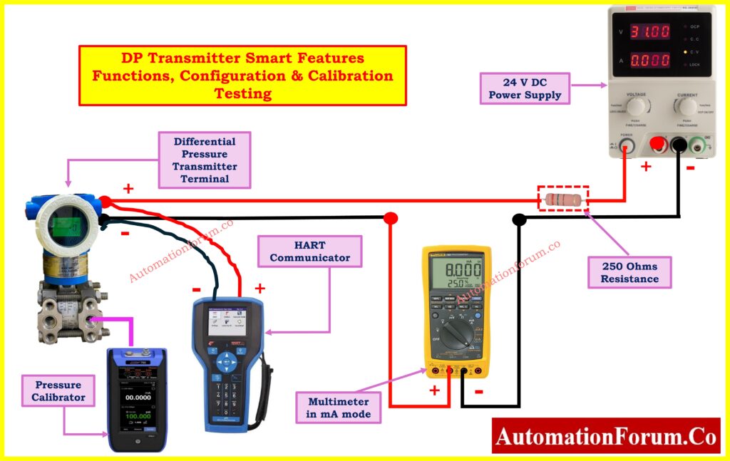
Step 3: Required Tools for Functional Test
Functional tests require specific instruments on the test bench, including:
- HART Communicator: For configuration and diagnostics of transmitter parameters.
- Power Supply: 0 to 24VDC with ±0.1% voltage tolerance.
- Pressure Calibrator: For calibration, with accuracy at least three times better than the transmitter under calibration.
- Multimeter: For measuring transmitter output current and supply voltage.
Click here for Flowrate to Differential Pressure (DP) Calculator
Step 4: DP Transmitter Smart Features Testing
Configuration via Handheld Terminal (HHT)
Use a Handheld Terminal (HHT) like HART communicator to configure and validate the transmitter settings.
Diagnostic Functionality
Verify the Differential Pressure Transmitters (DPT)’s built in diagnostic capabilities. Perform tests on at least one transmitter per range.
General Feature Testing
Verify the following parameters in Differential Pressure Transmitters (DPT) :
- Measurement & Calibrated Range
- Output Signal Type
- Power Supply Voltage Range
- Mounting Orientation
- Zero & Span Adjustments
- Integral Display
- Vent & Drain Valves
- Vacuum Protection
- Linear & Square Root Extraction
- Turn-Down Ratio
- Response Time & Damping
- Power-Up Time
- Mounting Brackets & Cable Glands
Step 5: 5-point Calibration Test (Up and Down Cycle)
- Calibration is performed over the full range (100 to 100 mmWC) at five points for both up and down cycles.
- This test is conducted for 100% of the lot.
Refer the below link for the Step by Step Calibration Procedure for Differential Pressure Transmitter
Step 6: Electrical Functional Test
Insulation Resistance (IR) Test
- Measure the insulation resistance between the transmitter body and its terminals (shorted).
- The resistance should be greater than 100 M? at 100V DC after 1 minute.
Step 7: Test for Protection Against Foreign Particles
Degree of Protection Dust Protection(IP6X)
- The Device Under Test (DP transmitter ) shall be placed inside a dust chamber.
- The dust chamber shall be maintained under a vacuum pressure of -20 mbar.
- Talcum powder shall be used as the test dust, with an approximate quantity of 2 kg.
- The talcum powder shall be kept suspended in the air by a continuous stream of airflow.
- The talcum powder shall be sieved through a mesh with a sieve size of 0.075 mm to ensure uniform particle size.
- The chamber’s air change rate shall be 40 times the volume of the DUT to ensure proper circulation and exposure.
- The test duration shall be 8 hours to simulate prolonged exposure to dust.
- After completing the 8-hour test, the DUT shall be visually inspected for any signs of talcum powder ingress inside the enclosure.
- A performance test must be done on the DP transmitter to validate proper functionality and required specifications after exposure.
- All observed deviations along with any discovered signs of dust entry must be recorded for reporting purposes.
Degree of Protection Water Protection(IPX7)
- The DP transmitter needs to undergo a water spraying procedure to check its ability to withstand water penetration..
- The test shall be conducted using a water nozzle with a diameter of 6.3 mm.
- Water shall be sprayed at a jet pressure of 30 KPa.
- The jet speed of the water flow shall be maintained between 12 to 13 liters per minute.
- The distance between the water nozzle and the DP transmitter shall be 3 meters.
- The test duration shall be 15 minutes to ensure adequate exposure.
- After the 15-minute water exposure, the DP transmitter shall be visually inspected for any signs of water ingress into the enclosure.
- A performance test shall be conducted on the DP transmitter to verify that it functions correctly and meets the required operational specifications after exposure.
- Any signs of water leakage or performance degradation shall be documented and reported.
Click here for Differential Pressure Transmitter Commissioning Checklist for Flow Measurement Applications
Step 8: Environmental Tests
Dry Heat Test
- The DUT shall be subjected to a controlled temperature of 55°C ±2°C at 40% Relative Humidity (RH) for 16 hours.
- The temperature shall be gradually increased to 55°C over 2 hours, then held at 55°C for 12 hours, followed by a gradual cooling to ambient temperature over 2 hours.
- Pre-heating or pre-soaking may be performed depending on the test facility.
- After a recovery period of 1 hour, a performance check shall be conducted to verify functionality.
Damp Heat Test
- The DUT shall be subjected to a damp heat test at 40°C ±2°C with 95% RH in a controlled testing chamber for 24 hours.
- The temperature shall be gradually increased from 25°C to 40°C over 2 hours, during which RH shall be kept below 80%.
- The DUT shall then be held at 40°C for 22 hours with 98% RH, followed by a gradual cooling to 25°C over 2 hours.
- Pre-heating or pre-soaking may be performed depending on the test facility.
- After a recovery period of 1 hour, a performance check shall be conducted to ensure proper functionality.
Click here for Differential pressure Flow Transmitter Output Calculator
Step 9: DP Transmitter Drift Tests
Short Time Drift Test (72 Hours)
- The transmitter shall be set at its minimum span, and the test shall be conducted at ambient temperature.
- An input at 50% of the set span shall be applied, and the transmitter shall be powered ON.
- The test shall run for 72 hours, with readings recorded every hour.
- The input shall be maintained at the set value throughout the test. The closeness of the recorded readings shall determine the repeatability of the transmitter.
Long Time Drift Test (30 Days)
- The transmitter shall be set at its calibrated span, and the test shall be conducted at ambient temperature for 30 days.
- An input at 10% of the set span shall be applied for one week, followed by an input at 90% of the span for the next week.
- This alternating pattern shall continue every week throughout the test duration.
- Drift in measurement shall be recorded for both 10% and 90% of the span to evaluate the long-term stability of the transmitter.
Step 10: EMI/EMC Test for DP Transmitter
The transmitter shall be set at its calibrated span, and an input at 50% of the calibrated span shall be applied. The transmitter shall be subjected to emission levels equivalent to low voltage AC mains as per IEC 61000-6-4 standards.
For a frequency range of 0.15 MHz to 0.5 MHz, the emission levels shall be:
- 79 dB(µV) Quasi-Peak
- 66 dB(µV) Average
For a frequency range of 0.5 MHz to 30 MHz, the emission levels shall be:
- 73 dB(µV) Quasi-Peak
- 60 dB(µV) Average
The transmitter’s performance shall be monitored during the test, and the maximum allowable error should not exceed 0.05% of the Upper Range Limit (URL).
Step 11: Temperature Variation Test for DP Transmitter
The transmitter requires testing at three different ambient temperature conditions which include reference temperature and 30 – 35°C and 40 – 45°C. Test conditions will be applied to the Dp transmitter through exposure to designated oven temperatures..
- After reaching the specified temperature, a soaking time of 1 hour shall be maintained.
- A 5-point calibration at 1:20 TD shall be conducted for one complete cycle on the transmitter.
- The temperature drift observed during the test must remain within the vendor’s specified temperature drift limits.
Step 12: Miscellaneous Checks
Mounting Hardware Verification
Check the availability of the necessary mounting accessories which consist of brackets and cable glands.
- Mounting Accessories
- Brackets
- Cable Glands
Documentation & Spare Parts Verification
The following documents along with spare parts need to be present:
- Technical Specifications
- User & Service Manuals
- Test Reports (as per QAP)
- Warranty/Guarantee Certificates
- Test spare components if applicable.
Factory Acceptance Test (FAT) Checklist for Differential Pressure Transmitter
This FAT checklist ensures Differential Pressure Transmitters meet technical, functional, and quality standards before deployment through rigorous testing.
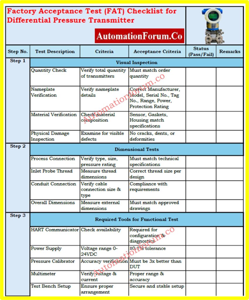
Download the FAT checklist for Differential Pressure Transmitters from below link
Click here for 50+Collection of Essential Instrumentation and Automation Control System Checklists
Test your knowledge: DP Type Flow Measurement Transmitter
Test your knowledge of DP flow measurement transmitters with this advanced troubleshooting quiz! Enhance your expertise, learn practical solutions, and tackle common industry challenges. Let’s see how well you understand DP transmitters!
Refer the below link to test your knowledge of DP flow measurement transmitters
 procedure for Differential Pressure (DP) Transmitters, ensuring compliance, accuracy, and reliability before deployment.)