- How do you measure tank level with DP transmitter?
- For example in the case, a DP type transmitter fitted to determine the level of the boiler feed water tank
- To troubleshoot issues with a DP type level transmitter, follow the common methods listed below
- Troubleshooting No output signal:
- Troubleshooting Low output signal
- Troubleshooting Repeated output errors:
- Troubleshooting The output is showing constant value:
- Troubleshooting Unstable (erratic) signal from the transmitter:
- Troubleshooting the transmitter display is off and not showing any value:
- Troubleshooting Transmitter showing level that is higher than the real:
- Troubleshooting Transmitter showing level that is lower than the real:
- Troubleshooting Transmitter output signal value fluctuations:
- Troubleshooting Sluggish Reaction
- Troubleshooting Mismatch between field and PLC/DCS flow values:
A differential pressure transmitter measures the pressure difference between the liquid and gaseous phases of a fluid within a closed tank to determine level. As an inferential measurement, level is measured using a DP Transmitter device. The diaphragm of a DP Transmitter detects the head pressure generated by the height of the fluid within the vessel. To get the right level measurement, multiply this amount by a density variable.
How do you measure tank level with DP transmitter?

- There are two legs that are piped to the transmitter: the working leg and the reference leg.
- The working leg is piped into the transmitter’s positive port, while the reference leg is piped into the transmitter’s negative port.
- The maximum permissible level of water in the tank is represented by the reference leg.
- The water should always be in the reference leg, which is piped to the top of the tank.
- The height of this connection is input into the transmitter during the calibration of the differential pressure transducer.
- Because water exerts a known pressure at every inch of height (this is where the inches of water column pressure measurement originates), the transmitter is now aware of the maximum level that may possibly be reached in the tank.
- The working leg is hooked up to the other pressure port on the transmitter. The water level inside the tank is always changing, so the working leg pressure is always changing as well.
- The working leg is piped to the bottom of the tank whose height is being controlled. The weight of the water within the tank at any given moment is then compared to the maximum weight that would be feasible if the tank were fully filled (reference leg).
- The transmitter next transforms the pressure readings into inches of water and sends the result as the tank’s specific water level.
- The transmitter will operate a control valve when the user enters the desired water level setting in inches.
- When the transmitter detects that the difference between the working leg and the reference leg is growing beyond the setpoint, this control valve will open to add water to the tank.
For example in the case, a DP type transmitter fitted to determine the level of the boiler feed water tank

Example of a Possible Problem no.1
- Since the reference leg of the transmitter is attached to the top of the pressure tank and does not have a water flow through it, the transmitter must be manually filled in order to function.
- Let’s assume that the tank is filled to the typical water level and that you forgot to fill the reference leg.
- The transmitter would read that the tank is full and shut the water level control valve since the reference leg’s pressure is atmospheric and the working leg is monitoring the water pressure.
- The transmitter interprets this as the tank being fuller than the reference leg connected to the tank since it is aware that the weight of the water in the working leg is larger than that of the reference leg.
- The reference leg really only lacks water, but if the transmitter isn’t replaced, the control valve will never be opened to fill the tank.
- The measured water level in the tank would decrease after the reference leg was filled with water, and the transmitter output would then represent the real water level in the tank.
Example of a Possible Problem no.2
- The transmitter would not read any pressure if the working leg were to get blocked or disconnected from it, interpreting this as the tank becoming dry and having to be refilled.
- Due to the obstructed functioning leg, the makeup water control valve would fully open, overfilling the tank.
The two above – mentioned possibilities arise as a result of corrosion and dirt accumulation in the connecting lines, which leads to obstructions. When this occurs, the transmitter output won’t accurately represent the tank’s real water level and must be repaired.
Problem-1
Actual water level on the feed water tank exceeds the intended level or setpoint; feed water tank is too full and high water is alarming and level control valve position, still open.
Possible causes:
- Verify that the reading on the sight glass corresponds to the actual amount of water in the feed water tank, check to see that there are no clogs, and ensure that the reading on the sight glass is accurate.
- The working leg (positive leg) of the transmitter should next be examined for obstructions or a blocked valve.
- To control the water fill control valve, the transmitter must be able to sense the actual water level in the feed water tank. Loosen the plug on the other side of the connection to the transmitter to see whether water is released.
- There is an obstruction in the line if no water is released. If there is water coming out of the plug, check to see that it is clean and clear of any debris.
- The settings and calibration of the transmitter need to be examined if the working leg connection has been confirmed to be in good condition.
- The transmitter only has access to the parameters in order to determine the ideal water level.
Problem-2
The water level in the feed water tank is lower than desired, but the level control valve is closed.
Possible causes:
- After confirming that the actual water level of the feed water tank matches the reading in the sight glass, the reference leg (negative) of the transmitter should be examined.
- If the reference leg is blocked or does not have any water in it, the transmitter will display that the feed water tank is full. However, it will not release the level control valve since it will show that the feed water tank is full.
- Take off the plug that is located on the opposite side of the reference leg connection on the transmitter, and then flush the line.
- At the feed water tank, you may use a hose to add water from the top of the reference leg connection, and you can use the plug connection on the transmitter to check that the water that comes out of it is clean.
To troubleshoot issues with a DP type level transmitter, follow the common methods listed below
Troubleshooting No output signal:
- Look for grounding, short circuits, openings, or high resistance in the field wiring
- Verify that the transmitter is receiving a sufficient voltage.
- Verify that the power supply’s milliampere rating matches the total current required to power all of the transmitters.
- Verify the loop impedance.
- First, check the DP type flow transmitter’s cable connection.
- The right kind of lugs should be used for each connection. Then, use a properly calibrated Multimeter to check the voltage.
- Refer the instrument loop drawing, Check the connections in the junction box and the marshalling cabinet if there is no voltage.
- If you find a problem, make sure the cables are tightened properly and/or that the plugs are in the right place.
- Check to see if the fuse in the marshalling cabinet is still good. If the fuse doesn’t work, replace it with another fuse with the same rating.
- Check on the barrier. Replace the barrier if it’s broken if it’s malfunctioning. Also, check the cable to make sure it is in good shape.
Troubleshooting Low output signal
- Verify that any isolation valves are completely closed and check the valves position in the manifold
- Check both DP impulse lines for any leakage.

- Check both DP impulse lines for sediment.
- Check to see whether there is gas or air trapped in the impulse lines.
- Make sure the bottom of the tank is not empty or loaded with sediment near the working leg of the transmitter
Troubleshooting Repeated output errors:
- Verify the calibration of the level transmitter with using the calibration test setup.
Troubleshooting The output is showing constant value:
- Make sure the process isolation valves are all the way open in working leg
- There might be pressure buildup in the connected impulse line.
- Verify that any equalizing valve in the manifold is completely shut.
- The amplifier board in the DP transmitter can be defective.
- Verify that connections of the transmitter’s HP and LP side impulse line and are not swapped. The HP and LP sides of the transmitter must be linked to the appropriate sides of the transmitter. The transmitter will read a wrong value if it is switched.

- The output signal will be below 4 mA or over 20 mA depending on whether the level measurement is above or below the range. This might result in a bad value being shown on the SCADA display.
- The measure value from the transmitter will not change if any forcing (bypass activation) is applied to either the PLC/DCS or the field transmitter. After receiving the necessary authorization or after completing the interlock restoration process, remove the force.
- The sensor’s diaphragm has been damaged. Remove the seal, then carefully examine the diaphragm for any signs of damage.

- Make sure to verify whether or not the transmitter is set to multidrop mode. The output is permanently set to 4 mA while the multidrop mode is active.
- Check to ensure that the level transmitter isn’t set to loop test mode.
- Verify that the level transmitter device is being addressed correctly.
- Check that the status of the output is not in the alarm state. In this state, the transmitter won’t respond to any changes in the level.
Troubleshooting Unstable (erratic) signal from the transmitter:
- Check to see whether there is gas or air trapped in the impulse lines.
- Differential tapping points in both legs are clogged or broken.
- Temperature, humidity, vibration, and other aspects of the process environment go beyond what the transmitter is designed for. Verify the installed level transmitter datasheet/specification.
- The amplifier circuit board might be defective and malfunctioning.
- Check that the damping has been adjusted appropriately for the application.

- Check that the transmitter has been calibrated correctly.
- Make sure there is no interference from the outside electrical source.
- Check that the transmitter is correctly grounded.
- Check to ensure that the shield for the twisted pair is only grounded at one end.
- The static pressure that is being generated by the operation is more than the limit that the sensor capacity. When the Static Pressure is exceeded, the accuracy of the measurement might suffer, the diaphragm can sustain mechanical damage, and the instrument may need to be calibrated or replaced. It’s possible that the transducer model was chosen incorrectly.
- The DP type level transmitter is affected by the process environment’s temperature; excessive temperature may lower accuracy, deteriorate device components, and need calibration or replacement.
Troubleshooting the transmitter display is off and not showing any value:
- It’s possible that the display unit is defective.
- The polarity of wire connection is reversed

- There is a possibility that the cable got damaged at any point in the loop.
- A loose termination or improperly punched cable lugs might cause the loop to detach.
- Possibly defective is the analogue input module in the control system,
- The signal isolation barrier might be defective.
Troubleshooting Transmitter showing level that is higher than the real:
- When measuring the level of an open tank, the transmitter’s HP side is attached to the tank, while the LP side is left exposed to the atmosphere.
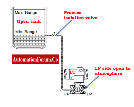
- If dust or another process condition blocks the LP side of the transmitter in this situation, Then the transmitter will indicate a level that is higher than the real level, and having the erroneous level will lead to insufficient process control.
- Check that the transmitter has been calibrated correctly.
- Check that the pressure calculations for the calibration range are correct for this application.
Troubleshooting Transmitter showing level that is lower than the real:
- While the transmitter is in operation, the equalizer in the manifold has to be kept close. The pressure will be compensated via the HP and LP side leg if it is not closed correctly. As a result, the transmitter will display a lower value than the real reading.
- Check that the transmitter has been calibrated correctly.
- Check that the pressure calculations for the calibration range are correct for this application.
- Check the process flanges for any signs of sediment.
Troubleshooting Transmitter output signal value fluctuations:
- Examine the impulse tubes for leakages. The measurement of the DP-type level transmitter might fluctuate due to tube leakage.
- If the fluctuations are particularly large, increase the damping factor in the DP-type level transmitter.
Troubleshooting Sluggish Reaction
- A possible factor is excessive damping. Verify the “Damping Adjustment” details in the transmitter manual’s Calibration section.

- Check the process tapping flanges for any signs of partial blockage in HP side.
Troubleshooting Mismatch between field and PLC/DCS flow values:
- The problem of flow value mismatch is often caused by inaccurate range setup on both sides, both in the PLC/DCS/SCADA and the field level transmitter.

- Check both the PLC/DCS/SCADA and the field level transmitter’s range.

- The level transmitter’s correct range, which should be set up on both sides, will be listed on the data sheet.