- What is Hybrid Level Measurement?
- Explaining the Hybrid Level Measurement Diagram
- Capacitance Principle in Hybrid Systems
- Working Principle of Hybrid Level Measurement
- Measuring Range of Hybrid Level Transmitters
- Handling Interfaces and Emulsion Layers
- Limitations of Hybrid Capacitance/GWR Systems
- Probe Selection Guidelines
- Installation Guidelines for Reliable Operation
- Calibration and Configuration Practices
- Troubleshooting Guide for Hybrid Systems
- Advantages of Hybrid Capacitance + GWR
- Hybrid vs Standalone GWR vs Standalone Capacitance (Comparison Table)
- Applications of Hybrid Capacitance/GWR Systems
- Best Practices for Long-Term Reliability
- Why Hybrid Capacitance + GWR is the Future
- Test your Knowledge with Advanced Quiz on RADAR Level Measurement
- FAQs on Level Measurement and Hybrid Capacitance + Guided Wave Radar (GWR)
What is Hybrid Level Measurement?
One of the most important factors in process industries is level measurement. Accurate knowledge of liquid levels inside tanks, separators, and columns is essential for safe operation, process optimization, and product quality in a variety of industries, including oil and gas production, chemical refining, and power generation.
However, when two immiscible liquids (such as water and oil) are present in the same vessel, level measurement becomes especially difficult. Additionally, between the two layers, emulsions a mixture of the two liquids frequently form, making it even more difficult for traditional measurement technologies to produce accurate readings.
This is where the industry-changing Hybrid Level Measurement system, which combines Guided Wave Radar (GWR) and Capacitance Technology, comes in. This hybrid system guarantees stable level and interface detection even under the most taxing circumstances by combining the dielectric sensitivity of capacitance with the accuracy of radar.
The hybrid level measurement principle, diagram explanation with important symbols and zones, probe measuring ranges, handling emulsion layers, benefits and drawbacks, probe selection, installation and calibration procedures, industry applications, and troubleshooting advice are all covered in this article.
Explaining the Hybrid Level Measurement Diagram
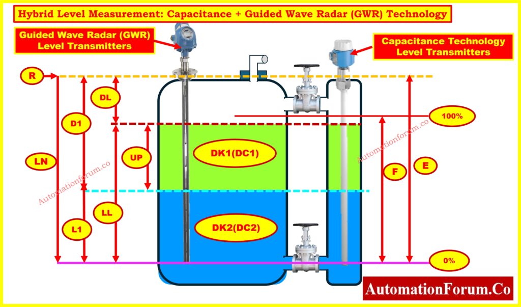
In order to measure the overall liquid level and the interface level between two immiscible liquids (such as water and oil), the above image shows how Capacitance + Guided Wave Radar (GWR) technologies are combined inside a process vessel.
Let’s break it down step by step:
GWR Principle in Hybrid Systems
These devices are mounted at the top of the tank and use microwave pulses to send signals down a probe. By identifying signal reflections brought on by a change in the dielectric constant, they are able to determine the overall liquid level (upper layer, such as oil).
Refer the below link to Explore the complete guide to GWR troubleshooting and maintenance
Capacitance Principle in Hybrid Systems
By examining the liquids’ dielectric characteristics, these probes determine the levels of interfaces (such as the oil-water boundary). This is especially helpful for finding conductive materials beneath hydrocarbons, like water.
Reference Markings in Diagram:
- R – Reference point (flange connection).
- LN – Probe length.
- DL – Distance to overall level.
- LL – Overall liquid level.
- D1 – Distance to interface level.
- L1 – Interface level.
- UP – Thickness of upper medium.
- E (0%) and F (100%) – Empty and full calibration points.
- DK1 (DC1) and DK2 (DC2) – Dielectric constants of upper and lower liquids.
In simple terms:
- GWR measures DL (overall level).
- Capacitance calculates D1 (interface level) by detecting dielectric changes.
Even in the presence of emulsions, this dual measurement guarantees accurate detection of both liquid layers.
Working Principle of Hybrid Level Measurement
Guided Wave Radar (GWR)
- Low-energy microwave pulses are sent along a probe (rod, rope, or coaxial) to operate a guided wave radar (GWR).
- A portion of the signal is reflected back when the pulse comes into contact with a boundary that has a different dielectric constant.
- The distance to the liquid surface is determined by the reflection time (time-of-flight).
- For precise single-phase measurements (such as total oil level), it performs admirably.
Refer the below link for the Understand Doppler effect frequency shift free calculator in radar transmitters
Capacitance Measurement
- uses the liquid as the dielectric medium and the probe as one of the capacitor’s plates.
- The dielectric constant and liquid height have an impact on the measured capacitance.
- especially useful for identifying liquid-to-liquid interfaces (such as water/oil).
The Hybrid Advantage
- GWR: Precise detection of the overall level.
- Capacitance -Even with emulsions, capacitance provides a dependable interface measurement.
- Together – When combined, hybrid systems address the shortcomings of stand-alone technologies.
Measuring Range of Hybrid Level Transmitters
The range and applicability are determined by various probe designs:
| Probe Type | Typical Measuring Range | Best Application |
| Rod Probe | ≤ 4 m (13 ft) | Short-to-medium tanks, chambers |
| Rope Probe | ≤ 10 m (33 ft) | Tall process vessels |
| Coaxial Probe | ≤ 6 m (20 ft) | High accuracy in challenging conditions |
- Rod probes are small and ideal for small vessels or chambers.
- Rope Probes: When rods are impractical, use rope probes to handle taller tanks.
- Coaxial Probes: Coaxial probes are perfect for non-metallic vessels or noisy environments because they offer exceptional signal stability.
Learn step-by-step methods to fix radar level transmitters: Step-by-Step Guide for Troubleshooting Radar Level Transmitters
Handling Interfaces and Emulsion Layers
The hybrid system’s true strength lies in its ability to detect interfaces.
Clear Interface:
- GWR gauges the general level, such as that of oil.
- The interface (oil/water boundary) is measured by capacitance.
Emulsion Present:
- Because radar signals are scattered or absorbed, traditional GWR frequently fails.
- By examining the liquids’ dielectric values, capacitance makes up for it.
- Result: Although precise emulsion thickness may not be measurable, the hybrid system still offers trustworthy oil + water level detection.
Outcome: Even in challenging emulsion conditions, hybrid systems produce reliable results in water treatment facilities, refinery desalters, and oil-water separators.
Check essential installation checklist for guided wave radar: Guided Wave Radar Level Transmitter Installation Checklist
Limitations of Hybrid Capacitance/GWR Systems
- Dielectric Dependency: Variations in the dielectric constant determine measurement accuracy; abrupt changes can compromise dependability.
- accumulation Sensitivity: Probe coating made of sticky or viscous materials may alter capacitance response and necessitate regular cleaning.
- Foam & Vapor Interference: Signal clarity may be distorted by excessive foam, variations in vapor density, or turbulence.
- High-Pressure Constraints: Capacitance probes may not be able to withstand high pressure ranges, even though GWR manages pressure well.
- Temperature Influence: Significant temperature variations may cause capacitance readings to change, necessitating recalibration or compensation.
- Maintenance Requirement: To prevent drift and guarantee that the capacitance and GWR channels remain aligned, combination probes require appropriate maintenance.
- Compared to stand-alone level measurement technologies, the initial cost is higher.
- Complexity in Hazardous Areas: For explosive or high-safety zones, careful certification and installation are necessary.
Probe Selection Guidelines
- Media Characteristics: Select the type of probe by considering the density, conductivity, viscosity, and liquid dielectric constant.
- Tank Dimensions: Make sure the probe length is appropriate for the vessel’s geometry to prevent contact with internal obstructions.
- Interface Measurement: When precise interface and total level are needed, choose dual-mode probes.
- Temperature & Pressure Rating: Verify that the sealing and probe materials correspond to the operating conditions of the process.
- Corrosion Resistance: To avoid damage from aggressive chemicals, use coated probes, PFA, or PTFE.
- Mounting Flexibility: Depending on the height of the tank and the accessibility of the nozzle, choose rigid or flexible probes.
- Process Disturbances: Use the probe in bypass chambers or stilling wells for agitated or turbulent liquids.
- Hazardous Area Compliance: Verify that the electronics and probe type satisfy any necessary ATEX, IECEx, or FM approvals.
Installation Guidelines for Reliable Operation
- Nozzle Positioning: To minimize false reflections, place probes away from tank walls, agitators, and inlet streams.
- Grounding: To reduce electrical noise and ensure accurate capacitance, make sure the grounding is done correctly.
- Probe Clearance: To avoid signal distortion, keep as far away from metallic objects inside the tank as possible.
- Stilling wells are advised for applications involving foam or turbulence in order to stabilize measurement signals.
- Orientation: For GWR accuracy, place probes vertically; slanted mounting lowers signal quality.
- Gaskets and Sealing: To prevent chemical reactions or leaks, use sealing materials that are compatible with your process.
- Cable Routing: To minimize interference, keep signal cables protected and away from high-power electrical lines.
- Testing Following Installation: Use a sight glass or manual dip measurement to confirm readings for baseline validation.
Calibration and Configuration Practices
- Although many hybrid systems are pre-configured, site calibration might still be necessary.
- Adjust the zero and span to make sure the calibration corresponds to the full and empty reference levels of the tank.
- Dielectric Compensation: If process fluids change over time, configure the device to account for dielectric variations.
- Interface Tuning: Adjust GWR for top-level tracking and capacitance for interface detection using hybrid features.
- Temperature Compensation: Allow for automatic adjustment of capacitance shifts caused by temperature.
- Diagnostics & Self-Check: To identify coating issues, signal loss, or probe malfunctions, use the integrated diagnostics.
- Data Integration: To ensure smooth DCS/PLC communication, configure output signals (4-20 mA, HART, Profibus, Foundation Fieldbus).
- Periodic Verification: To guarantee long-term dependability, recheck calibration during planned maintenance.
Gain insights into calibration and care of capacitance transmitters: Calibration, Troubleshooting and Installation of Capacitance Type Level Transmitter
Troubleshooting Guide for Hybrid Systems
| Issue | Possible Cause | Recommended Action |
| Erratic or no signal | Poor grounding or EMI interference | Check probe grounding, shield cables, and reduce electrical noise sources |
| Inaccurate readings in foamy media | Foam attenuates radar reflections | Use stilling wells or enable advanced filtering in GWR settings |
| Sudden level drift | Probe coating, fouling, or build-up | Inspect and clean probe; verify capacitance recalibration |
| Weak radar echoes | Low dielectric constant of liquid | Increase radar sensitivity or rely more on capacitance correction |
| Signal loss at high temperature/pressure | Probe rating exceeded | Confirm probe design matches process; upgrade to high-spec probe |
| Interface measurement failure | Insufficient dielectric contrast between liquids | Recalibrate hybrid mode; verify upper and lower dielectric values |
| Device shows alarm/fault | Internal diagnostics triggered | Use transmitter diagnostics to isolate whether radar or capacitance channel failed |
| Integration issues with PLC/DCS | Wrong scaling or communication mapping | Recheck 4-20 mA/HART/Fieldbus configuration and DCS mapping |
| Frequent recalibration required | Process instability (e.g., variable dielectric, turbulence) | Enable compensation settings; use stilling chambers if needed |
| Validation doubts | Lack of cross-check | Compare readings with manual dip/sight glass during inspections |
Discover how capacitance converts into accurate level readings: Capacitance to Level Conversion Calculator for Level Transmitters
Advantages of Hybrid Capacitance + GWR
- Dual Technology Assurance: By combining capacitance and radar, Dual Technology Assurance ensures dependable operation even in the event that one signal deteriorates..
- Improved Accuracy: Improved performance in difficult situations such as emulsions, foams, and low dielectric media.
- Interface & Level in One Device : This device measures the interface level and the overall tank level simultaneously.
- Decreased Process Downtime: Redundancy reduces the likelihood of unplanned failures.
- Wider Application Range: Water-based liquids, chemicals, slurries, and hydrocarbons can all be used with it.
- Robust in Harsh Environments: Able to withstand high temperatures, high pressures, and corrosive service conditions.
- Cost Optimization Over Time: Longer probe life, improved reliability, and fewer shutdowns offset higher initial costs.
- Smart Diagnostics: Predictive maintenance alerts are integrated into modern devices to enhance asset management.
- Flexible Communication: Able to integrate into contemporary control systems using a variety of digital communication protocols.
- Future-Proof Design: Suitable for IIoT applications, allowing for remote analytics and monitoring.
Master principles and troubleshooting of capacitance level transmitters: Principle, Installation and trouble shooting of capacitance type level transmitter
Hybrid vs Standalone GWR vs Standalone Capacitance (Comparison Table)
| Feature / Criteria | Hybrid (Capacitance + GWR) | Standalone GWR | Standalone Capacitance |
| Measurement Principle | Combines guided radar reflections + dielectric capacitance sensing | Time-of-flight radar reflection along probe | Change in capacitance relative to dielectric constant |
| Accuracy | Very high, redundancy ensures stable reading | High, especially in clean, low-foam media | Moderate, influenced by dielectric changes |
| Interface Detection | Excellent – can measure both interface & total level | Limited – interface detection less reliable | Good for liquids with stable dielectric contrast |
| Performance in Low Dielectric Media | Reliable (GWR covers weak capacitance signals) | Can struggle if dielectric is too low | Poor – highly dependent on dielectric constant |
| Effect of Build-up / Coating | Mitigated (GWR compensates when capacitance drifts) | Can affect signal reflection | Major impact – requires frequent cleaning |
| Pressure & Temperature Handling | Wide range, depends on probe design | Very good (handles extremes well) | Limited, not always suitable for high pressure/temperature |
| Maintenance Needs | Moderate – requires periodic calibration and inspection | Low – minimal calibration required | High – frequent recalibration needed |
| Cost | Higher upfront, but reduces downtime | Moderate | Low initial cost, but higher lifecycle maintenance |
| Best Applications | Harsh conditions, emulsions, foamy or sticky media, interface + total level | General-purpose level in liquids, high-pressure/temperature tanks | Simple applications with stable, clean, single-phase liquids |
Refer the below link for the Displacer type interface level transmitter dry calibration weight calculator
Applications of Hybrid Capacitance/GWR Systems
- Oil-water separator interface measurement.
- monitoring the level in storage tanks with different dielectric characteristics.
- ideal for difficult process conditions, such as foams or emulsions.
- utilized in power generation facilities, chemical plants, and refineries.
Best Practices for Long-Term Reliability
- Inconsistent readings: Look for probe fouling.
- Verify the dielectric constants if there is no interface detection.
- Noisy signals: Avoid agitator zones and strengthen grounding.
- Check the dielectric entries again for calibration drift.
Why Hybrid Capacitance + GWR is the Future
One of the most dependable methods for contemporary process industries is Hybrid Level Measurement using Capacitance + Guided Wave Radar (GWR). Even in cases where emulsions make measurement more difficult, it provides precise overall level and interface detection by fusing the accuracy of radar with the dielectric sensitivity of capacitance.
Excellent performance is ensured by careful probe selection, proper installation, and proper calibration, despite certain limitations with regard to dielectric ranges and probe fouling.
Hybrid Capacitance/GWR technology is quickly taking over as the industry standard for oil-water interface measurement, desalters, separators, and chemical process units due to industry demands for increased accuracy, safety, and efficiency.
Refer the Following link for calibration steps for precise capacitance level measurement
Test your Knowledge with Advanced Quiz on RADAR Level Measurement
Refer the below link to test expertise with our Advanced Quiz on RADAR Level Measurement for Process Instrumentation Engineers
FAQs on Level Measurement and Hybrid Capacitance + Guided Wave Radar (GWR)
What are the different types of level measurements?
Depending on the application, level measurements can be made directly (using sight glasses or floats) or indirectly (using hydrostatic pressure, capacitance, ultrasonic, radar, GWR, nuclear, and hybrid systems)..
What is the hydraulic method of level measurement?
The hydraulic method uses a pressure balance system to determine the liquid level. Level is indicated by the differential pressure, which is balanced against the liquid column by a connected pressure line.
What is the Hydra step method of level measurement?
Several probes are used in the capacitance-based Hydra step method to measure the water-steam ratio in boilers. For precise drum level monitoring, it offers distinct steps.
What is the hydrostatic method of level measurement?
The idea that liquid pressure at a depth is proportional to liquid height and density is the basis for the hydrostatic method. For this technique, differential pressure transmitters are frequently employed.
What is hybrid level measurement in process industries?
Even in emulsions, hybrid level measurement reliably measures both the overall liquid level and the interface level by combining Guided Wave Radar (GWR) and Capacitance technologies.
Why use hybrid Capacitance + GWR instead of standalone transmitters?
Redundancy is provided by hybrid transmitters. Capacitance provides precise interface detection, while GWR guarantees accurate total level. For emulsions and oil-water separators, this combination is perfect.
Can hybrid GWR-capacitance transmitters work in foamy or turbulent tanks?
Yes. Stable operation in turbulent or foamy process conditions is made possible by capacitance correction, coaxial probes, and stilling wells.
Where are hybrid level measurement systems used?
For precise interface detection, they are extensively utilized in petrochemical facilities, power generation, desalters, oil and gas separators, and chemical processing units.
How do emulsions affect level measurement and how does hybrid solve this?
Radar signals are scattered by emulsions, rendering standalone GWR unreliable. Reliable interface measurement is ensured by the capacitance channel compensating by detecting dielectric differences.
 transmitters improve liquid level and interface detection in tanks, separators, and emulsions)