- What is a Liquid Interface?
- Understanding Emulsions (Rag Layers)
- Step-by-Step Interface Level Measurement Selection Procedure
- Interface Level Measurement Technology Comparison Table
- Calibration & Commissioning Guidelines
- Regulatory Standards & Compliance
- Technology-by-Technology Analysis
- Best Practices for Interface Level Measurement
- Maintenance & Life Cycle Costing
- Common mistakes in interface level measurement Selection
- Troubleshooting Common Issues
- Recommendations & Safety Instrumented Functions
- Environmental & Energy Considerations
- Interface Level Measurement Selection Checklist – Download
- FAQ on Interface level measurement
- Test your knowledge on Level Measurement
Importance in Industrial Processes
In sectors like oil and gas, refining, petrochemicals, power generation, mining, and water treatment, measuring the interface level is a very important process parameter. Finding and controlling the exact point where two immiscible phases, like oil and water, separate is important for making sure that the process runs smoothly, the result is of high quality, and safety rules are followed.
Risks of Incorrect Selection
Choosing the wrong thing might lead to incorrect readings, unexpected shutdowns, product contamination, and even safety risks. This article informs you what a liquid interface is, what problems emulsions might cause, and how to choose the correct level measurement technology in a step-by-step way.
We will also provide a comparison chart that shows how well each technology works in common oil-water interface situations and go into further detail about the benefits and cons of each one.
What is a Liquid Interface?
Oil-Water Separation Examples
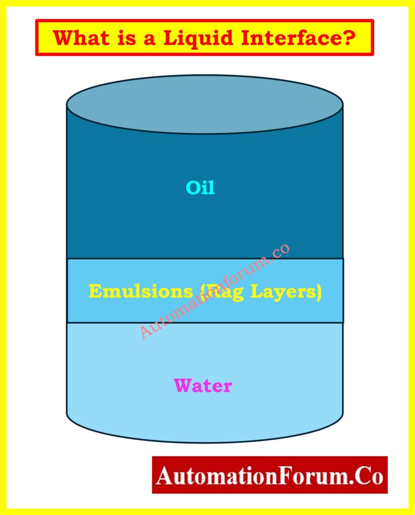
A liquid interface is the line that separates two liquids in a tank or vessel that don’t mix and have different densities.
- The heavier liquid (with a higher specific gravity) naturally falls at the bottom.
- The liquid that is lighter floats on top.
Role of Density & Stability in Measurement
For instance:
- In a three-phase separator at an oil production site, gas is on top, oil is in the center, and water is at the bottom.
- In a desalting unit in a refinery, crude oil floats on top of the water that is used to wash away the salts.In a desalting unit in a refinery, crude oil floats on top of the water that is used to wash away the salts.
Key consideration: The sharper and more stable the interface is, the easier it is to measure. Choosing a measurement technology is harder if the contact is unstable because of turbulence or emulsions.
Understanding Emulsions (Rag Layers)
Types of Emulsions (Oil-in-Water, Water-in-Oil)
An emulsion, sometimes known as a rag layer, is a mix of two liquids that don’t mix well, with droplets of one phase spread out in the other.
In oil-water separation:
- Oil-in-water emulsion: Water holds oil droplets in place.
- Water-in-oil emulsion: Water droplets are suspended in oil.
Why Rag Layers Affect Accuracy
- The density fluctuates slowly along the layer, which makes it hard for density-based tools like DP transmitters or displacers to work.
- The dielectric constant also fluctuates over time, which makes radar-based tools lose signal strength.
- The thickness of the rag layer might change a lot depending on the temperature, flow velocity, and chemicals used.
For instance, a thick rag layer can show up in a production separator when it first starts up or after a sudden increase in production flow. This makes some interface monitoring methods unreliable unless they can manage this situation.
Step-by-Step Interface Level Measurement Selection Procedure
When choosing a transmitter, it’s not just about picking the newest technology; it’s also about making sure the measuring principle fits the process conditions.
Here’s the seven-step approach:
Step 1: Define the Process Requirement
- Is the measurement continuous (for control loops) or point-based (for alarms and interlocks)?
- Is the purpose inventory monitoring, process control, or safety shutdown?
- What is the accuracy requirement? ±2 mm may be needed for custody transfer; ±25 mm may be sufficient for process control.
Step 2: Identify Fluid Properties
- Densities: The greater the difference, the easier for density-based technologies (DP, displacer).
- Dielectric constants: For radar-based systems, a dielectric constant difference >10 is preferred.
- Conductivity: Capacitance systems need both a conductive and a non-conductive liquid.
- High viscosity can trap bubbles or solids, which can change the measurement.
- Color and opacity are important for optical systems, but this table doesn’t address them.
Step 3: Evaluate Operating Conditions
- Pressure: Some tools need chambers or probes to have certain pressure ratings.
- Temperature: Very high or very low temperatures might affect the choice of materials and how well sensors work.
- Vibration and turbulence may need stilling wells or bypass chambers.
- Corrosive service: Pick materials and coatings that won’t be harmed by chemicals.
Step 4: Assess Installation Constraints
- Nozzle size and location: Wave Guide Radar probes need a long enough straight insertion length.
- Availability of bypass chambers: Displacers and GWR typically need side chambers.
- Obstructions inside: Agitators or pipes within can get in the way of free-space radar.
Step 5: Consider Emulsion Layer
- Thin emulsions (< 2 inches): Many radar and GWR systems can still detect the interface.
- Thick emulsions: Density or dielectric contrast is reduced consider hybrid or nucleonic systems.
Step 6: Shortlist Technologies using Table
Use the suitability table to narrow down possible options before deeper evaluation.
The following table compares Differential Pressure (DP), Displacer, Radar, Guided Wave Radar (GWR), Capacitance, Hybrid Capacitance/GWR, and Nucleonic technologies for common oil-water applications.
Step 7: Final Selection
- Match technology to budget, maintenance requirements, and regulatory compliance.
- Dual-technology systems (like Hybrid Capacitance/GWR) make crucial operations more reliable.
Interface Level Measurement Technology Comparison Table
| Level Measurement | DP | Displacer | Radar | GWR | Capacitance | Hybrid Capacitance/GWR | Nucleonic |
| Oil-gas Interface | Suitable | Suitable | Suitable | Suitable | Not Suitable | Suitable | Suitable |
| Clean Oil-water interface | Suitable | Suitable | Not Suitable | Suitable | Suitable | Suitable | Suitable |
| Oil-water with important emulsion | Not Suitable | Not Suitable | Not Suitable | Not Suitable | Partially Suitable | Partially Suitable | Suitable |
| Liquid-liquid with small emulsion layer | Suitable (loss of accuracy) | Suitable (loss of accuracy) | Not Suitable | Not Suitable | Suitable | Suitable | Suitable |
| Solid deposit + liquid/foam | Not Suitable | Not Suitable | Not Suitable | Not Suitable | Not Suitable | Not Suitable | Suitable |
Learn How to Measure Interface Level with a Remote Seal DP Transmitter: Interface level measurement using DP transmitter (Remote sealed)
Calibration & Commissioning Guidelines
- If feasible, do wet calibration at the actual process density.
- When you can’t recreate the process conditions, use simulation tools or reference devices.
- Check that the installation satisfies the manufacturer’s criteria for probe length, chamber orientation, and clearance.
- Write down the baseline readings so you can fix problems later.
Regulatory Standards & Compliance
Always make sure that the interface measuring technology you choose meets industry standards (such API MPMS, IEC 60079, and ISO 5167) and local hazardous area classifications (like ATEX, IECEx, FM, and CSA). In the oil and gas and chemical industries, you usually have to get certified before you can install something.
Technology-by-Technology Analysis
1. Differential Pressure (DP) Transmitters
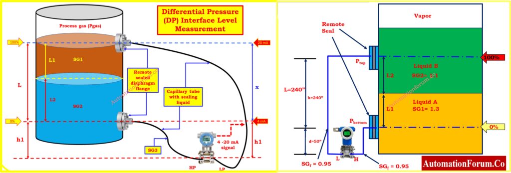
- Working Principle: It measures the difference in hydrostatic pressure between two places that are at different heights..
- Advantages: Benefits: easy to use, cheap, and well-known.
- Limitations: The accuracy goes down when the density difference is tiny or changes with temperature; it doesn’t work well with thick emulsions.
- Example Application: Clean the oil-water contact in a separator with constant densities.
Calculate DP for Interface Level Measurement Instantly: DP calculator for Interface level measurement
2. Displacer
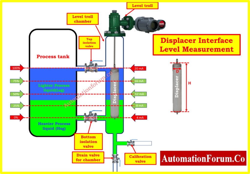
- Working Principle: Detects buoyant force changes on a suspended element as liquid density changes.
- Advantages: Proven mechanical method; suitable for stable interfaces.
- Limitations: Mechanical wear; affected by density changes; unsuitable for thick emulsions.
- Example Application: Side-chamber-mounted displacer in a refinery desalting unit.
3. Radar (Non-Contact)
- Working Principle: It sends out microwaves and measures the time it takes for them to bounce off the surface.
- Advantages: Doesn’t touch anything; not influenced by pressure or temperature; great for oil-gas interfaces.
- Limitations: Doesn’t work well with emulsions; needs a distinct dielectric difference.
- Example Application: Gas-oil separation in a vertical separator is an example of how this can be used.
Master Guided Wave Radar Troubleshooting & Maintenance: Guided Wave Radar Level Transmitters: Complete Troubleshooting & Maintenance Guide
4. Guided Wave Radar (GWR)
- Working Principle: It sends radar pulses along a probe to find both the top and interface levels.
- Pros: It can measure both the top and the interface of a liquid, it isn’t affected by density, and it operates in small spaces.
- Limitations: Needs a dielectric difference of more than 10; thick emulsions block signals.
- Example Use: The oil-water contact in a horizontal separator with a thin layer of rags.
Follow the Guided Wave Radar Installation Checklist for Accurate Readings: Guided Wave Radar Level Transmitter Installation Checklist
5. Capacitance
- Working Principle: Measures how the capacitance between a probe and the tank wall changes when the media changes.
- Pros: Works well with emulsions and doesn’t care about density.
- Limitations: needs a pair of conductive and non-conductive liquids; is sensitive to variations in conductivity.
- Example use: Finding out how much water is below the oil in storage tanks..
6. Hybrid Capacitance/GWR
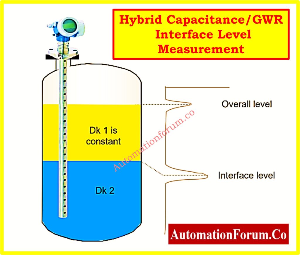
- Working Principle: The working principle is that it uses both GWR and capacitance for redundancy and shifts between them based on the characteristics of the emulsion.
- Pros: Can handle changing process conditions; works well with emulsions that change.
- Limitations: More expensive and more complicated.
- Example Application: Offshore separators with changing production chemistry.
Find the Exact Dry Calibration Weight for Your Displacer Interface Level Transmitter
7. Nucleonic
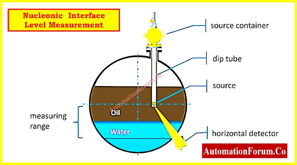
- Working Principle: This device works by using gamma radiation attenuation to find changes in density through the walls of a vessel.
- Benefits: It works in any situation and is not affected by emulsions, solids, foam, or deposits.
- Limitations: High cost and rigorous rules from the government.
- Example Use: Processing heavy oil with thick rag layers and solids.
Explore 15+ Powerful Level Measurement Calculators for Instrument Engineers: 15+ Collection of Level Measurement Calculators for Industrial Instrumentation
Best Practices for Interface Level Measurement
- Calibrate in real-world situations: Values for density in the lab and in the process are often different.
- Use wells that are still: Lower turbulence and make signals more stable for radar and capacitance.
- Systems that are not needed: Put in both a primary and a backup measurement technique in crucial separators.
- Cleaning the probe on a regular basis: Stops coating from changing capacitance and radar signals.
- Keeping an eye on trends: Keep an eye on how the emulsion behaves over time to find any unusual process circumstances.
Maintenance & Life Cycle Costing
- Set up regular cleanings of probes, chambers, and stilling wells to keep coatings from building up.
- Look at the costs of the life cycle Not just the amount you pay up front, but also the cost of spare parts, how often you need to calibrate, and the hazards of downtime.
- Use smart transmitters with condition monitoring tools to find performance drift early..
Common mistakes in interface level measurement Selection
- Choosing based only on cost: If a cheaper technology doesn’t work in real-world situations, it will cost more in downtime.
- Ignoring possible emulsions: Rag layers might show up at random times, especially in production separators and desalters.
- Not paying attention to nozzle limits: It may be the best technology, but it may not be practical to implement it.
- Not taking into account modifications to the process in the future: The qualities of oil, how chemicals are used, and how much oil is processed can all change over time.
Troubleshooting Common Issues
- Coating or scaling can weaken radar and capacitance signals. To fix this, clean them often or use anti-coating products.
- To stop foam from forming, put in stilling wells or bypass chambers to stabilize the measurement.
- If there are signal dropouts, check the grounding, cable shielding, and dielectric discrepancies.
- Different types of emulsions: If your emulsions change thickness often, switch to hybrid or nucleonic.
Recommendations & Safety Instrumented Functions
No one measurement technology works perfectly for all types of interfaces. What you choose depends on:
- Liquid qualities, such as density, dielectric, and conductivity
- Conditions of the process (pressure, temperature, existence of emulsion)
- Installation limits
- Requirements for safety and accuracy
Data Integration & Digital Communication
HART, Foundation Fieldbus, and WirelessHART are just a few of the protocols that modern interface measurement transmitters can use. These allow:
- Setting parameters from a distance.
- Checks for problems in real time.
- Integration with DCS/SCADA for predictive maintenance and trending.
Safety Instrumented Function (SIF) Considerations
Check the SIL (Safety Integrity Level) standards in IEC 61511/IEC 61508 if the interface measurement is part of a safety shutdown system. You might need to do further measurements (1oo2 or 2oo3) to get the safety integrity you need.
All of the following systems perform well for clean oil-water interfaces: DP, Displacer, GWR, Capacitance, and Hybrid.
For thick emulsions, only Nucleonic and some capacitance/hybrid configurations can give you readings that you can trust.
For vessels that are hard to reach or are in bad shape, Nucleonic is the most reliable option, but it is also the most expensive.
When processes are high-risk and high-cost, you should think about using redundant systems.
In some circumstances, dual technology like Hybrid Capacitance/GWR is the optimum choice because it gives you both redundancy and protection against changes in the process.
Environmental & Energy Considerations
Think about insulating the process to keep the temperatures steady and stop the measurements from drifting.
To limit radiation exposure in nucleonic systems, use the ALARA (As Low As Reasonably Achievable) rules.
Choose materials and seals that are good for the environment and last a long time.
Interface Level Measurement Selection Checklist – Download
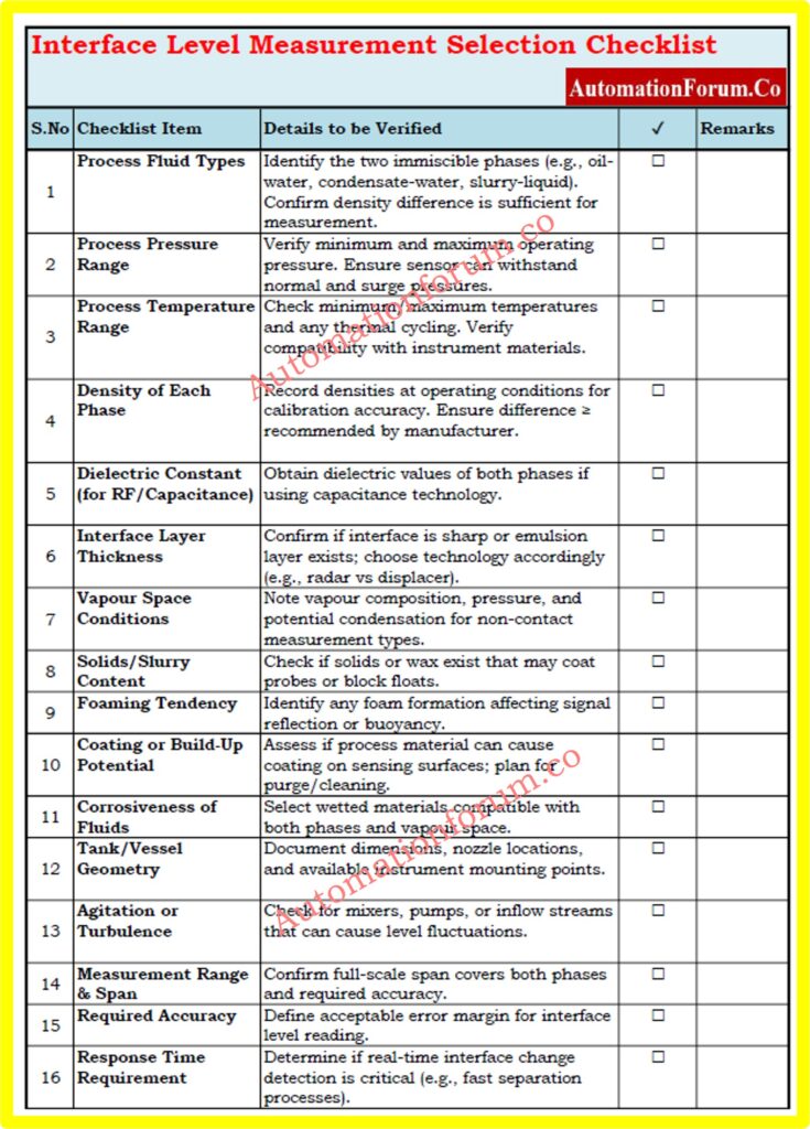
Choosing the correct interface level measurement instrument is important for making sure that industrial liquid-liquid separation processes are accurate, safe, and efficient. To get the checklist, click on the link below.
Interface Level Measurement Selection Checklist – Download
By following the seven-step selection procedure and using table as a quick reference, engineers can make a confident, technically sound decision ensuring measurement accuracy, process stability, and operational safety.
FAQ on Interface level measurement
What is interface level measurement?
Interface level measurement is the process of detecting the separation point between two immiscible liquids, such as oil and water, in a vessel or separator. It ensures efficient separation, quality output, and process safety.
Which technology is best for oil-water interface measurement?
For clean oil-water interfaces, Guided Wave Radar (GWR), DP transmitters, capacitance, and hybrid systems perform well. For thick emulsions, nucleonic measurement or hybrid capacitance/GWR offers more reliable results.
How do emulsions affect interface measurement accuracy?
Emulsions create gradual density or dielectric changes, making it harder for density-based and radar systems to detect a clear boundary. They can cause signal attenuation and fluctuating readings.
What factors should be considered when selecting an interface level transmitter?
Key factors include fluid densities, dielectric constants, conductivity, operating temperature, pressure, presence of emulsions, nozzle size, installation constraints, and safety requirements.
How often should interface level measurement instruments be calibrated?
Calibration frequency depends on process criticality, but for high-accuracy or safety-critical applications, annual calibration or verification during shutdowns is recommended.
Test your knowledge on Level Measurement
Refer the below link to test your expertise in level measurement technologies