- Understanding the Difference Between Junction Box, Marshalling Panel, and System Cabinet
- What is a Junction Box in Instrumentation?
- What Is a Marshalling Panel in Instrumentation?
- What Is a System Cabinet in DCS and PLC Systems?
- How Signal Travels from Field Instrument to Operator Station
- Marshalling Panel vs Junction Box vs System Cabinet
- How EPC Engineers Select the Right Enclosure
- Common Engineering Mistakes in Signal Routing Architecture
- FAQs on Marshalling Panel vs Junction Box vs System Cabinet
- What is the difference between a Junction Box and a Marshalling Panel ?
- What does a Marshalling Panel do in instrumentation ?
- What is the function of a System Cabinet ?
- Why is cross wiring used in marshalling ?
- Can a Junction Box contain active control hardware ?
- What signals are normally routed through a Marshalling Panel ?
- Why are System Cabinets used in DCS and PLC systems ?
- How do EPC engineers decide between direct wiring and marshalling ?
- What is the role of shielding in these enclosures ?
- What are the common mistakes in signal routing architecture ?
- Best Practices for Instrumentation Projects
- Conclusion: Final Takeaway for EPC and Instrumentation Engineers
Understanding the Difference Between Junction Box, Marshalling Panel, and System Cabinet
In instrumentation and control projects, many engineers use the terms Junction Box, Marshalling Panel, and System Cabinet as though they mean the same thing. They do not. Each enclosure has a distinct role in the signal chain, and each one affects cabling, commissioning, troubleshooting, cost, and maintainability in a different way.
Why Junction Boxes, Marshalling Panels, and System Cabinets Are Not the Same
A Junction Box is mainly a field termination point. A Marshalling Panel is a signal routing and organization point. A System Cabinet is the home of active automation hardware such as PLCs, DCS controllers, I O cards, communication modules, power supplies, and network devices.
Impact of Signal Routing Architecture on EPC Instrumentation Projects
When these roles are not understood clearly, the project suffers. Cable schedules become confusing. Loop checks take longer. The signal is hard to trace. Maintenance crews have a hard time locating an issue. EPC teams also face repeated drawing revisions and unnecessary rework.
Typical Signal Flow in a Process Plant Automation System
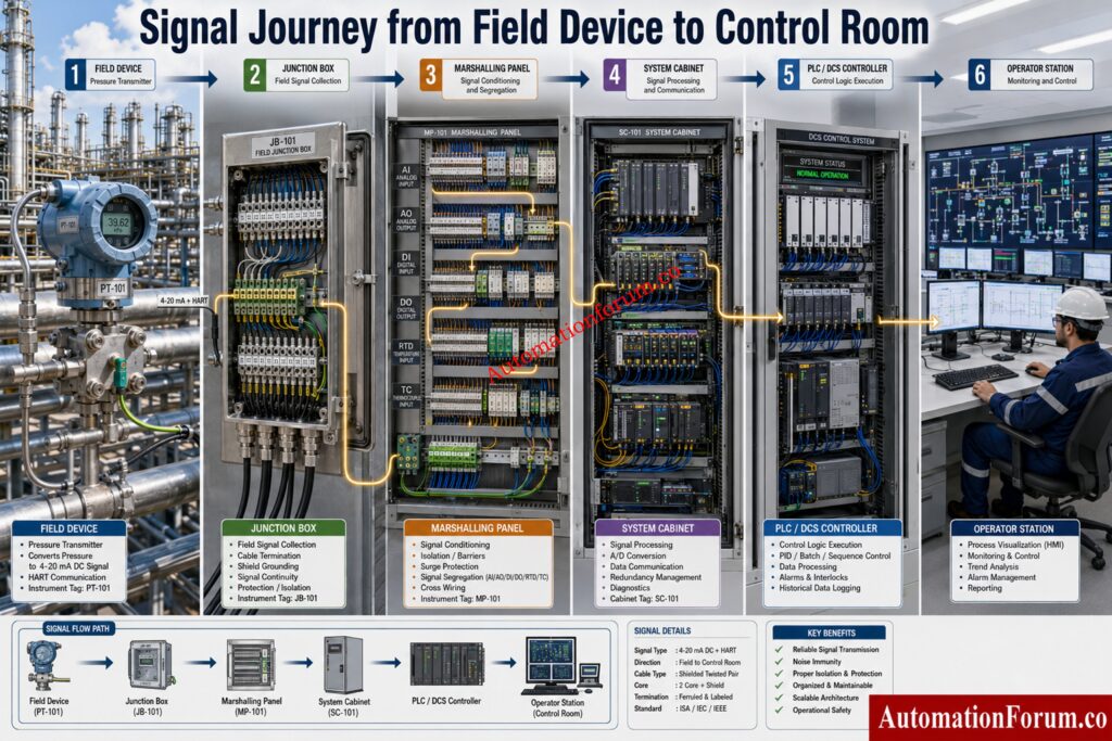
In a typical process plant, the signal path often follows this order:
- Field instrument
- Junction Box
- Marshalling Panel
- System Cabinet
- DCS or PLC Controller
- Operator Station
Importance of Structured Signal Architecture in Industrial Automation
That architecture remains fundamental in large automation projects because it creates traceability, order, and reliability across the entire instrumentation system.
Avoid Costly Commissioning Delays With These Proven Checks: Factory Acceptance Test (FAT) Procedure & Checklist for Marshalling Cabinets
What is a Junction Box in Instrumentation?
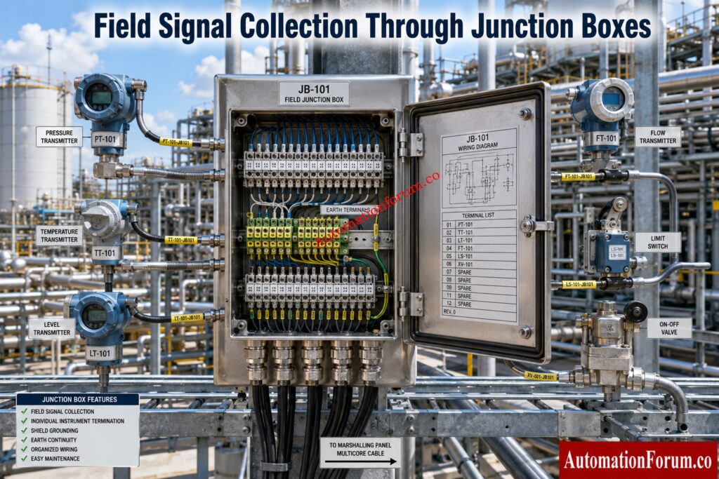
A Junction Box is a passive container for terminating and collecting field wiring from equipment in the plant area. It is designed to protect terminations and simplify the transition from individual field cables to multicore cables or trunk cables.
A Junction Box is a termination enclosure used for local field wiring consolidation. It does not process signals. It does not perform logic. It does not contain controller hardware.
What Is the Purpose of a Junction Box?
Its main purpose is to make field wiring practical and safe. Instead of running every instrument cable all the way to the control room, engineers can collect nearby instrument wiring in one enclosure and then route that wiring more efficiently.
What Are the Internal Components of a Junction Box?
Types of Junction Boxes Used in Process Plants
There are several common types.
- Instrumentation Junction Box For transmitters, switches, and valve instrumentation
- Power Junction Box For power distribution applications
- Hazardous Area Junction Box: Used in classified areas where safety and certification are necessary
- Weatherproof Junction Box: Applications requiring dust and moisture protection
- Explosion Proof Junction Box: For use where the environment may be ignitable and enclosure integrity is important
Where Junction Boxes Are Installed in Industrial Projects
Junction boxes are commonly utilized in process facilities, utilities, remote field locations, tank farms, pipe racks and skid mounted systems.
Advantages and Limitations of a Junction Box
A Junction Box provides easier installation, minimizes local cable clutter and helps organize field termination. It also helps shorten individual cable runs from instruments to the first termination point.
A Junction Box is only a termination point. It cannot organize signals by I O type, it cannot perform cross wiring, and it cannot replace marshalling. It also cannot host active control hardware.
Real Field Example
If several pressure transmitters are installed around a storage tank, their individual cables may first arrive at a local Junction Box. From there, a multicore cable can carry the collected signals to the marshalling area. This arrangement reduces cable complexity in the field and keeps the wiring more orderly.
Refer the below link for the JB Grouping in Industrial Automation and Instrumentation – Complete Practical Guide for EPC, Site and Commissioning Engineers
What Is a Marshalling Panel in Instrumentation?
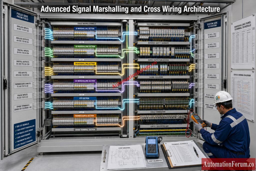
A Marshalling Panel is the organized signal routing point between field terminations and the control system. It is where incoming signals are redistributed so they match the layout and channel order of the DCS or PLC system.
A Marshalling Panel is a signal arrangement enclosure used to receive field wiring and route it toward the correct control system inputs and outputs.
Why Marshalling Panels Are Used in EPC Projects
Field wiring is arranged by physical location, equipment grouping, or cable pull convenience. Control system wiring is arranged by I O card type, signal type, loop design, and system architecture. These two arrangements usually do not match. Marshalling exists to bridge that gap.
What Is Signal Marshalling?
The purpose of marshalling is to sort, segregate, identify, and route each signal correctly. It also allows a design team to separate analog, digital, RTD, thermocouple, pulse, and special purpose circuits in a disciplined way.
A good marshalling design creates a clear path from the field side to the control side. It reduces confusion during commissioning and supports long term maintenance. It also allows engineers to trace every loop from field device to controller channel.
Strengthen Functional Safety Compliance With Expert Checks: Advanced Safety Instrumented System (SIS) Inspection Checklist for IEC 61511 Compliance
Cross Wiring Concept in a Marshalling Panel
Cross wiring is the practice of taking a field side termination and connecting it to a different outgoing termination that matches the controller or I O system requirement. This is essential when field cable order does not match control system card order.
Signal Segregation in Marshalling Panels
A robust marshalling panel keeps the following signal groups properly separated:
- Analog Inputs
- Analog Outputs
- Digital Inputs
- Digital Outputs
- RTD signals
- Thermocouple signals
- Pulse signals
This separation reduces noise problems, avoids wiring errors, and makes troubleshooting much easier.
Prevent Grounding Issues That Damage Instrument Signals: Single Point vs Multiple Point Grounding in Instrumentation Systems: Complete Guide for Engineers
Internal Components of a Marshalling Panel
Typical Marshalling Layout
The incoming side receives field cables or cables from Junction Boxes. The outgoing side sends organized signals toward the system cabinet or controller I O arrangement. Each signal should be traceable through the panel without ambiguity.
Signal Routing Examples
A pressure transmitter may terminate first in a Junction Box, then in the marshalling panel, and then continue to an analog input card in the system cabinet.
A valve solenoid may follow a similar path but land on a digital output card.
An RTD may be routed with careful attention to conductor grouping and signal integrity.
Marshalling Panel Design Considerations
A good marshalling panel design must consider signal count, spare capacity, future expansion, intrinsic safety separation, shield grounding, cable density, terminal accessibility, and maintenance clearance.
Maintenance Considerations
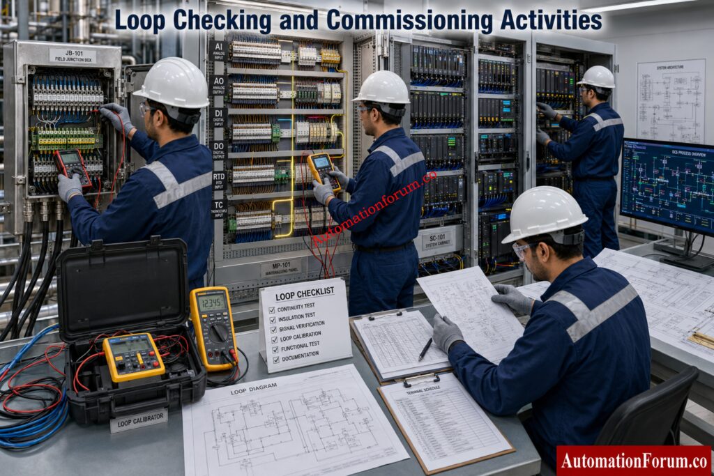
When a loop fails, the marshalling panel is often the best place to isolate the fault. Maintenance teams can check field integrity, cable continuity, barrier condition, and outgoing system side wiring from this single point.
Commissioning Perspective
Commissioning teams use marshalling panels to verify cable numbers, terminal tightness, shield landing, polarity, continuity, and signal routing before live operation begins.
Advantages and Limitations of a Marshalling Panel
Marshalling improves traceability, supports orderly testing, simplifies expansion, and helps the commissioning team verify loops one by one.
A marshalling panel adds cost, occupies space, and increases the number of terminations. That means workmanship, documentation, and labeling must be excellent.
Real EPC Project Example
In a large process unit, many Junction Boxes may feed one marshalling panel. From there, signals are redistributed to the correct DCS I O channels. This allows the field cabling to stay practical while the control system receives signals in an organized form.
Everything Engineers Must Verify Before System Handover: Marshalling Cabinet: Complete Guide to Design, Wiring, Testing and Applications
What Is a System Cabinet in DCS and PLC Systems?
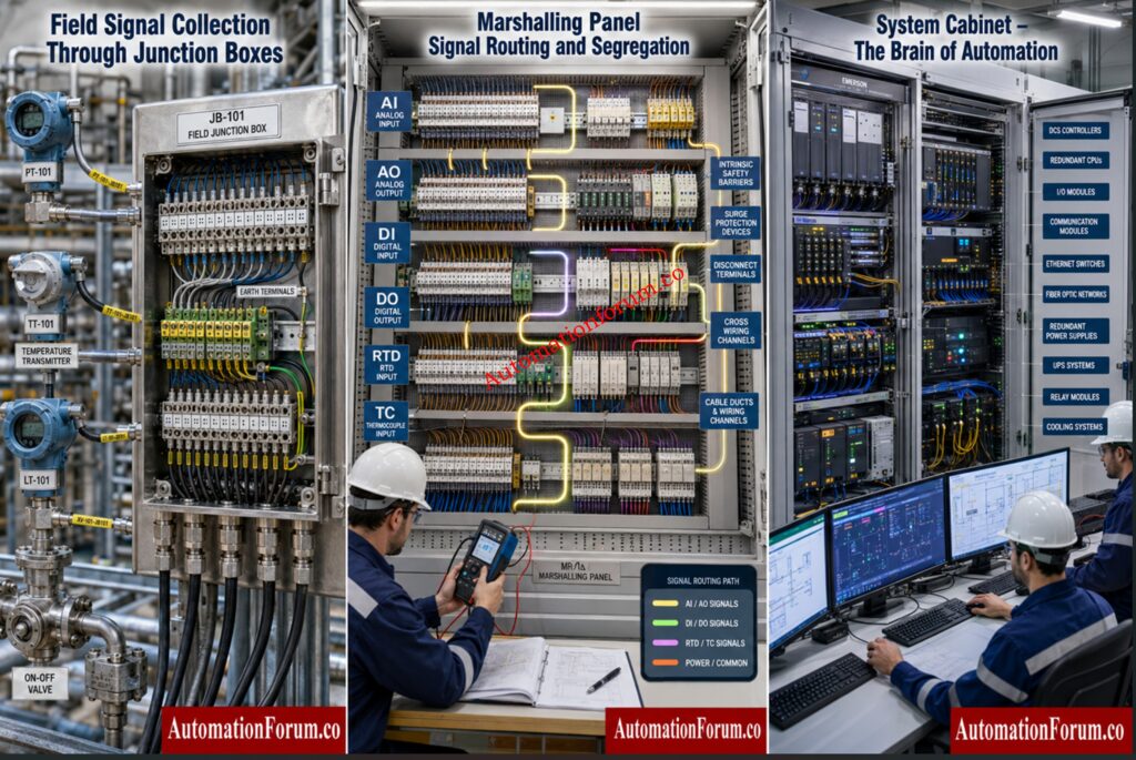
The System Cabinet is the enclosure containing active automation hardware. This is the brain of the automation system and deals with processing, communication, power distribution, diagnostics and integration.
A System Cabinet is a control enclosure that houses the hardware used to Signal Segregation in Marshalling Panels execute plant logic and manage communication between field signals and control software.
Why a System Cabinet Is Called the Brain of Automation
It is called the brain because it contains the controller hardware that makes decisions, executes control logic, and coordinates process actions.
The Engineering Secrets Behind Reliable System Grounding: Grounding and Bonding in Instrumentation and Control Systems
Internal Components of a System Cabinet
A System Cabinet may contain PLC CPUs, DCS controllers, I O modules, communication cards, Ethernet switches, redundancy modules, power supplies, relays, and network components.
System Cabinet Architecture in Process Plants
Depending on the project, the system cabinet may be arranged as a controller cabinet, I O cabinet, network cabinet, server cabinet, or engineering workstation cabinet.
Redundancy Architecture in System Cabinets
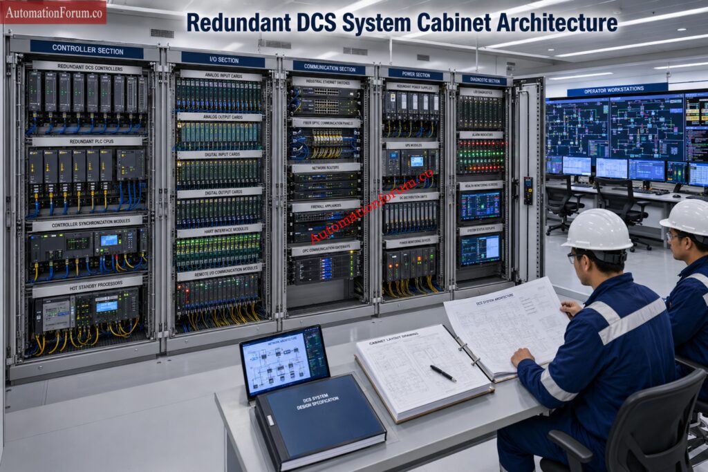
Critical plants often use redundant controllers, redundant communication paths, and redundant power supplies. This improves availability and reduces the impact of a single hardware failure.
Discover Essential DCS Testing Steps Before Acceptance: Factory Acceptance Test Procedure for Distributed Control System DCS
Advantages and Limitations of a System Cabinet
The system cabinet provides intelligence, control, diagnostics, and communication. It is indispensable in modern automation systems.
It requires careful environmental protection, proper cooling, clean installation, and disciplined maintenance. It also needs stronger documentation than passive enclosures.
Real Plant Example
In a DCS based plant, the system cabinet receives organized signals from marshalling, processes them through controllers, and then sends outputs to actuators, alarms, interlocks, trends, and operator graphics.
Critical Design Insights Every Automation Engineer Needs: Marshalling Cabinet drawing and its significance
How Signal Travels from Field Instrument to Operator Station
Traditional plants used large amounts of physical cross wiring and extensive marshalling. Conventional DCS design improved structure and traceability. Later, electronic marshalling reduced physical wiring by allowing flexible channel assignment. Smart I O and remote I O reduced the need for long field cable runs.
Modern digital architectures continue to simplify wiring and improve diagnostics. Even so, the essential logic remains the same. Field devices still need to be collected, organized, and delivered to the automation system in a controlled and traceable way.
Example
A pressure transmitter measures process pressure in the field. Its cable enters a nearby Junction Box. From there, a multicore cable carries the signal to the Marshalling Panel. The marshalling panel recognizes the signal and directs it to the appropriate outgoing terminal. The outgoing side is connected to the proper channel in the System Cabinet. The controller receives the value, applies control logic and communicates the result to the operator station.
This journey is important because every stage has a different purpose. If one stage is misunderstood, the whole loop becomes harder to install, test, and maintain.
Stop Missing These Essential Field Wiring Requirements: 25-Point Instrumentation Junction Box (JB) Wiring and Termination Checklist for EPC Engineers
Marshalling Panel vs Junction Box vs System Cabinet
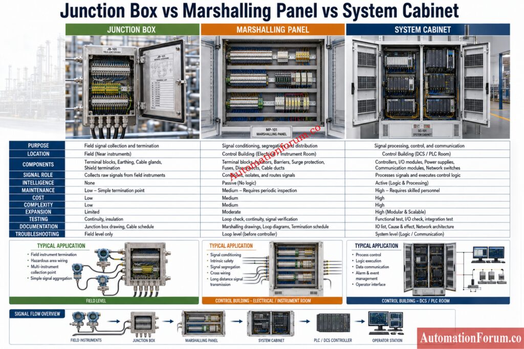
| Parameter | Junction Box | Marshalling Panel | System Cabinet |
| Purpose | Provides termination and protection for field wiring | Provides routing, organization, and signal distribution | Provides control, automation, and active processing |
| Location | Usually installed in the field near instruments | Usually installed in the control room or marshalling room | Usually installed in the control room or system room |
| Signal Role | Collects field signals from instruments | Arranges and redistributes signals | Processes signals and executes control logic |
| Intelligence | No intelligence | No control intelligence | Has active intelligence and control capability |
| Components | Passive termination hardware, cable glands, earthing terminals, shield termination points | Terminal hardware, protection devices, routing elements, labeling system | Controllers, cards, power supplies, communication hardware, network devices |
| Cross Wiring | Does not perform cross wiring | Performs cross wiring between field side and system side | Normally receives organized terminations rather than field cross wiring |
| Power Handling | Usually handles only local termination and small signal level connections | Handles signal level protection and segregation | Distributes and uses regulated control power for active equipment |
| Maintenance Focus | Supports field level maintenance | Supports signal tracing and loop troubleshooting | Supports automation hardware maintenance |
| Commissioning Effort | Basic checks such as continuity and termination verification | Detailed checks such as routing, tagging, and shield verification | Highly detailed checks such as logic, power, communication, and redundancy verification |
| Cost | Lowest cost | Moderate cost | Highest cost |
| Complexity | Simple and compact | Medium complexity | High complexity |
| Expansion | Expansion is local and limited by enclosure size | Expansion depends on spare terminals and panel space | Expansion depends on rack space, card capacity, and system design |
| Documentation | Cable schedule, terminal schedule, gland details | Cross wiring schedule, loop drawings, terminal plan | Rack drawings, card schedule, network drawings, system architecture |
| Testing | Checked for continuity, polarity, and termination quality | Checked for routing accuracy, segregation, and shield integrity | Checked for logic, power quality, communication, and system response |
| Troubleshooting | Helps isolate field cable issues | Helps isolate wiring and routing issues | Helps isolate controller, card, and hardware issues |
| Signal Types | May carry many field signal types | Separates analog signals, digital signals, RTD, thermocouple, and pulse signals | Receives system ready signal inputs and outputs for control action |
| Hazardous Area Suitability | Commonly used near field hazardous areas | Usually located in a safe area | Normally installed in a controlled and protected room |
| Labeling Need | Needs local identification only | Needs detailed loop labels and terminal labels | Needs card labels, channel labels, and rack labels |
| Noise Control | Limited noise control | Improves noise management through segregation and grounding | Depends on system design and enclosure discipline |
| Overall Role | Termination | Organization | Control |
| Typical Project Use | First point of field cable collection | Intermediate point for signal routing and redistribution | Final point for control hardware and automation execution |
Test Smarter and Eliminate Expensive Site Rework: Advanced 25-MCQ on Instrumentation Junction Box Schedule Engineering Drawing
How EPC Engineers Select the Right Enclosure
| Factor | Detailed Explanation | Practical Impact |
| Number of Signals | The number of loops is one of the first design drivers. More signals usually mean more cable entries, more terminals, and stronger marshalling requirements. | Helps determine the enclosure size, terminal count, and wiring layout. |
| Future Expansion | Projects should include spare terminal capacity and spare rack space wherever possible. Future modifications become much easier when space is reserved early. | Reduces rework and makes later plant changes easier. |
| Hazardous Area Classification | Enclosures and glands must match the site classification. It influences the choice of material, certification and installation procedure. | Ensures compliance with safety and suitable equipment choices. |
| Maintenance Philosophy | If the plant is going to require a lot of troubleshooting and changes, a more robust marshalling concept can decrease future effort. | Improves accessibility, traceability and serviceability. |
| Redundancy Requirements | Critical plants may require redundant controllers, redundant communication paths, and redundant power supplies in the system cabinet. | Improves reliability and reduces the effect of hardware failure. |
| Safety Requirements | Safety related signals must be clearly separated and accurately identified. Documentation must be robust Installation must be installed to acceptable standards. | Supports safe operation and compliance with regulations. |
| Project Budget | Budget influences the size, quality, and feature level of each enclosure. A low initial cost can lead to higher lifecycle cost if the design becomes hard to maintain. | Affects both short term procurement and long term plant performance. |
| Lifecycle Cost | The cheapest design is not always the most economical. A slightly better enclosure strategy can reduce downtime, rework, and maintenance time for years. | Lowers long term operating and maintenance cost. |
Master Signal Routing Techniques Used By EPC Experts: Instrument Junction Box (JB) schedule
Common Engineering Mistakes in Signal Routing Architecture
| Common Engineering Mistake | Detailed Explanation | Practical Impact |
| Using a Junction Box as a Substitute for Marshalling | A Junction Box only provides field termination and protection. It cannot perform full signal routing or cross wiring like a Marshalling Panel. | Confuses during loop inspections, signal tracing and maintenance. |
| Mixing Analog and Digital Signals Without Segregation | Separate analog and digital circuitry to minimize interference and enhance clarity. | May generate noise issues and complicate debugging. |
| Poor Shield Grounding Practice | Shields should be grounded in accordance with the grounding philosophy of the project. Poor handling can inject unnecessary noise into the loop. | Causes unreliable readings, signal interference and false warnings. |
| Missing Spare Terminals | Provide spare terminals for future alterations, modification, and maintenance flexibility. | Costly, slow, disruptive future expansion. |
| Incomplete Tagging | All wires, terminals and loops will be clearly identified. Tags not present reduces traceability. | Makes loop tracing slow, confusing, and error prone. |
| Wrong Intrinsic Safety Barrier Selection | IS barriers must match the signal type and hazardous area requirement. Incorrect selection can violate safety rules. | Can compromise safety and create compliance problems. |
| Inadequate Terminal Tightening | Loose terminals can cause intermittent contact, heat generation, and unstable signals. | May lead to frequent faults and unreliable operation. |
| Incorrect Loop Numbering | Loop numbers must match drawings, schedules, and field labels. Any mismatch creates confusion. | Makes commissioning slower and less efficient. |
| Poor Cable Gland Selection | Cable glands must suit the cable size, enclosure type, and protection requirement. Wrong glands reduce sealing quality. | Can allow moisture entry and damage internal components. |
| No Clear Cross Wiring Schedule | Cross wiring must be documented clearly so each field signal reaches the correct system channel. | Leads to misrouting and repeated rework. |
| No Allowance for Future Expansion | The panel should include spare capacity for additional loops and system changes. | Forces early modifications and increases project cost later. |
| Confusing Field Termination Drawings with System Drawings | Field drawings and system drawings serve different purposes and must not be mixed. | Makes installation, testing, and verification much harder. |
| Using the Wrong Terminal Type for Disconnect Needs | Disconnect terminals should be used where isolation and testing are required. Standard terminals may not be enough. | Makes testing and isolation difficult. |
| Overcrowding the Panel | Too many components in a small space reduce access and increase wiring difficulty. | Reduces maintenance access and raises the chance of errors. |
| Weak Revision Control | Drawings and schedules must be updated whenever changes are made. Poor revision control creates mismatch between documents and field work. | Causes divergence between installation records and actual wiring. |
Avoid Documentation Mistakes That Cause Major Delays: Instrument Index Generator for EPC Instrumentation Projects
FAQs on Marshalling Panel vs Junction Box vs System Cabinet
What is the difference between a Junction Box and a Marshalling Panel ?
A Junction Box is used to collect and terminate field wiring near the instruments. A Marshalling Panel is used to organize, route, and redistribute those signals toward the control system.
What does a Marshalling Panel do in instrumentation ?
A Marshalling Panel receives field cables and arranges them in a clear signal order. It makes loop tracing, cross wiring, and control system connection much easier.
What is the function of a System Cabinet ?
A System Cabinet houses active control hardware such as PLC or DCS components. It processes signals, runs control logic, and supports communication with the plant system.
Why is cross wiring used in marshalling ?
Cross wiring is used because field cable order usually does not match control system I O order. It helps route each signal to the correct controller channel.
Can a Junction Box contain active control hardware ?
No, a Junction Box is normally a passive enclosure for termination only. Active control hardware belongs in a System Cabinet or similar control enclosure.
What signals are normally routed through a Marshalling Panel ?
Marshalling Panels commonly route analog inputs, analog outputs, digital inputs, digital outputs, RTD, thermocouple, and pulse signals. The panel separates and organizes them before they reach the system cabinet.
SCADA Acceptance Testing Steps Every Engineer Should Know: Factory Acceptance Test (FAT) Activities for SCADA System: Step-by-Step Checklist
Why are System Cabinets used in DCS and PLC systems ?
System Cabinets hold the hardware that actually controls the process. They contain the CPU, I O modules, power supplies, and communication devices needed for automation.
How do EPC engineers decide between direct wiring and marshalling ?
They look at signal count, project size, future expansion, safety needs, and maintenance philosophy. Larger and more complex plants usually need marshalling for better traceability.
What is the role of shielding in these enclosures ?
Shielding helps reduce electrical noise and signal interference. Proper shield termination improves signal stability and prevents false readings.
What are the common mistakes in signal routing architecture ?
Common mistakes include poor labeling, wrong cross wiring, missing spare terminals, weak shield grounding, and mixing signal types without segregation. These errors increase commissioning time and make troubleshooting difficult.
Field Reading Problems Solved Using Proven Methods: Loop Checking Field vs Control Room Reading Mismatch Explained
Best Practices for Instrumentation Projects
- Define the signal architecture early in engineering.
- Keep field termination, marshalling, and control hardware responsibilities separate.
- Maintain strict loop numbering discipline.
- Use clear and durable labels.
- Reserve spare terminals and spare cabinet space.
- Keep analog, digital, and safety signals segregated.
- Apply the correct shield grounding philosophy.
- Select enclosure ratings according to site conditions.
- Standardize terminal block types across the project.
- Use approved cross wiring schedules.
- Verify drawings before cable installation.
- Keep revision control strict.
- Involve commissioning teams during design review.
- Plan maintenance access from the beginning.
- Document all deviations immediately.
- Verify intrinsic safety details carefully.
- Use consistent cable identification practices.
- Allow for future expansion.
- Protect active cabinet hardware from heat and dust.
- Train field and control teams on the same signal philosophy.
Avoid PLC Panel Failures With Proper FAT Planning: Factory Acceptance Test (FAT) of a PLC Panel: A Step-by-Step Basic Guide
Conclusion: Final Takeaway for EPC and Instrumentation Engineers
A Junction Box provides protection and termination. A Marshalling Panel provides signal organization and routing. A System Cabinet provides control and automation.
When these three elements are designed properly, the plant becomes easier to build, commission, operate, and maintain. For EPC projects, the value is not only in the hardware itself but in the quality of the signal architecture. Good design reduces confusion, improves reliability, and saves time throughout the asset life cycle.
A Junction Box terminates field wiring, a Marshalling Panel organizes and routes signals, and a System Cabinet contains active control hardware such as PLC or DCS components. Together they form the standard signal path from field instruments to the automation system in large industrial plants.
Refer the below link for the Site Acceptance Test (SAT) Procedure for PLC Systems