- What is Factory Acceptance Test in DCS Systems
- Objectives of DCS FAT in Process Industries
- Difference Between FAT and SAT in DCS Projects
- Documents Required Before DCS FAT
- DCS FAT Team Responsibilities
- DCS FAT Test Setup and Simulation Arrangement
- Step By Step DCS FAT Procedure for Distributed Control System DCS
- Overall System Configuration Verification
- Visual Inspection During DCS FAT
- Power Up Testing in DCS FAT
- Controller Testing in DCS FAT
- IO Loop Testing in DCS Factory Acceptance Test
- Cause and Effect Verification in DCS FAT
- DCS Graphics and Operator Station Testing
- Alarm and Event Testing in DCS
- Redundancy Testing in DCS FAT
- Communication Interface Testing in DCS
- Fail Safe Testing in DCS FAT
- Online Modification Testing in DCS
- System Diagnostic and Cybersecurity Testing in DCS
- Backup and Restore Testing in DCS FAT
- Common Problems Found During DCS FAT
- Wrong IO Mapping Problems
- Incorrect Scaling Issues
- Logic Mismatch and Shutdown Sequence Problems
- Duplicate IP Address and Communication Failure
- Redundancy Failure During Switchover Testing
- Alarm Flooding During Startup Simulation
- Graphics Mismatch and Operator Display Problems
- Wrong Fail Safe Action in DCS Systems
- Best Practices for Successful DCS FAT
- Lessons Learned From Real DCS Projects
- Why DCS FAT is Critical Before Site Commissioning
- Future Trends in DCS FAT
- DCS Factory Acceptance Test Checklist Excel
- Frequently Asked Questions About DCS FAT
- What is DCS FAT?
- Why is DCS FAT important?
- What is tested during DCS FAT?
- What is the difference between FAT and SAT?
- Why is redundancy testing important?
- What is cause and effect testing?
- What are common FAT failures?
- What is fail safe testing?
- Why is alarm testing important?
- What is online modification testing?
- What documents are required for FAT?
- Why are operators involved in FAT?
- What is communication interface testing?
- Why are backups tested during FAT?
- What is a punch point during FAT?
- Final Engineering Insight on DCS Factory Acceptance Testing
Factory Acceptance Test for a Distributed Control System is one of the most critical stages in any automation project. In oil and gas plants, refineries, power plants, LNG terminals, chemical units, pharmaceutical plants, fertilizer complexes, and steel industries, a poorly executed DCS FAT can create massive commissioning delays, shutdown risks, startup instability, and expensive rework.
Experienced commissioning engineers know one important reality. Problems discovered during FAT are manageable. Problems discovered during startup can become project disasters.
A DCS Factory Acceptance Test is not simply a checkbox activity performed before shipment. It is a systematic verification process where the complete control system is validated against approved engineering documents, process philosophy, shutdown logic, communication architecture, graphics, alarms, redundancy, and fail safe behavior.
The purpose is simple. Identify and eliminate problems before the system reaches the site.
Modern DCS systems contain thousands of IO signals, complex interlocks, communication gateways, redundant controllers, alarm systems, historians, engineering stations, operator consoles, cybersecurity layers, and third party package interfaces. Even a small mismatch in logic or scaling can create dangerous operating conditions during plant startup.
A properly executed DCS FAT improves startup reliability, reduces commissioning stress, improves operator confidence, and significantly lowers project risk. This is why experienced automation engineers never treat FAT as a paperwork exercise. They treat it as the last opportunity to verify the complete system before real process fluid enters the plant.
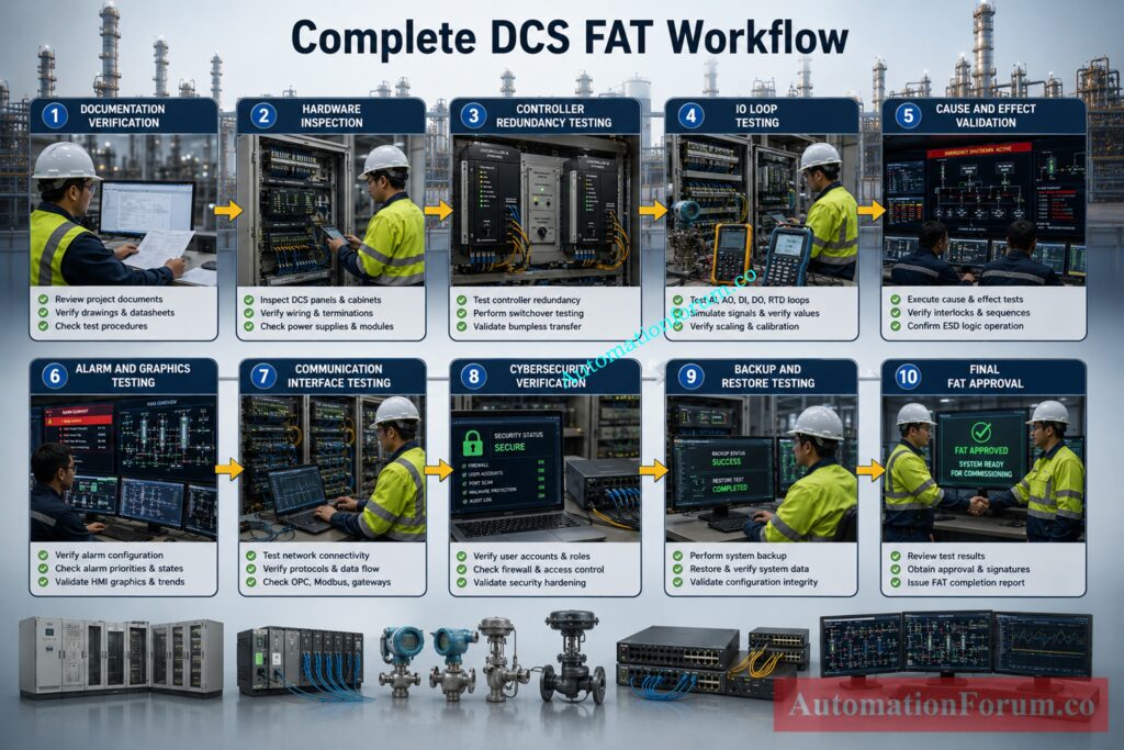
The uploaded reference document also emphasizes detailed FAT workflow structure, IO verification, redundancy testing, logic validation, online modification testing, and diagnostic verification for DCS systems.
Stop Choosing the Wrong PLC or DCS System: PLC vs DCS – Which One Should you Choose for your Automation System?
What is Factory Acceptance Test in DCS Systems
Purpose of DCS Factory Acceptance TestingFactory Acceptance Test in a DCS project is a structured verification process performed at the vendor facility before shipment of the Distributed Control System to the plant site.
Purpose of DCS Factory Acceptance Testing
The FAT confirms that:
- Hardware is correctly assembled
- Software configuration matches approved documents
- Control logic functions correctly
- Alarms and graphics operate properly
- Communication interfaces are stable
- Redundancy operates seamlessly
- Fail safe actions are correct
- Operator stations function properly
- Diagnostics and backups work correctly
The FAT normally occurs near the end of the engineering phase before shipment to site.
DCS FAT Lifecycle in Process Industries
A typical DCS FAT lifecycle includes:
- Internal vendor FAT
- Pre FAT corrections
- Customer witnessed FAT
- Punch point closure
- Final approval
- Shipment release
Internal FAT vs Customer Witnessed FAT
Internal FAT is usually conducted by the DCS vendor before inviting the customer. Customer FAT is the formal witnessed test involving client representatives, EPC teams, operations personnel, and commissioning engineers.
The FAT approval philosophy is important. Every deviation discovered during testing must be recorded as a punch point with status tracking and closure responsibility.
Objectives of DCS FAT in Process Industries
The main objectives of DCS FAT include:
- Hardware verification
- Software verification
- Controller redundancy testing
- Network redundancy validation
- Communication verification
- IO mapping validation
- Cause and effect testing
- Alarm verification
- Graphics validation
- Historical trending verification
- Fail safe behavior confirmation
- Operator functionality testing
- Cybersecurity readiness checks
- Backup and restore validation
- Documentation verification
The ultimate objective is to ensure that the DCS arriving at site behaves exactly as intended during plant operation.
Refer the below links for the Understanding the Difference Between DCS Components: ES, OS, and AS
Difference Between FAT and SAT in DCS Projects
| Parameter | FAT | SAT |
| Test location | Vendor facility | Plant site |
| Main objective | Verify manufacturing and configuration | Verify installation and integration |
| Process availability | Simulated process only | Actual plant environment |
| Signal testing | Simulated IO signals | Real field signals |
| Hardware readiness | Factory assembled system | Installed field system |
| Team participation | Vendor and client representatives | Site commissioning teams |
| Communication verification | Limited integration simulation | Full plant integration |
| Typical problems discovered | Logic errors, scaling issues, graphics mismatch | Wiring errors, grounding issues, communication failures |
| Shutdown testing | Simulated shutdown logic | Real integrated shutdown testing |
| Documentation focus | FAT protocols and test sheets | Site commissioning reports |
| Environment | Controlled factory environment | Real operating environment |
| Final goal | Shipment approval | Plant startup readiness |
Avoid Costly DCS HART Configuration Mistakes Today: Best Practices for Configuring HART Parameters in DCS Software
Documents Required Before DCS FAT
A successful DCS FAT depends heavily on documentation quality. Incomplete documentation is one of the biggest reasons for FAT delays.
Required documents include:
- Functional Design Specification
- Cause and Effect Matrix
- Control philosophy
- Instrument index
- IO database
- Alarm list
- Graphics list
- Loop diagrams
- System configuration drawings
- Cabinet GA drawings
- Communication architecture
- Network topology
- Approved FAT procedure
- Test sheets
- Software backups
- Shutdown narratives
- Sequence logic documents
Experienced FAT engineers always insist on document freezing before FAT begins. Last minute logic changes during FAT often create confusion, repeated testing, and documentation mismatch.
DCS FAT Team Responsibilities
Role of Client Representatives During FAT
- Witness testing
- Verify compliance with specifications
- Approve punch point closure
- Validate operational philosophy
Role of DCS Vendor During Factory Acceptance Testing
- Arrange FAT setup
- Execute testing
- Demonstrate functionality
- Resolve technical issues
Role of System Integrator in DCS FAT
- Verify software integration
- Validate communication interfaces
- Support troubleshooting
Role of Instrumentation and Process Engineers
- Validate IO database
- Verify instrument ranges
- Confirm alarm settings
- Validate process sequences
- Verify interlocks
- Confirm shutdown logic
Role of Commissioning and Operations Teams
- Validate graphics usability
- Verify alarm philosophy
- Assess operator friendliness
- Verify startup readiness
- Validate fail safe behavior
- Review sequence logic
Only Experts Can Pass This DCS Cascade Quiz: DCS Cascade Control Loop Instrumentation Quiz – 25 Expert-Level Questions
DCS FAT Test Setup and Simulation Arrangement
A complete DCS FAT setup normally includes:
- Engineering workstation
- Operator workstations
- Application servers
- Historians
- Redundant controllers
- Redundant network switches
- Communication gateways
- Marshalling cabinets
- System cabinets
- Printers
- Alarm annunciators
- Simulation panels
- Signal generators
- Loop simulators
- UPS systems
Importance of Realistic FAT Environment Simulation
Real DCS to MCC Logic Questions That Challenge Engineers: Test Your Knowledge: Instrument Logic Diagram Quiz Based on Real DCS to MCC Logic
Step By Step DCS FAT Procedure for Distributed Control System DCS
Overall System Configuration Verification
Typical checks include:
Cabinet Quantity and Hardware Verification
Wrong or missing labelled cabinets can cause serious misunderstanding during site installation and commissioning procedures.
Controller and Workstation Verification
All process controllers, redundancy controllers, safety controllers and communication processors are verified against the approved Bill of Materials and system architectural drawings.
The engineering team confirms:
- Correct controller model
- Correct firmware version
- Proper slot allocation
- Redundant controller pairing
- Correct module arrangement
Already one bad controller module can damage several process regions during commissioning.
The FAT team checks all engineering stations, operator stations, history servers, application servers, alarm servers and maintenance stations.
Each workstation is checked for:
- Correct hostname
- Correct IP address
- Operating system readiness
- DCS software installation
- Network connectivity
- Time synchronization
Network Topology and Communication Verification
The complete DCS network architecture is verified carefully because communication problems are among the most common FAT issues found during integrated testing.
Typical verification includes:
- Redundant network configuration
- Fiber optic communication paths
- Switch configuration
- VLAN configuration
- Ring redundancy
- Firewall segregation
- Third party communication paths
Network drawings should exactly match the actual installed configuration.
All communication interfaces are checked including:
- Modbus TCP modules
- Modbus RTU interfaces
- OPC servers
- Ethernet gateways
- Profibus interfaces
- Foundation Fieldbus interfaces
- Serial communication modules
Improper communication module allocation often leads to integration failures during site commissioning.
Learn to Read DCS Cascade Loops Professionally: How to Read a DCS Cascade Control Loop Diagram: A Complete Guide with Example
Hardware BOM and Power Distribution Verification
The FAT team verifies installed hardware against approved BOM.
Verification includes:
- Controller modules
- Power supplies
- Communication cards
- Terminal blocks
- Relays
- Switches
- Network components
- Workstation hardware
This step helps identify missing hardware before shipment.
Power distribution checks confirm proper arrangement of:
- AC distribution
- DC distribution
- UPS supply
- Redundant power feeds
- Circuit breakers
- Fuse ratings
- Power isolation
It is also important to check the separation of power between critical and less critical systems.
This stage ensures that the delivered DCS system matches approved engineering drawings, network architecture, and project specifications before detailed testing begins.
Critical DCS Cybersecurity Risks Every Plant Must Prevent: DCS Cybersecurity: Mitigating Risks in Industrial Automation
Visual Inspection During DCS FAT
Visual inspection is one of the simplest FAT activities but often identifies serious workmanship problems that could later create reliability issues in the field.
Experienced commissioning engineers always spend significant time during this stage because poor panel workmanship usually indicates weak fabrication quality.
Typical inspection activities include:
Cabinet Inspection and Physical Verification
The FAT team checks the physical condition of all cabinets for:
- Mechanical damage
- Paint quality
- Door alignment
- Lock operation
- Cabinet cleanliness
- Proper ventilation
- Structural integrity
Transport damage or fabrication defects identified during FAT should be corrected before shipment.
Cable Dressing and Wiring Quality Inspection
Cable routing inside the cabinet should be neat, organized, and properly segregated.
Engineers verify:
- Signal cable separation
- Power cable segregation
- Proper cable tie spacing
- Proper routing paths
- No cable stress
- No sharp bending
Poor cable dressings can lead to further maintenance difficulties and can cause electrical noise problems.
Control Valve DCS Loop Problems? Use This Checklist: Checklist for Troubleshooting Control Valve in DCS Loop
Tag Checking and Label Verification
Verification includes:
- Terminal numbers
- Cable numbers
- Module labels
- Junction identification
Cabinet labels and nameplates should clearly identify:
- Cabinet number
- Voltage level
- Panel function
- Warning notices
- Safety instructions
Incorrect labeling creates operational confusion during startup activities.
Earthing and Grounding Inspection
Proper earthing is critical for stable DCS operation.
Checks include:
- Signal grounding
- Protective grounding
- Earth continuity
- Shield termination
- Ground bus arrangement
Improper grounding is a major cause of communication instability and signal noise.
Avoid DCS Integration Failures with This Proven Guide: Integrating Third-Party Systems with a Distributed Control System (DCS): Checklist
Cooling Fan and Terminal Tightness Inspection
Cooling fans and cabinet ventilation systems are inspected for:
- Proper installation
- Airflow direction
- Fan operation
- Filter cleanliness
Overheating can reduce controller reliability and shorten equipment life.
Loose terminals are among the most common commissioning issues found at site.
Engineers verify:
- Terminal tightness
- Proper ferrule crimping
- No exposed conductors
- Correct wire insertion
Wiring Quality Inspection
Panel wiring should comply with project standards and vendor practices.
Checks include:
- Proper wire color coding
- Correct ferrule usage
- Proper gland installation
- No damaged insulation
- Clean routing
Ferrule Verification
Wire ferrules should match approved numbering schemes and be properly crimped.
Loose or incorrect ferrules frequently create intermittent signal problems during plant startup.
Poor cable dressing and weak panel workmanship observed during FAT usually indicate weak fabrication quality control and should never be ignored.
Reduce Alarm Flooding with This DCS Checklist: DCS Alarm Management Checklist
Power Up Testing in DCS FAT
Power up testing validates stable startup of the complete DCS system under normal operating conditions.
This stage confirms that all system components can energize correctly without abnormal alarms, overheating, or communication failures.
Typical checks include:
Sequential Power Application Procedure
Power should be applied in a controlled sequence according to vendor recommendations.
Typical sequence includes:
- UPS energization
- DC power supply startup
- Network switch energization
- Controller startup
- Server startup
- Workstation startup
Incorrect startup sequence may create communication failures or controller synchronization problems.
UPS Power Supply Verification
UPS systems are verified for:
- Input voltage
- Output voltage
- Battery health
- Alarm operation
- Backup duration
Critical DCS systems should continue operating during temporary power disturbances.
Voltage Monitoring Verification
Engineers monitor:
- AC voltage stability
- DC voltage stability
- Ripple voltage
- Power supply loading
Abnormal voltage fluctuation may indicate wiring problems or overloaded power supplies.
Think You Know DCS? Prove It Here: Quiz on Distributed Control Systems(DCS)
Redundant Power Supply Operation Verification
Redundant power supplies are tested by removing one supply at a time while monitoring controller operation.
A healthy redundant system should continue operating without interruption.
System Boot Sequence Verification
The complete startup sequence is monitored carefully.
Checks include:
- Controller initialization
- Server startup
- Database loading
- Communication startup
- Alarm server initialization
- Historian startup
Unexpected boot errors should be investigated immediately.
Controller Startup Validation
Controllers are checked for:
- Healthy startup diagnostics
- Module recognition
- Communication status
- Synchronization
- CPU health
Server Startup Validation
Application servers and historians are verified for:
- Database integrity
- Alarm services
- Historical data services
- Communication services
- User login functionality
Operator Workstation Health Verification
Operator and engineering stations are checked for:
- Graphics loading
- Faceplate operation
- Alarm display
- Trend functionality
- Network communication
Before power is applied to the DCS system, engineers must ensure that there are no short circuits, grounding difficulties, or erroneous voltage connections, because power failures can destroy expensive control-system hardware.
SCADA and DCS Network Design Rules Engineers Ignore: Network Switches requirements in “SCADA” and “DCS” Architecture
Controller Testing in DCS FAT
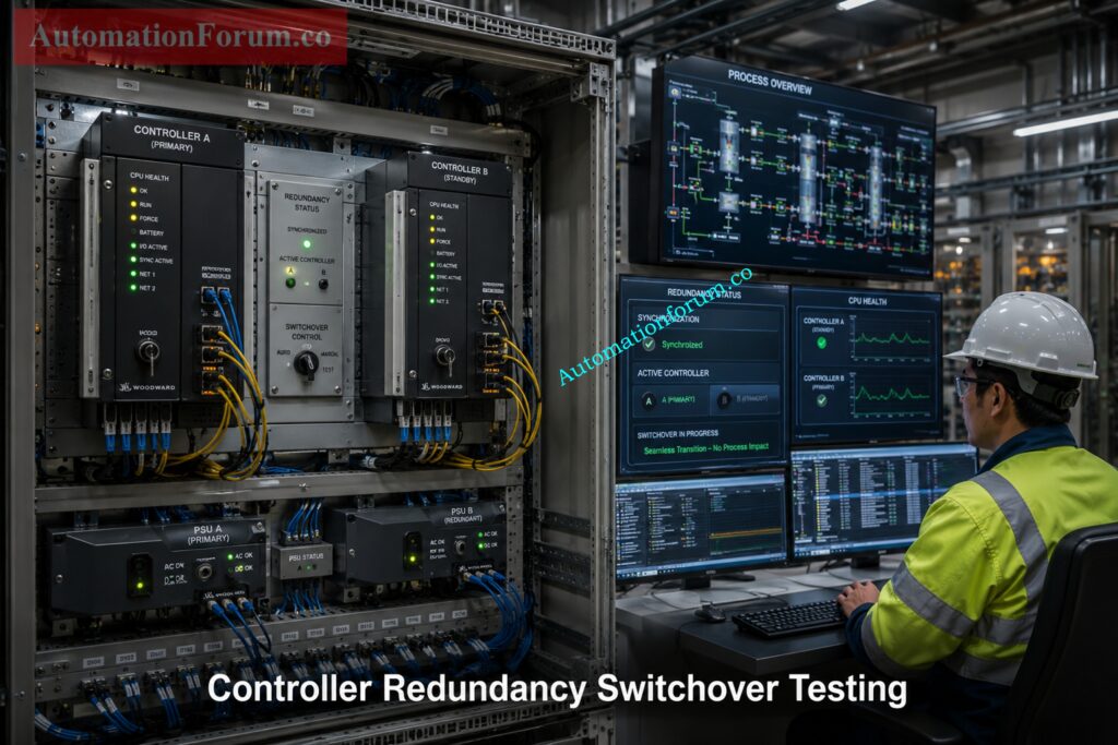
Controller testing evaluates controller stability, performance, and redundancy operation during Factory Acceptance Test. The purpose is to verify that the Distributed Control System performs reliably in normal and abnormal operation situations.
Typical tests of controllers include CPU health verification, redundancy switchover testing, controller synchronization checks, CPU loading verification, scan time verification and diagnostic monitoring.
Testing of the redundancy switchover is one of the most crucial FAT activities. In this test the main controller is switched to the standby controller to ensure that running control loops remain undisturbed. Successful switchover testing confirms the reliability of the controller redundancy system.
Common Controller Testing Activities
- CPU health verification
- Redundancy switchover testing
- Controller synchronization verification
- CPU loading verification
- Scan time verification
- Diagnostic monitoring
PLC and DCS Wiring Methods Every Engineer Should Know: Various types of Wirings in PLC & DCS Systems
IO Loop Testing in DCS Factory Acceptance Test
IO loop testing is one of the most important and time consuming FAT activities because it verifies correct signal processing between field instruments and the DCS.
Typical IO types tested during FAT include analog inputs, analog outputs, digital inputs, digital outputs, RTD inputs, thermocouple inputs, and pulse inputs.
Calibrated signal generators imitate analog signals to check that the DCS properly scales and converts the signals to engineering units.
Typical IO Types Tested During FAT
- Analog inputsIO Loop Testing in DCS Factory Acceptance Test
- Analog outputs
- Digital inputs
- Digital outputs
- RTD inputs
- Thermocouple inputs
- Pulse inputs
Common Analog Signal Verification Checks
- Scaling verification
- Engineering unit verification
- Alarm setpoint verification
- Trending verification
- Faceplate indication verification
- Historical recording verification
Common Digital Signal Verification Checks
- Status indication verification
- Alarm generation testing
- Command operation verification
- Sequence interaction testing
The reference FAT document also highlights detailed loop testing methods such as graphics indication verification, alarm validation testing, scaling checks, and controller response testing.
How APC Improves DCS Performance in Modern Plants: Advanced Process Control (APC): Working Principle, Components, Benefits, Applications and DCS Integration
Cause and Effect Verification in DCS FAT
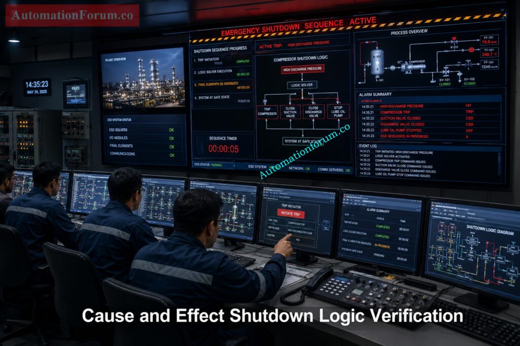
Cause and effect testing is used to verify the shutdown logic, interlocks, permissive functions and emergency shutdown sequences in the DCS.
This is one of the more crucial operations of the FAT as the wrong shutdown logic could damage equipment and create an unsafe operating condition.
Typical Cause and Effect Tests
- Shutdown logic testing
- Permissive verification
- Trip logic validation
- Sequence testing
- ESD verification
- Bypass testing
If, for example, temperature of compressor bearing is above the shutdown limit, the DCS must trigger the alarm, start the shutdown timer, give the trip command, show the shutdown feedback and document the sequence in the event log.
The purpose of this testing is to verify proper protective response by the DCS during off-normal plant conditions.
Alarm Priority and Trip Point Mistakes Explained Clearly: What are alarm, trip point, and alarm priority in DCS & PLC?
DCS Graphics and Operator Station Testing
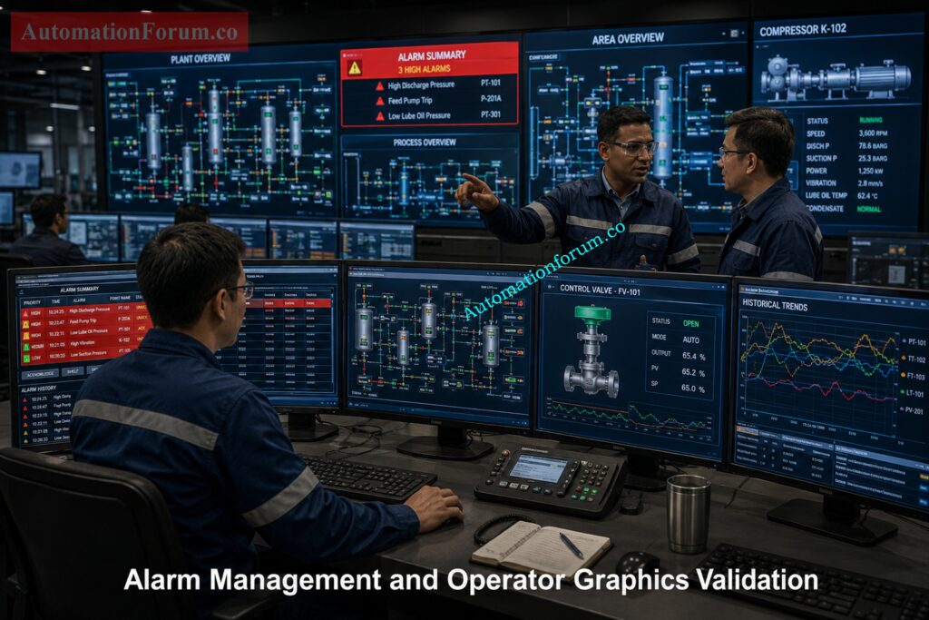
Operator graphics and HMI displays are extensively evaluated during FAT to ensure accurate process visualization and dependable operator engagement.
Common DCS Graphics Verification Checks
- Mimic display accuracy
- Dynamic object behavior
- Faceplate operation
- Trend displays
- Historical trending
- Color consistency
Operator graphics and HMI displays are extensively evaluated during FAT to ensure accurate process visualization and dependable operator engagement.
Marshalling Cabinet FAT Checks You Should Never Skip: Factory Acceptance Test (FAT) Procedure & Checklist for Marshalling Cabinets
Alarm and Event Testing in DCS
Graphics testing should involve operators, because poor HMI design can cause significant operational problems during startup and plant operation.
Typical Alarm Testing Activities
- Alarm priority verification
- Alarm acknowledgment testing
- Alarm shelving verification
- Event logging verification
- Time synchronization testing
- Alarm flood simulation
Poor alarm philosophy can lead to operator overload at starting and emergency scenarios, compromising operational safety and response efficiency.
DP Transmitter FAT Procedure Every Technician Must Follow: Factory Acceptance Test(FAT) Procedure for Differential Pressure(DP) Transmitter
Redundancy Testing in DCS FAT
Redundancy testing verifies uninterrupted DCS operation during hardware failures, communication failures, and power interruptions.
Typical Redundancy Tests
- Controller redundancy testing
- Network redundancy testing
- Server redundancy testing
- Power supply redundancy testing
- Communication redundancy testing
Live switchover testing is extremely important because configured redundancy alone does not guarantee seamless operation under real plant conditions.
MOV FAT Testing Steps That Prevent Startup Problems: Motor-Operated Valve (MOV) Factory Acceptance Test (FAT) Procedure
Communication Interface Testing in DCS
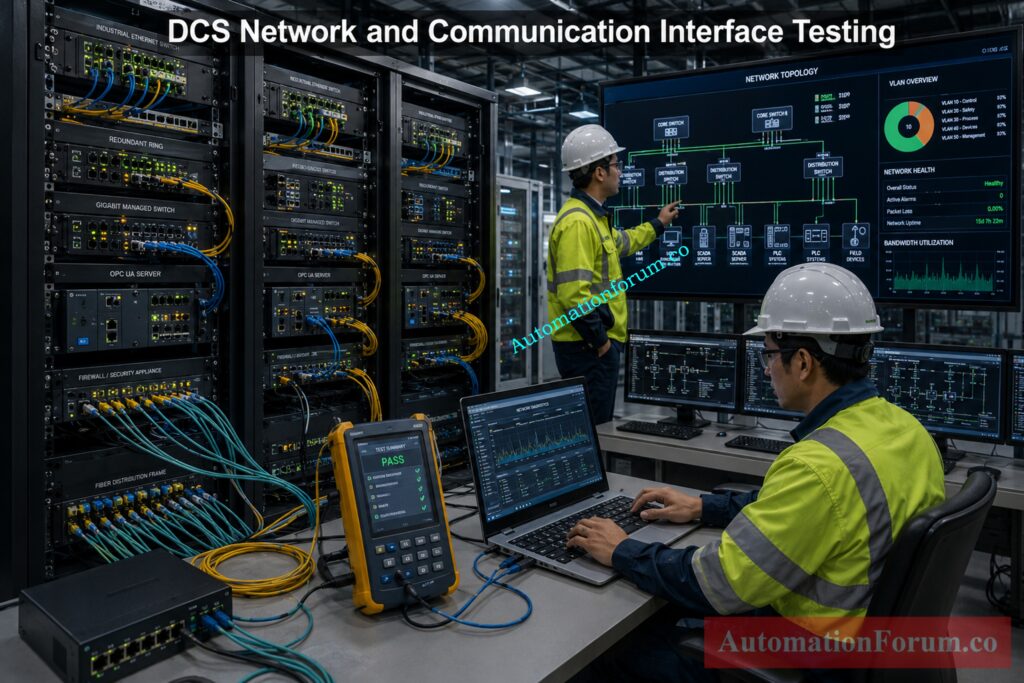
Modern DCS systems communicate with multiple third party systems and industrial communication networks. FAT verifies stable and reliable communication between all connected systems.
Common Communication Protocols Tested
- Modbus TCP
- Modbus RTU
- OPC communication
- HART communication
- Profibus
- Foundation Fieldbus
- Ethernet communication
Common Communication Problems Found During FAT
- Wrong register mapping
- Timeout issues
- Duplicate IP addresses
- Communication instability
- Incorrect byte order
SCADA FAT Activities Every Automation Engineer Must Verify: Factory Acceptance Test (FAT) Activities for SCADA System: Step-by-Step Checklist
Fail Safe Testing in DCS FAT
Fail safe testing is to verify the process is safe under abnormal operating conditions such as signal failure, controller problem or power loss.Diagnostic testing verifies the self monitoring capability of the DCS and ensures system faults are properly detected and reported.
Typical Fail Safe Verification Checks
- Analog fail safe response
- Digital fail safe action
- Communication loss behavior
- Sensor failure simulation
- Controller failure response
- Power loss response
For example, if a transmitter signal fails low, the DCS should automatically trigger the predefined fail safe action according to the approved process safety philosophy.
Control Valve FAT Mistakes That Cause Major Delays: Factory Acceptance Test (FAT) Procedure for Control Valve
Online Modification Testing in DCS
Modern DCS systems support online engineering modifications without interrupting plant operation. FAT verifies that these changes can be implemented safely and reliably.
Typical Online Modification Tests
- Online logic modification
- Online graphic modification
- Database changes
- Runtime downloads
- Controller update verification
This testing ensures engineering updates can be performed during plant operation without causing process interruptions.
PLC Panel FAT Checks Before Final System Approval: Factory Acceptance Test (FAT) of a PLC Panel: A Step-by-Step Basic Guide
System Diagnostic and Cybersecurity Testing in DCS

Diagnostic testing confirms the DCS self monitoring ability and ensures that system defects are correctly identified and reported.
Typical System Diagnostic Checks
- CPU diagnostics
- Module diagnostics
- Communication diagnostics
- Hardware failure simulation
- Event log verification
- System alarm generation
In current industrial automation systems, cybersecurity verification has also become one of the primary
Common Cybersecurity Verification Checks
- User access level verification
- Password policy validation
- USB restriction testing
- Antivirus verification
- Patch management checks
- Network segregation verification
Backup and Restore Testing in DCS FAT
Backup and restore verification is critical during FAT to verify sufficient disaster recovery capability prior to commissioning.
Typical Backup and Restore Verification Checks
- Controller backup verification
- Server backup verification
- Historian backup verification
- Database restoration testing
- Disaster recovery validation
Testing the backup properly reduces risks in commissioning and lowers downtime if there is a system failure in the future.
Common Problems Found During DCS FAT
Commissioning engineers that have done this many times run into the same problems during DCS Factory Acceptance Testing. If these flaws are not recognized during FAT they might cause significant start-up delays and operating risks during commissioning.
Wrong IO Mapping Problems
Typical examples include:
- Pressure transmitter connected to wrong tag
- Motor start command operating another motor
- Valve feedback assigned to incorrect equipment
These problems are frequently the result of database failures, marshalling bugs, or wiring incompatibility. Wrong IO mapping can generate unsafe operating conditions during startup because operators may accidentally operate the wrong equipment.
Incorrect Scaling Issues
Incorrect scaling is commonly identified during analog loop testing.
Typical examples include:
- Tank level showing 100 percent while actual level is 10 percent
- Pressure indication displaying wrong engineering units
- Flow transmitter showing unrealistic values
Scaling difficulties are typically caused by inappropriate low and high range configuration or errors in database import. Incorrect scaling might result in false alarms and unsteady control loop performance.
Logic Mismatch and Shutdown Sequence Problems
Logic mismatch occurs when implemented shutdown or interlock logic does not match the approved Cause and Effect Matrix.
Typical issues include:
- Incorrect shutdown sequence
- Missing permissive conditions
- Wrong timer values
- Incorrect interlock logic
A little logic error can lead to major operational issues during plant startup. Simulation of FAT logic can help to uncover these issues before commissioning.
Duplicate IP Address and Communication Failure
Duplicate IP addressing generates instability in communication throughout the DCS network.
Typical symptoms are:
- Communication interruption
- Random workstation disconnection
- OPC communication failure
- Slow graphics response
These issues are generally caused by poor network configuration or workstation cloning failures. For stable DCS communication, proper IP management is a must.
Redundancy Failure During Switchover Testing
Redundancy failures are often discovered during controller or network switchover testing.
Typical problems include:
- Controllers failing to synchronize
- Communication interruption during switchover
- Standby controller not taking over properly
- Redundant server mismatch
Many systems appear healthy until live failover testing begins. This is why repeated redundancy testing is mandatory during FAT.
Alarm Flooding During Startup Simulation
Alarm flooding occurs when hundreds of alarms appear during startup simulation or abnormal condition testing.
Common causes include:
- Poor alarm rationalization
- Incorrect alarm priority settings
- Communication alarm repetition
- Missing alarm suppression logic
Alarm flooding makes it difficult for operators to identify truly critical alarms during upset conditions.
Graphics Mismatch and Operator Display Problems
Graphics mismatch problems are common during operator station testing.
Typical examples include:
- Wrong equipment tag names
- Incorrect valve animation
- Wrong motor indication
- Missing process values
These issues usually occur because graphics were developed using outdated P&ID revisions or incorrect database links.
Wrong Fail Safe Action in DCS Systems
Wrong fail safe action is one of the most dangerous problems identified during FAT.
Typical examples include:
- Control valve failing open instead of fail close
- Shutdown valve remaining open during trip
- Incorrect response during communication failure
These problems are usually caused by incorrect actuator configuration or logic errors. Fail safe simulation testing is therefore critical during DCS FAT activities.
Best Practices for Successful DCS FAT
Experienced automation engineers follow several important practices to ensure smooth and effective DCS FAT execution. Proper planning and disciplined testing help reduce commissioning delays and startup risks.
Importance of Internal Pre FAT
Vendor internal FAT should eliminate major issues before customer FAT begins.
This helps identify:
- Logic errors
- Communication problems
- Graphics mismatch
- Database issues
A proper pre FAT reduces customer punch points and saves project time.
Testing Abnormal and Failure Conditions
Testing only normal operation is not enough.
The FAT team should also simulate:
- Power failure
- Communication loss
- Transmitter failure
- Controller switchover
- Emergency shutdown conditions
Shutdown Logic Verification Best Practices
Every shutdown and interlock sequence should be tested carefully.
Verification should include:
- Trip initiation
- Alarm generation
- Timer operation
- Reset functionality
- Shutdown sequence confirmation
Incorrect shutdown logic can create major operational risks during startup.
Importance of Proper Punch List Management
All FAT issues should be documented in structured punch lists.
Each punch point should include:
- Problem description
- Responsible person
- Completion status
- Retest requirement
Good punch tracking prevents unresolved issues from reaching the site.
Daily FAT Meetings and Coordination Practices
Daily FAT meetings improve coordination between:
- Client representatives
- DCS vendor
- Instrument engineers
- Commissioning teams
These meetings help review progress, resolve technical issues, and track pending punch points.
Backup Management and Documentation Control
Software backups should be updated continuously during FAT.
Regular backups should include:
- Controller configuration
- Graphics database
- Historian data
- Alarm configuration
Proper backup discipline helps recover quickly from configuration loss.
Importance of Updated Red Line Markups
Updated markups and red line drawings should always be maintained during FAT.
Important documents include:
- IO database
- Logic diagrams
- Cause and Effect Matrix
- Graphics markups
Using outdated drawings can create configuration mismatch during commissioning.
Lessons Learned From Real DCS Projects
Compressor Trip Logic Failure During FAT
During one refinery FAT, engineers discovered compressor shutdown logic failed because of incorrect permissive configuration. The issue would have caused major startup delays if discovered at site.
Wrong Analog Scaling Case Study
A tank level transmitter was incorrectly scaled from 0 to 10 meters instead of 0 to 20 meters. The operator display falsely indicated high level alarms.
Redundant Controller Synchronization Failure
Controller switchover testing revealed synchronization loss between primary and secondary controllers.
Modbus Communication Instability Example
A package unit repeatedly lost communication because of incorrect timeout settings.
Alarm Flood During Startup Simulation
Startup simulation generated over 800 alarms in two minutes because alarm priorities were poorly configured.
These are the kinds of problems FAT is designed to discover before shipment.
Why DCS FAT is Critical Before Site Commissioning
A properly executed FAT provides major benefits:
- Reduced startup delays
- Reduced commissioning rework
- Faster loop checking
- Improved operator confidence
- Safer plant startup
- Reduced shutdown risks
- Better project quality
- Reduced troubleshooting time
Experienced startup engineers know that every hour spent during FAT can save several days during commissioning.
Future Trends in DCS FAT
Modern FAT practices are evolving rapidly.
Future trends include:
- Remote FAT
- Virtual FAT
- Cloud based FAT
- Digital twin simulation
- AI assisted diagnostics
- Cybersecurity integrated FAT
- Simulation based commissioning
Advanced simulation platforms now allow realistic startup testing before physical plant readiness.
Refer the below link for Control Valve Site Acceptance Test (SAT) Procedure – Step-by-Step Field Guide
DCS Factory Acceptance Test Checklist Excel
Factory Acceptance Testing is one of the most critical phases in any Distributed Control System project. A properly executed DCS FAT helps identify logic issues, IO mapping errors, communication failures, alarm problems, redundancy issues, and fail safe mismatches before the system reaches the plant site.
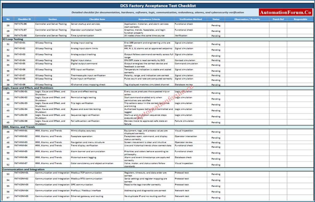
This professionally designed Excel checklist helps instrumentation, automation, commissioning, and control system engineers perform structured FAT activities in a systematic and traceable manner.
The workbook includes:
- Detailed DCS FAT checklist sections
- Documentation verification checklist
- Hardware and cabinet inspection checklist
- Controller and redundancy testing
- IO loop testing activities
- Cause and effect verification
- Alarm and graphics validation
- Communication interface testing
- Cybersecurity and backup verification
- Status dropdown tracking
- Pass Fail Pending color indication
- FAT summary dashboard
- Printable professional layout
Frequently Asked Questions About DCS FAT
What is DCS FAT?
DCS FAT is a factory level testing process performed before shipment of the Distributed Control System.
It verifies hardware, software, communication, logic, and system functionality before site commissioning.
Why is DCS FAT important?
DCS FAT helps identify problems before the system reaches the plant site.
It reduces startup delays, commissioning risks, and expensive rework activities.
What is tested during DCS FAT?
DCS FAT includes testing of hardware, software, alarms, graphics, communication, and redundancy systems.
Fail safe actions, shutdown logic, and operator functions are also verified.
What is the difference between FAT and SAT?
FAT is performed at the vendor facility before shipment of the DCS system.
SAT is performed at the plant site after installation and field integration.
Why is redundancy testing important?
Redundancy testing ensures continuous operation during controller, server, or network failure.
It confirms seamless switchover without disturbing plant operation.
What is cause and effect testing?
Cause and effect testing verifies shutdown logic and process interlock sequences.
It ensures the DCS responds correctly during abnormal process conditions.
What are common FAT failures?
Common FAT failures include wrong IO mapping, incorrect scaling, logic mismatch, and communication problems.
Redundancy failure and alarm flooding are also frequently identified.
What is fail safe testing?
Fail safe testing verifies safe system response during power loss or signal failure conditions.
It ensures valves, motors, and shutdown systems move to the correct safe state.
Why is alarm testing important?
Alarm testing verifies alarm priorities, acknowledgment, and event logging functionality.
Proper alarm testing prevents operator confusion during startup and upset conditions.
What is online modification testing?
Online modification testing verifies runtime changes without stopping the DCS process operation.
It confirms logic and graphics can be modified safely during operation.
What documents are required for FAT?
Important FAT documents include FDS, IO database, cause and effect matrix, and loop diagrams.
Graphics list, network architecture, and alarm configuration documents are also required.
Why are operators involved in FAT?
What is communication interface testing?
Communication interface testing verifies data exchange with third party systems and package units.
protocols like Modbus, OPC, Profibus, and Ethernet are commonly tested.
Why are backups tested during FAT?
Backup testing ensures the DCS system can recover after software corruption or hardware failure.
It validates controller, server, and historian restoration capability.
What is a punch point during FAT?
A punch point is a documented issue identified during FAT requiring correction before approval.
All punch points are tracked until proper closure and retesting are completed.
Final Engineering Insight on DCS Factory Acceptance Testing
Factory Acceptance Test is the backbone of successful DCS commissioning.
A properly executed FAT validates hardware integrity, software functionality, redundancy performance, communication stability, alarm philosophy, graphics behavior, and fail safe actions before the system reaches the plant.
Experienced engineers understand that startup success is heavily influenced by FAT quality. Thorough testing, disciplined documentation, realistic simulation, and strong teamwork significantly reduce commissioning risk.
The most valuable lesson from real world DCS projects is simple.
A problem discovered during FAT is an engineering task.
A problem discovered during startup can become a production crisis.
Reference material used for technical structure and FAT workflow validation includes industrial FAT procedures, DCS commissioning practices, and uploaded engineering content.