Table of Contents
- Section :1 Preliminary Inspection
- Section :2 Preparation for Commissioning
- Section :3 Safety Measures
- Section :4 Collection of Documents
- Section :4 Verification of Installation
- Section :5 Wiring and Voltage Checking
- Section :6 Loop Checking
- Section :7 Commissioning
- Section :8 Field Calibration If required
- Section :9 Fail-Safe Function Check
- Section :10 Troubleshooting
- Section :11 Reporting and Completion Process
- Section :12 Adhering to Standards and Regulations
- Downloadable Differential Pressure Transmitter Commissioning Excel Checklist for Flow Measurement Applications
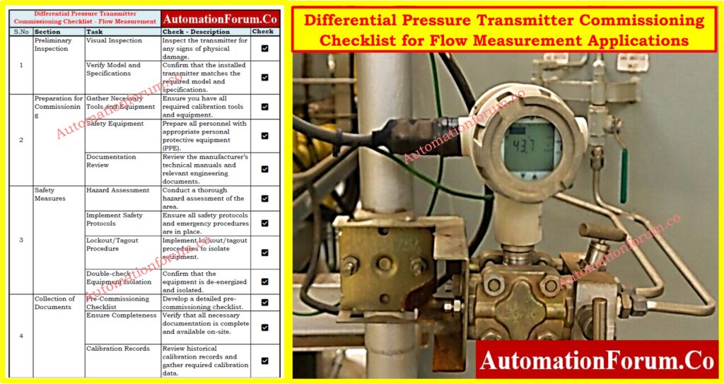
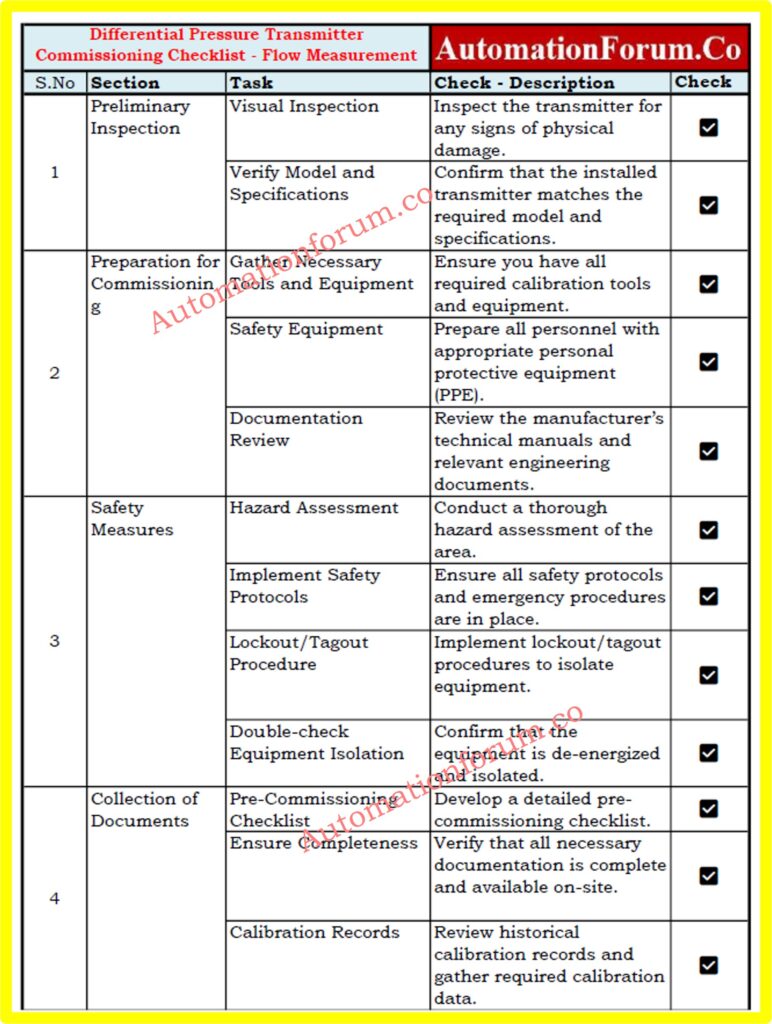
- Differential pressure transmitters are crucial for accurate flow measurement in process plants, particularly when integrated with flow elements such as orifice plates, Venturi tubes, and Annubar sensors.
- Ensuring proper commissioning of these transmitters is essential for reliable and precise flow measurement.
- The differential pressure transmitter commissioning checklist in flow measurement applications includes several key steps that ensure accurate and reliable flow measurement in process plants.
Section :1 Preliminary Inspection
Visual Inspection
- Inspect the transmitter for any signs of physical damage such as dents, cracks, or corrosion. Ensure that the housing is intact and all components are securely fastened.
Verify Model and Specifications
- Confirm that the installed transmitter matches the required model and specifications for the application. Check the nameplate for details like model number, range, and serial number to ensure compatibility with the system.
Section :2 Preparation for Commissioning
Gather Necessary Tools and Equipment
- Ensure you have all required calibration tools, including a handheld communicator, pressure calibrator, and reference standards. Verify that the calibration equipment is calibrated and in good working condition.
Safety Equipment
- Prepare all personnel with appropriate personal protective equipment (PPE) such as hard hats, safety glasses, gloves, and flame-resistant clothing, depending on the plant’s safety requirements.
Click here for Basic Safety and General Consideration While Executing Calibration Process in process industries
Documentation Review
- Review the manufacturer’s technical manuals for detailed installation, wiring, and calibration instructions. This helps ensure that all procedures align with the manufacturer’s recommendations.
- Collect all required diagrams, Instrument Loop Diagram, hook up drawing, instrument data sheet and relevant engineering documents. Understanding the process context helps in accurate setup and calibration.
Section :3 Safety Measures
Hazard Assessment
- Conduct a thorough hazard assessment of the area where the commissioning will take place. Identify potential risks such as high pressure, high temperatures, and hazardous chemicals.
Implement Safety Protocols
- Ensure that all safety protocols, including emergency procedures, are in place and communicated to all team members. Set up safety barriers and signage as needed.
Lockout/Tagout Procedure
- Implement lockout/tagout procedures to ensure that the transmitter and associated equipment are isolated from the process.
- This prevents accidental energization or exposure to hazardous conditions.
- Double-check that the equipment is de-energized and isolated.
- Use appropriate testing methods to confirm that no residual energy is present.
Section :4 Collection of Documents
Pre-Commissioning Checklist
- Develop a detailed pre-commissioning checklist that includes all necessary steps and procedures. This checklist should cover visual inspections, wiring checks, calibration steps, and safety measures.
Ensure Completeness
- Verify that all necessary documentation, including technical manuals, process diagrams, and previous calibration records, is complete and available on-site.
Calibration Records
- Review historical calibration records to understand the transmitter’s performance history and identify any previous issues or adjustments.
- Gather the required setpoint and calibration data, including pressure ranges and span values, to ensure accurate calibration.
Section :4 Verification of Installation
Proper Mounting:
- Ensure that the transmitter is mounted according to the manufacturer’s instructions.
- It should be level, securely fastened, and positioned to minimize the effects of vibration.
- Verify that the transmitter and the flow element (orifice, Venturi, Annubar, etc.) are correctly oriented.
- The flow direction should match the arrow indicated on the flow element and transmitter.
Piping and Connections:
- Check that all process and impulse lines are correctly installed.
- Verify that there are no kinks, sharp bends, or improper fittings that could affect flow or pressure readings.
- Conduct a visual inspection and use leak detection fluid to identify any leaks in the piping and connections.
- Ensure all seals and connections are tight and secure.
Section :5 Wiring and Voltage Checking
Wiring Connections
- Check all wiring connections in the transmitter, ensuring they are correctly terminated and labeled in the local junction box as per diagram.
- Look for any signs of wear or damage to the wires.
- Ensure all terminal screws are securely tightened to prevent loose connections, which could lead to signal loss or erratic readings.
Voltage Verification
- Verify that the transmitter is receiving the correct voltage as specified by the manufacturer.
- Use a multimeter to check the voltage at the transmitter terminals.
- Check for any voltage drops or interference that may affect signal integrity.
- Ensure the power supply is stable and within the specified range.
Section :6 Loop Checking
Signal Loop Verification
- Inject a known signal into the loop and verify that it is correctly received by the control system.
- This ensures that the transmitter’s signal is being properly transmitted and received.
Check Continuity
- Ensure there is continuity in the signal loop from the transmitter to the control system.
- Use a loop calibrator to test the loop signal path and identify any breaks or faults.
Section :7 Commissioning
Zero and Span Calibration
- Gather the required setpoint and calibration data, including pressure ranges and span values, to ensure accurate calibration.
- Apply zero pressure to the transmitter and adjust the zero setting as needed. Ensure the output signal is accurate and stable at the zero point.
- Apply a known pressure equal to the transmitter’s maximum range and adjust the span setting to ensure the transmitter reads accurately at this point.
Linearity Check
- Apply pressure at several intermediate points within the range (e.g., 25%, 50%, 75% of the range) and record the transmitter’s output.
- Ensure the output is linear and within acceptable limits at all points. Any deviations should be within the transmitter’s specified accuracy.
Click here for Step by Step Calibration Procedure for Differential Pressure Transmitter
Section :8 Field Calibration If required
Zero Calibration
- Perform calibration with the process fluid under actual operating conditions and make necessary adjustments to account for process variables such as temperature and pressure.
Signal Verification
- Verify that the transmitter’s output signal matches the expected value for given pressure conditions and ensure the transmitter is properly integrated with the control system and the signal is correctly interpreted.
Installation Check
- Verify that impulse lines are properly filled with the process fluid and free from air pockets, which could cause measurement errors.
- Equalize the pressure in the impulse lines by opening the equalization valve and ensuring both high and low sides are at the same pressure before closing the valve.
Click here for Key Considerations for Pressure Transmitter Manifold Selection
Compare Output Signals
- Compare the transmitter’s actual output with the value displayed in the control system. This helps verify that the control system is accurately interpreting the transmitter’s signal.
- Measure the transmitter’s mA output using a multimeter and compare it with the actual reading in the control room. Ensure that the readings match and are within the expected range.
Section :9 Fail-Safe Function Check
- Induce Failures: Simulate failure conditions such as loss of signal, power failure, or pressure anomalies to check the fail-safe functions of the transmitter.
- System Response: Verify that the control system correctly responds to these failure conditions and takes appropriate action, such as triggering alarms or shutting down processes.
Section :10 Troubleshooting
- Signal Drift: Check for signal drift and recalibrate if necessary. Drift can be caused by environmental factors or component aging.
- Blockages and Leaks: Inspect for blockages or leaks in the impulse lines and rectify any issues found. Ensure all connections are tight and sealed.
- Diagnostic Software: Use manufacturer-provided diagnostic software or tool(like Hart Communicator) to identify and troubleshoot issues. This software can provide detailed information on transmitter performance and fault conditions.
- Error Codes: Interpret and address any error codes displayed by the transmitter. Refer to the manufacturer’s manual for guidance on resolving specific error codes.
Click here for Troubleshooting of DP Type Flow Measurement
Section :11 Reporting and Completion Process
Documentation
- Calibration Records: Document all calibration and commissioning activities, including settings, adjustments, and measurements. Keep detailed documents for audits and future reference.
- Final Report: Prepare a comprehensive final report summarizing the commissioning process, findings, and any recommendations. Include photographs, diagrams, and relevant data.
Sign-Off
- Approval: Obtain sign-off from relevant personnel, including instrumentation engineers, process engineers, and safety officers.
- This ensures that all stakeholders are satisfied with the commissioning process.
- Handover: Handover the transmitter to the operations team with all relevant documentation and instructions.
- Provide training if necessary to ensure proper operation and maintenance.
Section :12 Adhering to Standards and Regulations
Industry Standards
- Ensure compliance with relevant industry standards such as ISA (International Society of Automation) and IEC (International Electrotechnical Commission). Follow best practices and guidelines for instrumentation and control.
- Follow the manufacturer’s guidelines and recommendations throughout the commissioning process. This ensures that the transmitter is used and maintained correctly.
Click here for Understanding the Working Principle of Multivariable DP Mass Flow Transmitters
Regulatory Requirements
- Adhere to local regulatory requirements, including health, safety, and environmental regulations. Ensure that all activities are conducted in a safe and compliant manner.
- Maintain thorough documentation to demonstrate compliance with all applicable standards and regulations. This is crucial for audits, inspections, and maintaining operational integrity.
Downloadable Differential Pressure Transmitter Commissioning Excel Checklist for Flow Measurement Applications
Differential pressure transmitters are essential for accurate flow measurement in process plants. To help ensure these transmitters are properly commissioned, we’ve created an easy-to-use checklist in Excel format. Click on the below link to download.