- 7 Steps Calibration Procedure for DP Transmitter
- Step 1: Prepare Tools required for DP transmitter Calibration
- Step 2: Safety Precautions
- Step 3: Prepare the Calibration Setup for DP transmitter Calibration
- Step 4: Calibration of Differential Pressure Transmitter
- Step 5: Recording Calibration with Linearity Checks
- Step 6: Completion of Calibration
- Step 7: Calibration Report Preparation
- Calibration Procedure: Aligned with NIST and IEC 61508 Standards for DP Transmitter
What is a DP transmitter?
Differential pressure is represented by “DP”. The difference in pressure between two points in a process is measured by a DP transmitter, which then translates the data into a standard output signal (often 4-20 mA) for processing or transmission to a control system.

DP transmitters generally include two pressure sensing components, one on each side of a flexible membrane such as a diaphragm. A strain gauge or other sort of pressure sensor detects the membrane’s deflection, which is caused by the pressure differential between the two parts. The electronics in the transmitter then process the sensor’s output signal to create a standardized output signal.
What is DP transmitter used for?
Industrial applications include process control, flow measurement, level measurement, and pressure monitoring often employ DP transmitters. For measuring complicated processes, they are often used in combination with other instruments like flowmeters or level sensors.
A differential pressure (DP) transmitter is most often used in industrial applications to determine and monitor the flow, level, and pressure of liquids, gasses, and vapors.
A DP transmitter is used to measure the difference in pressure between the liquid or gas at the bottom of a tank or vessel and the pressure at the top of the tank or vessel. This is done in level measurement applications. The amount of the liquid or gas in the tank or vessel determines how much of a pressure differential there is.
A DP transmitter is used to detect the pressure differential over an obstruction, such as an orifice plate, venturi meter, or flow nozzle, in flow measurement applications. This pressure differential is proportional to the liquid or gas flow rate passing through the obstruction.
A DP transmitter is used to monitor the pressure differential between two points in a pipeline or vessel for pressure measurement applications. You may determine the absolute or gauge pressure at either place using this pressure differential.
Overall, DP transmitters are a popular option for a variety of industrial applications due to their flexibility and precision.
How do you calibrate a DP transmitter?
7 Steps Calibration Procedure for DP Transmitter
This below Step by Step calibration procedure provides a thorough explanation of how to calibrate a DP Transmitter using reference standards in workshop
Step 1: Prepare Tools required for DP transmitter Calibration
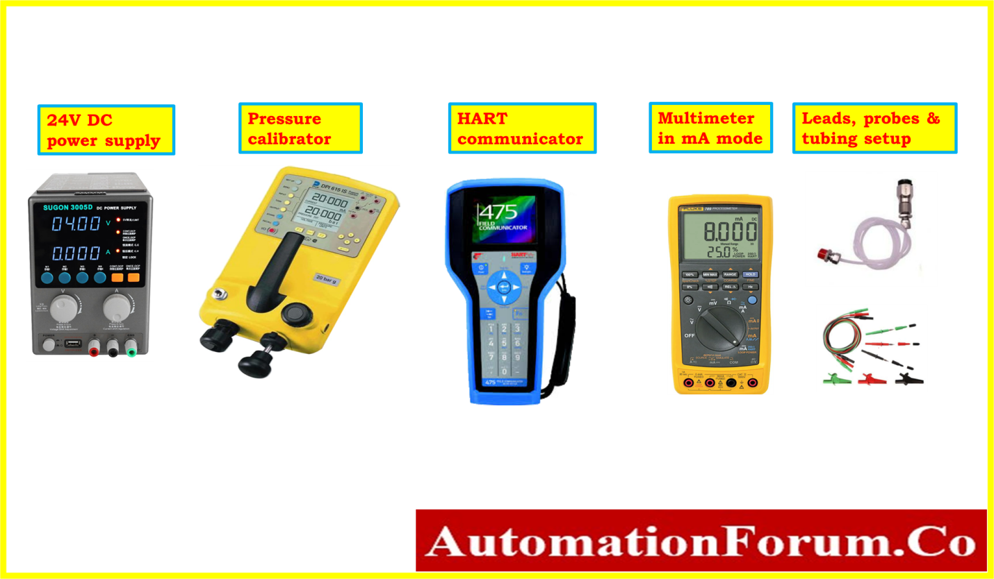
- Necessary hand tools.
- 24 V power supply source.
- Standard Pressure Calibrator.
- Standard Multimeter.
- Test leads and probes.
- Tubes and standard fittings
- Soft Cloth for cleaning.
- Communication tool is necessary, such as a Hart communicator if it is a smart transmitter.
Step 2: Safety Precautions
- For specifics on basic safety, general recommendations, and calibrating operations in process industries, please click the link provided below. Basic Safety and General Considerations for Process Industries Calibration Process
- Ask the panel operator to set the controller in manual mode for the control loop and MOS for the ESD loop.
- Locate the DP transmitter you want to turn off. Make sure that the DP transmitter is the right one and record any key information, such as the Tag number (e.g., the manufacturer, model number, pressure range, etc.).
- Be sure there is no pressure or fluid flowing through the instrument before removing the DP transmitter by isolating the process.
- The pipe connecting the DP transmitter to the process should be closed or disconnected. As a result, the transmitter will be separated from the process and no fluid will seep out.
- By releasing the bleed valves or vent valves on the transmitter, you may release any pressure that could have been trapped within the transmitter.
- Disconnect the power supply from the DP transmitter. Ensure that any nearby junction boxes or marshalling panels adjacent to the control room have their power sources switched off. (For instance, turn it off or disconnect the cable).
- Remove the DP transmitter from its mounting bracket after removing the cabling. Remove the transmitter by unscrewing the bolts or nuts that hold it to the bracket.
- To stop any fluid from seeping out once the transmitter has been removed, plug the lines.
- Keep the DP transmitter in a secure place where it will not be harmed.
- After removing the DP transmitter, label it with any relevant info (such as the date, the reason for removal, and so on) and store it safely. In order to prevent contamination or damage, keep the DP transmitter carefully if it has to be reinstalled.
- While removing a DP transmitter from the field, it’s crucial to follow the manufacturer’s instructions and any necessary safety precautions. To ensure that the removal is done safely and properly, it may also be beneficial to discuss with a skilled technician or engineer.
- Follow all relevant lockout/tagout procedures to prevent an unintended start. Ensure that the DP transmitter is isolated from the process.
Step 3: Prepare the Calibration Setup for DP transmitter Calibration
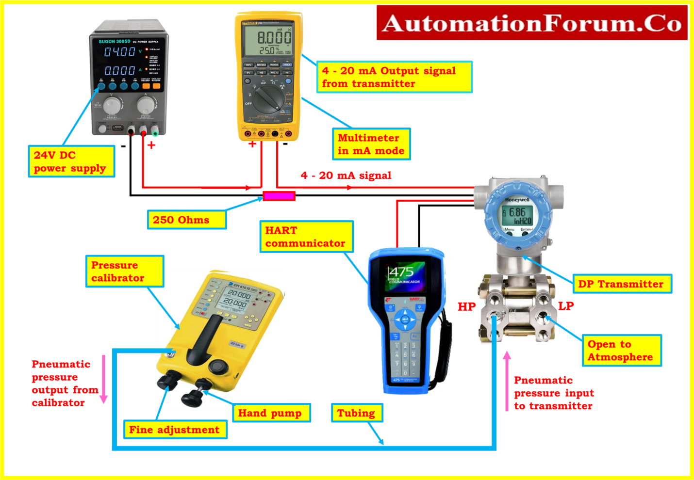
- The calibration equipment needs to be put in a place that doesn’t have any vibrations or electromagnetic interference. In addition, the place must be well-ventilated and light.
- The test bench has to be clean, solid, and level.
- Install the transmitter on the test bench with stand.
- One end of the tube should be connected to the high pressure side (HP) side of the DP transmitter, and the other end should be attached to the output of the pressure calibrator. Check the connections to make sure they are tight and leak-free.
- The low-pressure side (LP) of the transmitter is always maintained with an open vent to the surrounding atmosphere.
- The transmitter and the 24-volt power supply are connected in series with a digital multimeter equipped to measure milliampere current. Also connect the 250 ohms resistance series with the transmitter for impedance matching.
- Attach the HART communicator to the DP transmitter’s terminal.
Step 4: Calibration of Differential Pressure Transmitter
- Make sure that the output wire connections and input tubing connections on the DP transmitter are secure.
- Set the power supply unit to 24 v dc to turn on the DP transmitter. Before turning on the circuit, use a multimeter to verify the voltage level in the power supply output.
- The pressure calibrator should be turned on now.
- Consult the datasheet for the DP transmitter and make sure in the pressure calibrator’s menu is set to the correct unit.
- Set the transmitter’s 0% Lower Range Value (LRV) to the LRV of the calibration range.
- Set the upper range value (URV) of the calibration range for the transmitters’ span to 100%.
- As an example, the transmitter’s 0% LRV is 4mA and it is calibrated to 0 psi if you are using a differential pressure transmitter with a power output of 4-20mA to monitor pressure in the range 0-50 psi. The 100% URV is 20mA and will be calibrated to 50 psi similarly.
- Consult the instruction manual to find the transmitter’s ZERO and SPAN/RANGE adjustments in the display menu.
- Apply the LRV 0% on the high side of the transmitter by pressure calibrator, and 0% on the low side that is vented.
- While focusing on the 4mA reading on the multimeter, adjust the ZERO adjustment menu in display or zero adjustment potentiometer of the transmitter. This is your transmitter’s LRV output.
- Then, apply pressure to the high side of the transmitter to raise the reading to the calibration range’s 100% higher value (URV).
- While focusing on the 20mA reading on the multimeter, adjust the SPAN adjustment menu in display or SPAN adjustment potentiometer of the transmitter. This is your transmitter’s URV output.
- For SMART transmitters, we must use a HART communicator. After connecting the communicator and the transmitter, choose the lower range value trim and higher range value trim options from the HART Communicator Menu.

- You will need to perform the method of calibration as many times as necessary until the DP transmitter is calibrated to the appropriate tolerance.
- Depending on the specific pressure calibrator and DP transmitter being used, the calibration process may change. As a result, please make sure you follow the instructions provided by the manufacturer before starting up.
Step 5: Recording Calibration with Linearity Checks
- Do linearity tests in the upscale and downscale directions at 0%, 25%, 50%, 75%, and 100% to make that the DP transmitter is producing the correct output values.
- If the output value does not fall within an acceptable range, calibration is required. Once again, if the output values have deviated from the allowed range, a DP transmitter must be serviced or replaced.
- No extra calibration is required if every output value (+/- %) falls within acceptable bounds.
- The output data should be entered into the as found/as left column of the blank calibration report.
Note: Consistent linearity testing and dedicated collection of calibration data are required for maintaining the DP Transmitter’s accuracy and reliability over time.
Step 6: Completion of Calibration
- When the calibration has been successfully completed, attach the calibration label to the DP transmitter.
- When the calibration is complete, clean the instrument, store it somewhere safe, and record the calibration data for later use.
- Disconnect the DP transmitter, pressure calibrators, and other setup.
- The DP transmitter should be fixed back in the processing area.
- Make sure the workplace is clean.
- De-isolate the equipment.
- Return the bypassed or inhibited signal to its original level.
- Make that the DP transmitter is working correctly before resuming use of it.
Step 7: Calibration Report Preparation
The following image demonstrates how the calibration of the DP transmitter sample report was completed in a workshop using a pressure calibrator and multimeter as the reference.
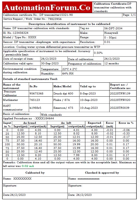
The link below gives you access to the Excel template that was used to create the DP transmitter calibration report.
Calibration Procedure: Aligned with NIST and IEC 61508 Standards for DP Transmitter
Follow our differential pressure (DP) transmitter calibration procedure to ensure accurate and reliable signal transmission, as well as to improve industrial performance. This method was carefully designed in accordance with the National Institute of requirements and Technology (NIST) requirements.
The International Electrotechnical Commission (IEC) 61508 specifies safety requirements for electrical systems in essential industries. Conforming to its calibration methods is critical for safe and accurate differential pressure measurement. To ensure safety in DP transmitters, the methodical approach offered by IEC 61508 throughout the system’s lifecycle is essential.