How does a magnetostrictive sensor work?
Magnetostrictive level transmitters are continuous float level sensors that measure level in almost real-time by using two opposing magnetic fields to create a signal that corresponds to the level of liquid.
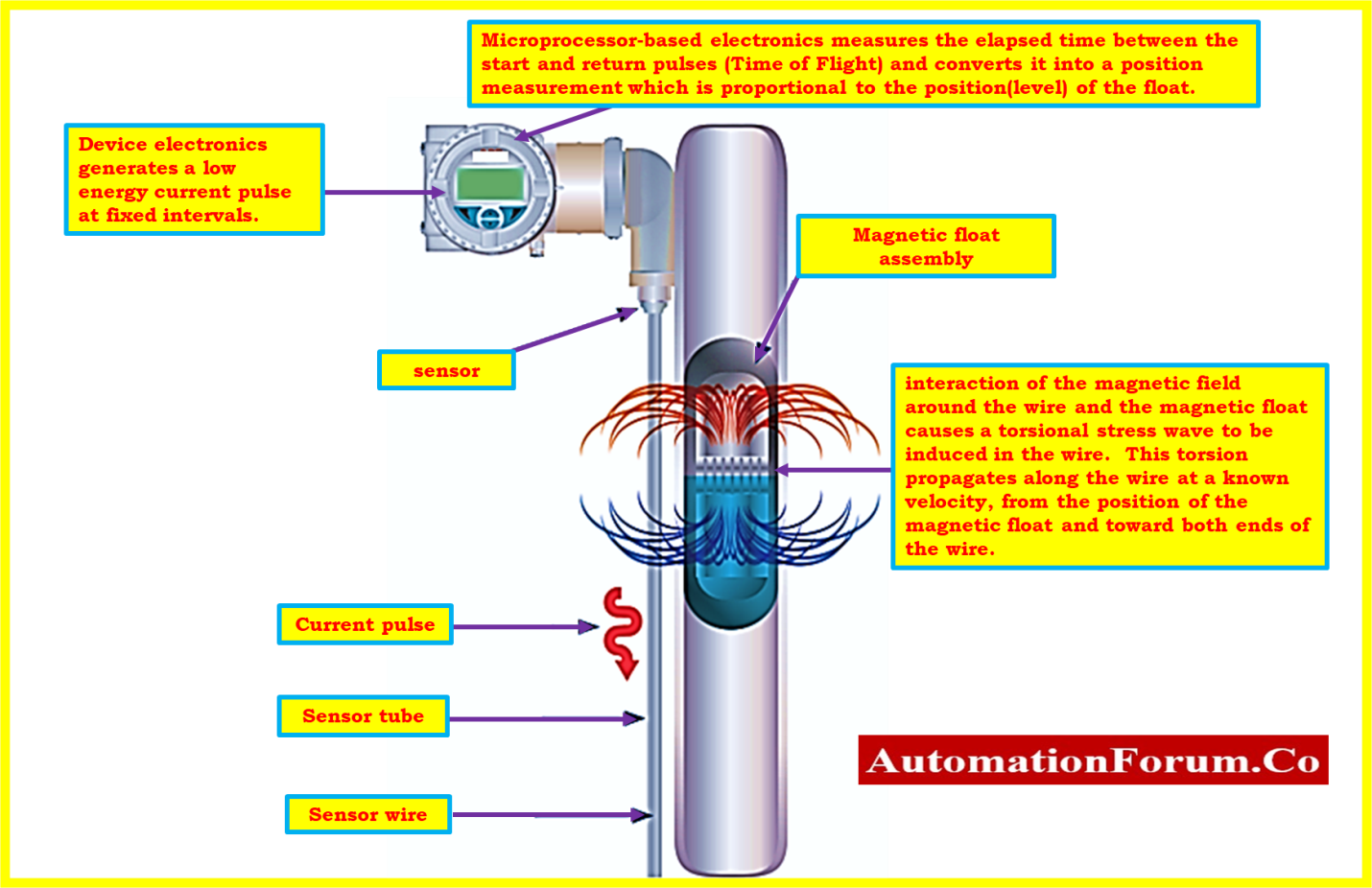
Magnetostrictive float level measurement sensors are made up of three major components. In the fluid being monitored, a hollow stem with a waveguide constructed of ferromagnetic material is suspended.
Along with the liquid’s surface, a hollow float travels up and down the stem. A permanent magnet is embedded inside this float.
As the float travels, its magnetic field modifies the alignment of the magnetic molecules in the stem’s waveguide.
The electronics of the device make up the third element. The electronics produce an electromagnetic pulse at regular intervals. When it moves through the waveguide, this pulse generates a magnetic field of its own. Conflicting magnetic fields in the waveguide cause vibrations when this pulse hits the float, which causes a torsional stress wave, also known as a strain pulse, to go back up the waveguide at a predetermined rate.
A part of the electronics that transforms mechanical energy into an electronic signal is what senses the strain pulse. The distance between the device electronics and the float is then accurately determined by measuring the interval between the initial pulse and the returning strain pulse using an electronic chip.
Purpose and Scope:
This procedure contains instructions for calibrating a magnetostrictive level transmitter that has been calibrated with process liquid in the process area.
Calibration principle:
- It is a two-point straight line method. The transmitter extends the straight line beyond the calibration locations at both ends.
- The range of the High and Low calibration points is 0% (tank empty) to 100% of the overall range (tank full).
- Two calibration points should be as far apart as possible for maximum accuracy. It is crucial that the low calibration point be set at a lower level than the high calibration point.
- The output current must be adjusted so that it matches the actual level at two independent calibration points in order to calibrate the device.
Tools required for Calibration:

- Necessary hand tools.
- Multimeter.
- Standard Measuring tape.
- Test leads and probes.
- Soft Cloth for cleaning.
Safety
- Please click the following link for more information on basic safety, general recommendations, and calibrating operations in process industries.
Calibration Process for Process Industries: Basic Safety & General Factors
- Send a message to the DCS or the panel operator instructing them to employ the MOS (Maintenance Override Switch) for the ESD loop and manual mode for the Magnetostrictive Level Transmitter control loop.
- Identify the Magnetostrictive Level Transmitter that needs calibration. Make sure it’s the appropriate level transmitter by checking, and record any special information Tag number (e.g., the manufacturer, model number, pressure range, etc.).
- Do not disconnect the Magnetostrictive Level Transmitter’s power supply. Check to see if the power source is present at any junction boxes or marshalling panels close to the control room with instrument loop diagram.
- Keep in mind that depending on the particular equipment and process location, this overall technique may need to be adjusted. When dealing with a magnetostrictive level transmitter or other process equipment, always adhere to any manufacturer’s instructions and local safety standards.
- To avoid an unintended start, adhere to all applicable lockout/tagout protocols. Remember to keep the Magnetostrictive Level Transmitter independent of the operation.
Calibration Setup
- Electromagnetic interference and vibrations must not exist in the process region where the calibration equipment is placed. Also, the area needs to be well-ventilated and illuminated.
- Assemble all of the equipment and tools required.
- You must make sure that the proper control measure is carried out in the event that the calibration method poses a risk in order to completely eliminate it.
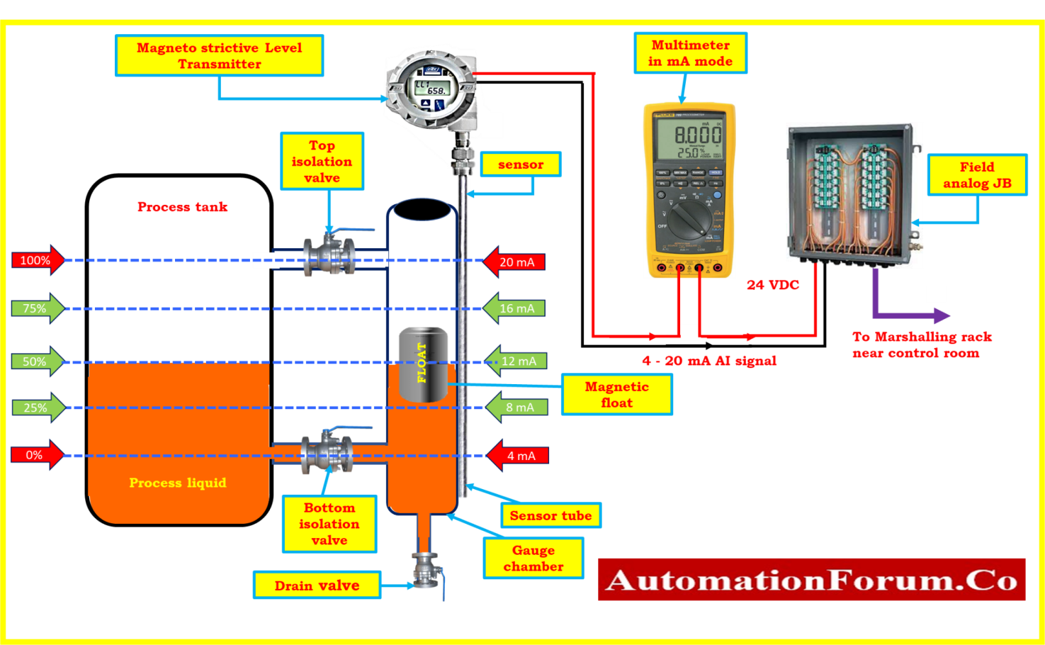
- Use probes and a lead to connect the multimeter (mA mode) in series with an analogue input loop between the junction box and the magnetostrictive Level Transmitter.
- If the magnetostrictive level transmitter is smart, you should also connect the HART field communicator to the terminal for the magnetostrictive level transmitter.
- As indicated in the above diagram, the connections have been established and are currently being readied for the calibration of the magnetostrictive level transmitter.
Calibration procedure
- Verify to determine if the magnetostrictive level transmitter connections are stable.
- Verify that the magnetostrictive level transmitter terminal has a 24 VDC power supply.
- You will be able to verify a few of the parameters with the help of the data sheet that is included with the magnetostrictive level transmitter. Examples of usual parameters are the tag number, PV, LRV, and URV.
- You may use a hart communicator to verify the parameters if it’s a smart magnetostrictive level transmitter.
- By using a standard measuring tape, the calibration points for the reference level from the data sheet should be marked on the gauge chamber of the magnetostrictive level transmitter.
- In the case there’s a calibration point marking, the same should be verified using a standard measuring tape.
- A certain type of magnetostrictive level transmitter often comes with an external level scale mark on the exterior of the gauge chamber.
- To drain the fluid from the chamber, close the top and bottom isolation valves connected to the magnetostrictive level transmitter’s gauge chamber and open the drain valve.
- The drain valve should now be closed, and the chamber of a magnetostrictive level transmitter gauge should be manually filled with process fluid through the bottom isolation valve until it reaches the 0% percentage mark on the chamber.
- You should now look at the multimeter, which should be showing a 4mA output from the magnetostrictive level transmitter.
- Locate the zero adjustment option on the magnetostrictive level transmitter display and make the appropriate changes there until the reading reads 4mA. Alternatively, you may utilize the HART Communicator to make the adjustments for smart magnetostrictive level transmitter.
- The bottom isolation valve of a magnetostrictive level transmitter gauge should be opened to manually fill the chamber with process fluid until the chamber reads 100%.
- Now check the multimeter; it should display a 20mA output from the magnetostrictive level transmitter.
- On the magnetostrictive level transmitter display, find the span adjustment option, and make the necessary adjustments there until the readout reads 20 mA.

- When filling the gauge chamber with fluid, you must ensure that the magnetic float moves very smoothly and that the output of the transmitter is increasing gradually in accordance.
- If it is not possible to establish the level in the gauge chamber using the process fluid, then move the magnetic float to the desired calibration point.
- Make sure that the mounting clamps for the magnetostrictive level transmitter sensor are secure and tight before making any adjustments.
- You can move the transmitter sensor using sensor mounting clamps if you have linear error in the zero and span calibration points.
- Repeat the calibration procedure for the magnetostrictive level transmitter as much as required until it is calibrated to the necessary tolerance.
- The calibration process might need to be modified depending on the magnetostrictive level transmitter that is being installed in the process. Therefore, before beginning, please read the manufacturer’s instructions for the magnetic level transmitter.
Recording calibration
- Make sure that the magnetostrictive level transmitter is delivering the right output values by performing linearity checks at 0%, 25%, 50%, 75%, and 100% fluid level output in the upscale and downscale directions.
- Calibration is necessary if the output value does not fall within an acceptable range. Again, the magnetostrictive level transmitter has to be repaired or replaced if the output values have deviated from the acceptable range.
- There is no need for additional calibration if the magnetostrictive level transmitter’s output values (+/-%) fall within acceptable tolerances.
- The blank calibration report’s as found/as left column should be filled in with the output data.
Completion of calibration
- Attach the calibration label on the magnetostrictive level transmitter once the calibration has been correctly completed.
- As soon as the calibration is finished, clean the test instrument, put it in a secure location, and record the magnetostrictive level transmitter calibration data for future use.
- Magnetostrictive level transmitter calibration setup and the other setup should be disconnected.
- Ensure that the workspace is clean.
- De-isolate the equipment.
- restore the blocked or bypassed magnetostrictive level transmitter signal to its original state.
- In the ESD loop, the MOS needs to be normalized.
- Restart the magnetostrictive level transmitter and make sure it is operating properly.
Sample magnetostrictive level transmitter report
The picture below shows a magnetostrictive level transmitter calibration sample report that was performed in a process zone.

The Excel template that was used to construct the calibration report for the magnetostrictive level transmitter can be downloaded by clicking the link below.