- How Cavitation Happens in a Control Valve
- What is a cavitation number?
- What are the stages of cavitation in a valve?
- How to avoid cavitation in the control valve?
- How do we manage the cavitation in control valves?
- Why does cavitation occur in a control valve?
- How does cavitation affect your control valves?
- What is Cavitation damage?
- How to prevent cavitation with staged pressure-reducing trim?
- Signs of Cavitation in a Control Valve
- Cavitation vs Flashing
- How to Reduce Cavitation Damage
- Sigma and Cavitation Prediction
- Best Practices for Control Valve Selection
- FAQ on Cavitation in a Control Valve
How Cavitation Happens in a Control Valve
- Cavitation is a phenomenon that occurs in a control valve during sizing control valves for liquid flow applications.
- Cavitation in the valve occurs in fluid flow systems where the local static pressures are below the fluid’s vapor pressure.
- According to the Bernoulli equation the cavitation in the valve occurs when a fluid accelerates in a control valve or around a pump impeller.
- Cavitation is common in pumps and control valves that cause serious wear and tear, and damage.
- Cavitation may cause severe damage to control valves and reduce their lifespan under the wrong conditions.
- Cavitation is a two-phase process that occurs in flowing fluids under certain flow conditions.
- The cavitation in a control valve is easily studied by considering the valve as an orifice plate in a pipe.
- The valve cavitation has low intensity, and low frequency.
- Valve characteristics also contribute to valve cavitation.
- When the fluid flows through the narrow constriction of the valve trim of the control valve the fluid velocity inside the valve trim increases.
- And in the downstream or output side of the valve trim, the fluid velocity decreases because of the wider area.
- It causes the pressure drop due to the principle of conservation of energy.
- The pressure also changes velocity when the fluid is passed through the control valve.
The below schematic representation shows the change in pressure and velocity of the fluid flowing through the control valve that results in cavitation.
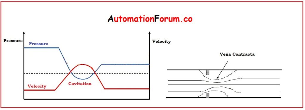
The kinetic energy of the fluid is changed as the velocity of the fluid.
The kinetic energy is given as

In a moving stream, the energy of the fluid is conserved, in the form of fluid pressure, as the fluid velocity increases the KE is increased which is followed by a complementary decrease in PE.
At this point, the reduced pressure and higher velocity along the flow stream are known as Vena Contracta. In vena contracta, the fluid pressure is at its minimum level.
The cavitation takes place when the fluid pressure at the vena contracta drops below the liquid vapor pressure.
Vena contracta is located close to downstream of the valve orifice.
What is a cavitation number?
The cavitation number is the ratio between static pressure and the vaporization pressure of the fluid.
What are the stages of cavitation in a valve?
Cavitation in a valve occurs in two stages.
1. First stage:
When the fluid pressure drops below the liquid vapor pressure, the vapor bubbles are formed in the liquid. These vapor bubbles interrupt the continuity of the fluid flow through the valve.
2. Second stage:
Pressure recovery after the vena contracta raises the pressure above the liquid and the vapor pressure causes the collapsing of the bubbles and causes damage to the valve.
The collapsing of vapor bubbles causes high-pressure shocks for about 150K PSI.
These pressure shocks cause cracks on the surface of the materials. The surfaces of the material that are damaged by cavitation are always rough and spongy.
Cavitation affects physical damage to the valve and downstream side of piping, instruments, and other equipment by producing noise of high levels and vibration.
How to avoid cavitation in the control valve?
Cavitation effect in the control valve is avoided by:
- Re-engineering the components initiating for high velocities and low static pressure.
- Cavitation and valve damage can be avoided by using some special components that are designed for rough conditions with max pressure drop handled by multi-stage control valves.
- Increasing the static pressure of the system. An increase the actual distance between the static pressure and the vaporization pressure and avoids cavitation as well as vaporization.
- Reducing fluid temperature or locating components in the cooler regions of systems.
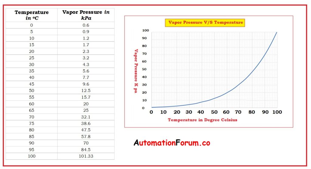
- The vaporization pressure depends on the temperature of the flowing fluid
How do we manage the cavitation in control valves?
Generally, avoiding the cavitation in the control valve is not always possible
But cavitation in control valves can be managed by
- Using special valve trim designs for controlling the pressure drop and reducing fluid velocity.
- Ensure that the fluid pressure must not fall below the vapor pressure.
- Control valve trims must be kept away from unprotected or vulnerable components.
- Control where bubbles collapse.
- Make sure that the plug and seat are made from damage-resisting materials like stainless steel.
- Stellate or tungsten carbide surfaced materials are used in the impact regions.
- Use multistage control valves or multiple control valves so that the pressure drop in the valve occurs gradually known as pressure drop staging.
- The control valve should be installed at a lower elevation.
- Fix the control valve in the lower temperature area of the fluid.
- Special valve trim methods using disk stack technology for severe duties in which the flowing energies are distributed through the valve trim into multiple levels of disks containing exit flow paths.
Why does cavitation occur in a control valve?
Cavitation in control valves occurs due to
- Variation in velocity of the flowing fluid.
- The fluid in the valve accelerates rapidly
- The pressure drop in the valve exceeds a critical point
- Downstream pressure exceeds the fluid vapor pressure.
How does cavitation affect your control valves?
Cavitation in a control valve is common, but most control valves are built to resist the effect of cavitation for a limited period.
When the vapor bubbles get collapsed an implosion is created that causes a pit in the valve material. At this time wear and tear results in severe erosion that causes the valve to fail.
Predicting Cavitation in Control Valves:
- Cavitation in control valves occurs only for liquid medium.
- The principal factors for cavitation are fluid velocity and pressure drop.
- Vapor bubbles are formed if the upstream pressure of the liquid drops below vapor pressure as the fluid flows through the valve.
- Cavitation is the collapsing of vapor bubbles as the pressure recovers downstream of the valve’s trim outlet.
- Sigma is the most widely accepted and precise cavitation index used to quantify and predict cavitation in control valves.
- For the formation of vapor bubbles the sigma factor is represented as the ratio of the potential for resisting to the potential for causing.
- Sigma factor = potential for resisting / potential for causing.

Where
P1 = upstream pressure
P2 = downstream pressure
PV = Vapor pressure.
| ? < 1.0 | No Cavitation |
| 1.7 <? < 2.0 | Hard trim provides sufficient protection |
| 1.5 <? < 1.7 | Some cavitation, single stage trim may work |
| 1.0 <? < 1.5 | Potential for severe cavitation, multi-stage pressure drop trim required. |
| ? < 1.0 | Flashing |
What is Cavitation damage?
- Cavitation damage is a hyper erosion that destroys both piping and control valves.
- This results in undesirable process failures.
- The vapor bubbles created by pressure drop will collapse and rebound.
- And the vapor returns to liquid form. The breakdown of vapor bubbles in the cavitation phenomenon will force the damage in the form of small pits in the metal surfaces.
How to prevent cavitation with staged pressure-reducing trim?
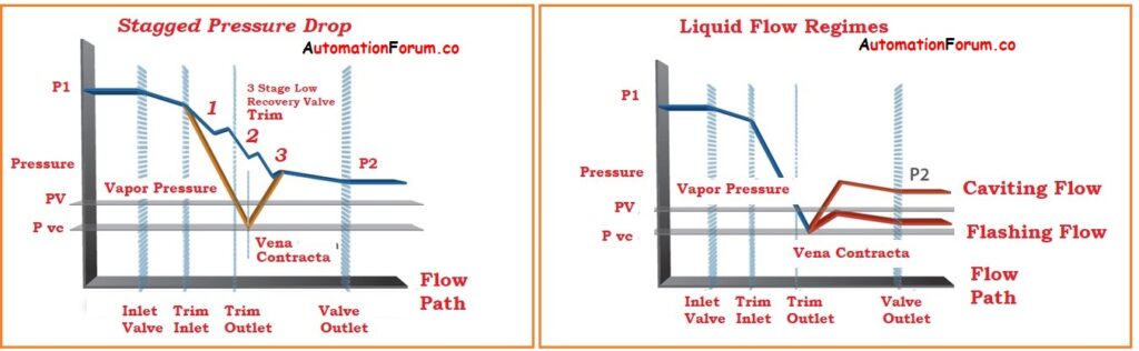
Cavitation with staged pressure reducing trim can be prevented by
- Applications with more severe cavitation of 1.0 < ? < 1.5
- The pressure from the trim inlet to the trim outlet is reduced gradually.
- By staging a pressure reduction method the trim avoids the pressure dipping below the vapor pressure and prevents the generation of vapor bubbles that damages the valve.
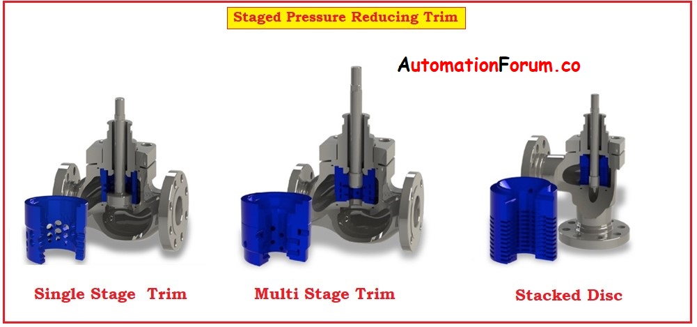
- Single-stage trim: Single stage is a cost-effective trim and reduces the valve and piping cavitation damage by diverting the location to an area away from metal parts and controlling the concentration of vapor bubbles.
- Multi-Stage trim: Multi-Stage trim reduces the pressure through a series of restrictive channels and expansion areas. Multi-Stage trim prevents cavitation and eliminates cavitation damage from occurring altogether.
- Stacked Disc: Stacked Disc trim is the most powerful solution designed to block the most critical pressure drop. Reduces the sound levels and eliminates the effects of cavitation.
Signs of Cavitation in a Control Valve
The common signs of cavitation are loud crackling or gravel-like noise, strong vibration, unstable control, and visible damage on the valve trim. Over time, the repeated collapse of bubbles can cause pitting, erosion, and material loss on metal surfaces
Cavitation vs Flashing
Cavitation and flashing are not the same. In cavitation, the vapor bubbles collapse after pressure recovery. In flashing, the downstream pressure stays low enough that the liquid remains partially vaporized, so the bubbles do not fully collapse. Cavitation is usually more damaging because of the violent implosion of the bubbles
How to Reduce Cavitation Damage
If cavitation cannot be fully eliminated, the goal is to manage it safely. Use hardened trim materials such as tungsten carbide or other wear-resistant alloys, keep critical surfaces away from the impingement zone, and use staged pressure reduction so the energy is distributed over several restrictions instead of one
Sigma and Cavitation Prediction
The sigma index is commonly used to estimate cavitation risk in control valves. In simple terms, it relates the available pressure margin to the pressure conditions that can cause vapor formation. A lower sigma value means a greater risk of cavitation, while a higher value means better protection.
Best Practices for Control Valve Selection
For liquid applications with high pressure drop, the valve should be sized carefully and checked for cavitation risk during selection. If the service is severe, anti-cavitation trim or a multi-stage pressure reduction design is usually a better choice than a standard single-stage trim. Proper sizing, correct material selection, and the right trim design all improve reliability.
Cavitation in a control valve happens when liquid pressure falls below vapor pressure and then recovers downstream, causing vapor bubbles to form and collapse. This collapse creates noise, vibration, erosion, and serious trim damage. The most effective protection is proper valve sizing, pressure-drop control, and the use of anti-cavitation or multi-stage trim for severe liquid service.
FAQ on Cavitation in a Control Valve
What causes cavitation in a control valve?
Cavitation is caused by a local pressure drop below the liquid vapor pressure, usually at high velocity through the valve restriction.
How do you stop cavitation?
Use staged pressure reduction, anti-cavitation trim, hardened materials, and proper valve sizing to reduce the chance of bubble collapse damage.
Does cavitation occur in gas control valves?
No, cavitation occurs only in liquid flow. In gas systems, the phenomenon is different and does not involve vapor bubble formation and collapse.
Where does cavitation occur inside a control valve?
Cavitation typically occurs at the vena contracta, which is the point of highest velocity and lowest pressure inside the valve.
What is the vena contracta in a control valve?
Vena contracta is the location inside the valve where the flow area is minimum, velocity is maximum, and pressure is at its lowest level.
What is the difference between cavitation and choking?
Cavitation is related to vapor bubble formation in liquids, while choking occurs when the flow rate reaches a maximum limit due to sonic velocity conditions (mostly in gases).
Can cavitation damage piping as well as valves?
Yes, cavitation can damage downstream piping, fittings, and instruments due to vibration and repeated shock waves from collapsing bubbles.
What type of valves are more prone to cavitation?
Globe valves and high pressure recovery valves are more prone to cavitation because they create a large pressure drop across the valve.
How do anti-cavitation trims work?
Anti-cavitation trims reduce cavitation by dividing the pressure drop into multiple stages and controlling fluid velocity, preventing pressure from dropping below vapor pressure.
Can cavitation be completely eliminated?
In many industrial applications, cavitation cannot be completely eliminated, but it can be controlled and minimized using proper valve selection and trim design.
What is the effect of temperature on cavitation?
Higher fluid temperature increases vapor pressure, which makes cavitation more likely to occur.
How can I detect cavitation in a running system?
Cavitation can be detected by unusual noise (like gravel sound), vibration, fluctuating flow control, and inspection of valve trim damage.
What materials are used to resist cavitation damage?
Materials such as stainless steel, Stellite, and tungsten carbide are commonly used to resist cavitation damage in control valves.
Is cavitation always harmful?
Yes, in control valves cavitation is generally harmful because it leads to mechanical damage, noise, and reduced performance.