How to calibrate Dp level bubbler type
Calibration procedure:
*Ask panel man to put the controller in manual mode for control loop and to put it on MOS for ESD loop.
*Hook up HART Communicator and verify some parameters by refer to data sheet. Typical parameters are, tag number, PV, LRV and URV.
*Isolate the instrument from the process and the purge system.
WARNING – If the process is hazardous, please unsure proper flushing is done to remove the entire hazard.
Remove the tubing connection at manifold to the process after released the process pressure
*Connect pressure calibrator to high side of the manifold
*Expose the low side to atmosphere
*Hook up a multimeter in series with the signal to the DCS to measure current signal.
*Apply pressure as per data sheet LRV
Multimeter should show 4mA
If not, do zero adjustment at transmitter using HART Communicator
*Apply pressure as per data sheet URV
Multimeter should show 20mA
If not, do span adjustment at transmitter using HART Communicator
*Verify the linearity by increasing and decreasing the pressure (0%,25%,50%,75%,100%,75%,50%,25% and 0%of range)
*After completion of the job ask panel operator to put loops back in normal mode or normalize the MOS
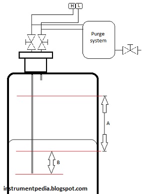
Example calculation
S.G=0.89
A= 2000mm (measurement length)
B = 100mm (off set)
Dp = pressure at high side – pressure at low side
LRV = ( B x S. G) – pressure at low side
= (100mm x 0.89) – 0
= 89 mmH2O
URV = ((A+B) x S.G) – pressure at low side
= (2100mm x 0.89) – 0
= 1869 mmH2O
Related posts:
Differential pressure level transmiiter
Differential pressure flow transmitter
Flow transmitter pitot tube
Control valve calibration