
- Why Is My Thermocouple Reading Wrong Temperature After Replacement?
- Common Symptoms of Incorrect Thermocouple Readings After Replacement
- Thermocouple Reading Too High
- Thermocouple Reading Too Low
- Negative Temperature Reading
- Fluctuating Temperature Reading
- Thermocouple Reading Stuck at One Value
- Gradually Drifting Temperature Reading
- Temperature Changes When the Cable Is Moved
- Intermittent High Temperature Alarms
- Temperature Controller Instability
- False Process Trips Due to Incorrect Temperature
- Step by Step Troubleshooting Procedure for Thermocouple Reading Wrong Temperature After Replacement
- Step 1 Review Maintenance History
- Step 2 Verify the Correct Thermocouple Type
- Step 3 Confirm the Thermocouple Part Number
- Step 4 Verify the Sensor Insertion Length
- Step 5 Check the Thermocouple Installation Location
- Step 6 Inspect the Mounting Arrangement
- Step 7 Verify Proper Process Immersion
- Step 8 Inspect the Thermocouple Extension Cable
- Step 9 Verify Thermocouple Cable Polarity
- Step 10 Inspect Terminal Connections
- Step 11 Check for Loose Terminal Connections
- Step 12 Inspect Moisture Inside the Terminal Head
- Step 13 Verify Temperature Transmitter Configuration
- Step 14 Confirm DCS Input Configuration
- Step 15 Verify PLC Input Scaling
- Step 16 Check Compensation Settings
- Step 17 Verify Cold Junction Compensation
- Step 18 Measure the Thermocouple Millivolt Output
- Step 19 Compare Millivolt Output With Standard Temperature Tables
- Step 20 Check Cable Insulation Resistance
- Step 21 Inspect Thermocouple Cable Routing
- Step 22 Check for Electrical Noise
- Step 23 Verify Proper Grounding
- Step 24 Inspect the Junction Box Condition
- Step 25 Check for Damaged Extension Cable
- Step 26 Check for Short Circuits
- Step 27 Check for Open Circuits
- Step 28 Swap With a Known Good Thermocouple
- Step 29 Verify Temperature Transmitter Calibration
- Step 30 Compare With a Portable Temperature Calibrator
- Step 31 Cross Check With Nearby Temperature Measurements
- Step 32 Evaluate Actual Process Conditions
- Step 33 Document All Troubleshooting Findings
- Thermocouple Troubleshooting Decision Table
- Real Plant Case Study of Wrong Thermocouple Temperature After Replacement
- Best Practices to Prevent Wrong Thermocouple Temperature After Replacement
- Common Mistakes That Cause Wrong Thermocouple Temperature After Replacement
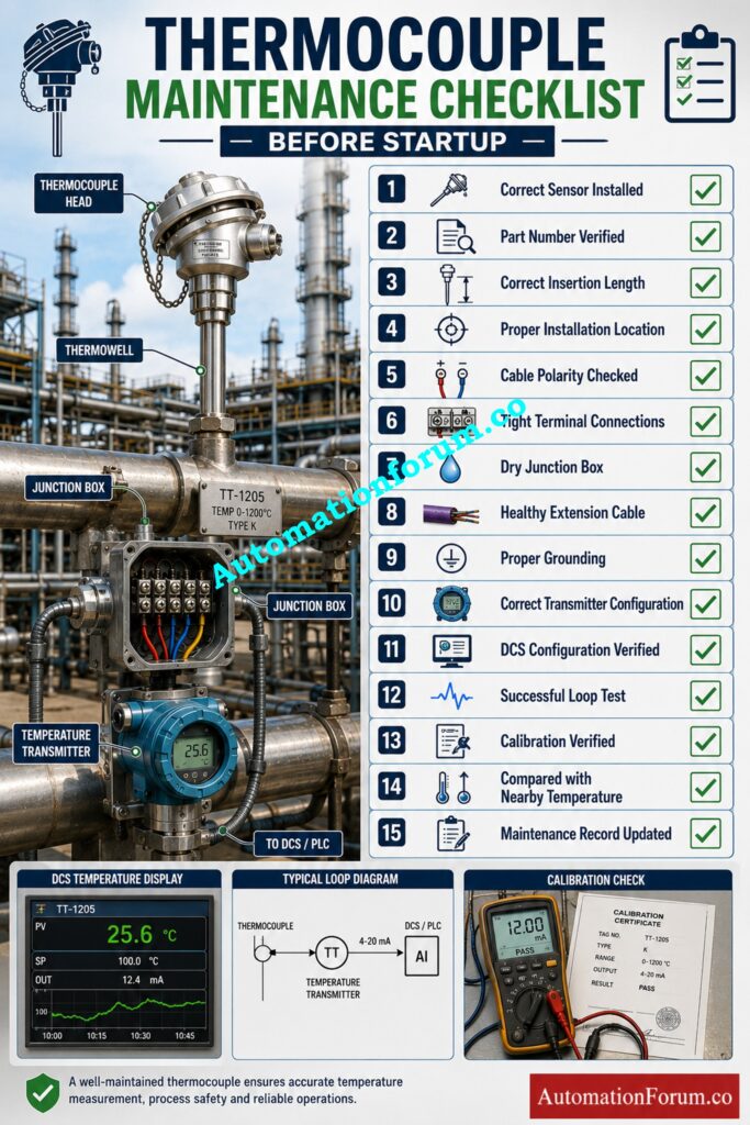
- Thermocouple Maintenance Checklist Before Returning the Loop to Service
- Conclusion: Final Recommendations for Reliable Thermocouple Troubleshooting
- Frequently Asked Questions About Thermocouple Troubleshooting
- Why is my thermocouple not reading correctly?
- What can cause an inaccurate temperature reading?
- How does a thermocouple change with a temperature change?
- How does temperature affect thermocouple readings?
- How to check thermocouple temperature?
- Why is the temperature still wrong after replacing the thermocouple?
- Can reversed polarity cause incorrect temperature readings?
- How can I confirm the thermocouple is healthy?
- Why does the reading fluctuate only during equipment operation?
- Why does moving the cable change the temperature reading?
- Can moisture affect thermocouple accuracy?
- Why should I compare with nearby temperature points?
- What is the most common installation mistake?
- What is the best troubleshooting approach?
Why Is My Thermocouple Reading Wrong Temperature After Replacement?
Common Causes of Wrong Temperature After Thermocouple Replacement
Successful execution of refinery heater shutdown maintenance activity. During a startup, the control room operator noticed that a process temperature jumped up by about 120°C after a new thermocouple was placed. The process itself was stable, the adjacent temperature points were normal but the DCS showed an absurd value. Initially, maintenance personnel questioned whether a malfunctioning transmitter was at fault, while operations wondered if the process was really overheating. Several hours were lost before the real cause was identified as an installation error.
Why Replacing a Thermocouple Does Not Always Solve the Problem
Situations like this are common across oil and gas, petrochemical, power generation, pharmaceutical, and food processing plants. Replacing a thermocouple does not automatically restore accurate temperature measurement.The fault could be anywhere along the measurement chain, sensor, extension cable, junction box, transmitter, configuration or even the control system.
Replacing transmitters, input cards or field cables without adequate diagnosis as is the usual practice results in higher maintenance expenses and longer equipment downtime. A systematic troubleshooting method allows the engineer to swiftly locate the real defect and avoid replacing extraneous components.
This article presents a proven field troubleshooting procedure used by experienced instrumentation engineers to identify the real cause of incorrect temperature readings after thermocouple replacement and restore reliable operation safely and efficiently.
Avoid Wiring Mistakes That Every Instrument Engineer Must Know: Thermocouple Wire vs. Thermocouple Extension Wire: The Complete Guide for Instrumentation Engineers
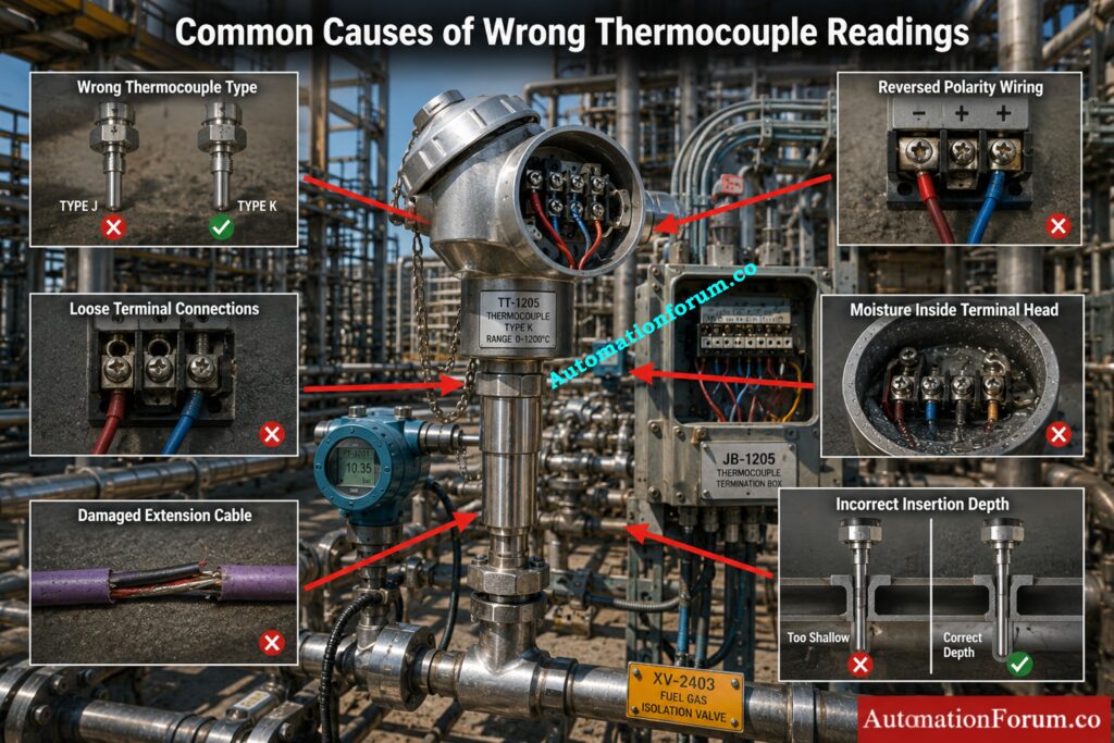
Common Symptoms of Incorrect Thermocouple Readings After Replacement
Recognising the symptom often provides the first clue to the actual problem. Experienced engineers rarely begin by replacing additional components. Instead, they carefully observe how the indication behaves before starting detailed checks.
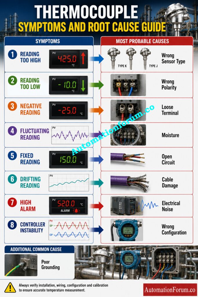
Thermocouple Reading Too High
Usually a high reading is caused by the wrong type of thermocouple being used, a faulty transmitter configuration, compensating wiring being inverted or the DCS input being configured incorrectly. Electrical interference can also lead to unnaturally high readings.
Thermocouple Reading Too Low
Poor process immersion, damaged sensing connection, inappropriate installation placement, or significant heat loss through the thermowell can all lead to a reading below expected.
Negative Temperature Reading
Negative temperatures are most often seen when the cable polarity has been reversed, the extension cable leads have been crossed or the transmitter has been setup for the wrong type of sensor.
Fluctuating Temperature Reading
Constant changes are normally loose terminals, cable problems, electrical noise, moisture in the terminal head or broken extension cables.
Thermocouple Reading Stuck at One Value
If the reading does not change when process conditions vary, this may suggest an open sensor junction, transmitter failure, improper loop wiring, or improper controller configuration.
Gradually Drifting Temperature Reading
Slow temperature drift is usually caused by moisture entering the device, bad insulation, aging extension cords, bad terminal contact, or a change in the ambient temperature in the vicinity of the junction box.
Temperature Changes When the Cable Is Moved
If the temperature indicated fluctuates when the cable is moved lightly, suspect broken conductors inside the insulation, loose terminals, damaged cable glands, or bad crimp connections.
Intermittent High Temperature Alarms
Random alarms are frequently caused by unstable electrical contacts, sporadic grounding issues, moisture contamination or electromagnetic interference from neighboring power cables.
Temperature Controller Instability
An inconsistent temperature signal directly affects the PID performance. The controller repeatedly manipulates the final control element because it is responding to false measurement and not actual process circumstances.
False Process Trips Due to Incorrect Temperature
Faulty temperature measurements can trigger safety shutdowns, burner trips, reactor protection systems or compressor interlocks even when the process temperature is really within normal operating limits.
Understanding these symptoms will assist you to narrow the investigation before opening junction boxes or replacing any other equipment.
Diagnose Sensor Problems Faster With Proven Field Testing Methods: Testing a Thermocouple With a Multimeter: A Complete Field Guide for Instrumentation Engineers
Step by Step Troubleshooting Procedure for Thermocouple Reading Wrong Temperature After Replacement
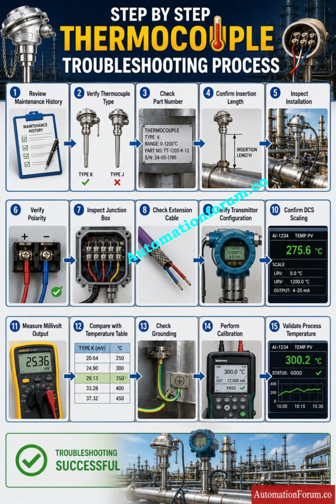
A structured troubleshooting cycle saves lost effort and unneeded replacement of equipment. Complete each step before continuing to the next.
Step 1 Review Maintenance History
- Always start with a review of the work that was done during the maintenance activity.
- Maintenance logs, work permits, calibration reports, spare parts information. Check to see if only the thermocouple was replaced or if extension cables, transmitters, junction boxes or control system setup were also changed.
- Many problems originate from changes introduced during maintenance rather than from equipment failure.
- A common mistake is assuming that every replaced component was installed correctly simply because it is new.
- Field tip: Compare photographs taken before maintenance with the current installation whenever possible.
Step 2 Verify the Correct Thermocouple Type
- Many incorrect readings result from installing the wrong sensor type.
- Verify the installed thermocouple against the instrument data sheet, equipment specification, procurement documentation and process drawings.
- Ensure the installed sensor matches the original design.
- Even identical looking sensors can produce completely different outputs.
- Incorrect sensor selection causes temperature errors across the entire measuring range.
- Corrective action involves installing the specified thermocouple rather than attempting software corrections.
Step 3 Confirm the Thermocouple Part Number
- Always verify the manufacturer’s part number.
- Field engineers occasionally discover that stores supplied a similar looking spare with different characteristics.
- Compare the installed part number with approved spare records and manufacturer documentation.
- Never rely only on the label attached to the packaging.
Challenge Your Troubleshooting Skills Like Experienced Plant Engineers: Advanced Quiz on Thermocouple Troubleshooting in Process Area
Step 4 Verify the Sensor Insertion Length
- Incorrect insertion depth affects measurement accuracy significantly.
- Compare the installed insertion length to the original drawing or the removed sensor.
- If in the process the sensing tip does not reach the proper place, the measured temperature may be substantially lower than the actual temperature of the process.
- Use of the improper thermowell or adding extra fittings may inadvertently reduce the immersion depth.
Step 5 Check the Thermocouple Installation Location
- Check that the thermocouple is fitted on the correct tapping point.
- During shutdown work involving multiple sensors, technicians may accidentally exchange installation locations.
- Cross check the equipment tag number, piping isometric, instrument location drawing, and process line identification.
- A correctly functioning thermocouple installed in the wrong location still produces incorrect process information.
Calculate Accurate Temperature Values Within Seconds Without Errors: Thermocouple Voltage ↔ Temperature Calculator
Step 6 Inspect the Mounting Arrangement
- Carefully examine the complete mounting arrangement.
- Tighten the compression fitting, thermowell, gland and mounting hardware as required.
- Vibration from mechanical looseness can eventually harm the sensor junction or generate intermittent electrical problems.
- Look for evidence of mechanical tension during installation.
Step 7 Verify Proper Process Immersion
- The sensing junction should be thoroughly exposed to representative process conditions.
- Immersion lack permits the measurement to be influenced by temperatures of surrounding metal.
- Installation depth versus engineering guidelines and historical maintenance records.
- Reinstall the sensor, if needed, with the right insertion length.
Test Your Instrument Selection Knowledge Before Real Plant Projects: Quiz on RTD and Thermocouple Selection for Instrumentation Design Engineers
Step 8 Inspect the Thermocouple Extension Cable
- Check the whole cable run between the thermocouple and the transmitter.
- Check for broken insulation, crushed areas, abrupt bends, cable couplings, visible conductors and indications of overheating.
- The cable damage is often done during building of scaffolding, insulation removal or during mechanical maintenance work.
- Replace damaged cable rather than attempting temporary repairs.
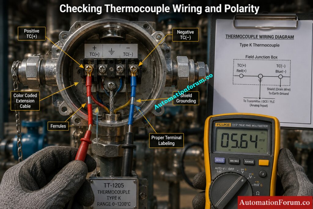
Step 9 Verify Thermocouple Cable Polarity
- Incorrect polarity remains one of the most frequent causes of wrong temperature after thermocouple replacement.
- Check that the positive and negative conductors are tied appropriately through the loop using wiring diagrams and terminal identification.
- A single reversed connection inside a junction box can produce completely misleading measurements.
- Never assume conductor colours are correct without verification.
Step 10 Inspect Terminal Connections
- Open every junction box and inspect all terminals carefully.
- Check for loose screws, corrosion, oxidised conductors, faulty crimps, broken strands and erroneous terminal assignments.
- Even a small movement can result in unreliable results under vibration.
- Retorque terminals to manufacturer’s torque specifications.
Step 11 Check for Loose Terminal Connections
- Visually check and pull each conductor lightly one at a time.
- Conductor may appear tight but be loose under the terminal clamp.
- If the connections are loose, the measurements are less stable and can cause intermittent alerts during plant vibration.
- Replace broken ferrules before rejoining conductors.
Step 12 Inspect Moisture Inside the Terminal Head
- Moisture is a typical source of erratic temperature readings.
- Look at the terminal head for moisture, water droplets, corrosion, damaged seals or degraded cable glands.
- Moisture produces leaky routes which affect low millivolt signals.
- Thoroughly dry the enclosure and replace any damaged seals before returning the loop to service.
Convert Temperature Signals Accurately Using Proven Engineering Methods: How to Convert Thermocouple Millivolts to Temperature: A Step-by-Step Guide
Step 13 Verify Temperature Transmitter Configuration
- Ensure that the transmitter is configured for the kind of thermocouple fitted.
- Verify the engineering units, sensor selection, burnout direction, damping, measuring range and diagnostic settings.
- Configuration issues are typically seen following transmitter replacement or factory reset.
- Always compare settings with approved instrument database not default values.
Put Your Industrial Temperature Expertise To The Ultimate Test: Advanced Thermocouple Knowledge Quiz: Principles, Types, and Industrial Applications
Step 14 Confirm DCS Input Configuration
- The field transmitter may be properly configured, but the technical parameters in the DCS database may be wrong.
- Check channel assignment, tag number, engineering units, alarm limits and scaling values.
- Mismatch between field configuration and control system configuration creates misleading indications even when field equipment is functioning correctly.
Step 15 Verify PLC Input Scaling
- Where temperature is processed through PLC analogue inputs, verify the scaling logic carefully.
- Compare raw input values with engineering units displayed on operator screens.
- Programming modifications performed during shutdowns occasionally introduce scaling errors that affect only one measurement point.
Master Accurate Signal Conversion For Reliable Process Measurements: Converting Thermocouple Millivolts to Temperature: Methods and Examples
Step 16 Check Compensation Settings
- Thermocouple measurement requires proper adjustment throughout the loop. Verify that the compensating mechanism as configured meets the installation design. When the setting is off, it may change the indicated temperature by a few degrees . This is especially true in areas with large ambient temperature variation .
- Compare the transmitter settings with the instrument datasheet and control system database. Resolve mismatches prior to further examination.
- A common mistake is to copy configuration from another loop and not to check the real sensor specification.
Complete Every Startup Inspection Before Bringing Temperature Loops Online: Thermocouple Commissioning Checklist
Step 17 Verify Cold Junction Compensation
- Correct measurement should work for the cold junction compensation.
- Check the reference junction temperature with a portable calibrator or transmitter diagnostics. Compare the stated ambient temperature with the actual temperature in the vicinity of the transmitter.
- If the discrepancy is large, check for defects in the transmitter, terminal block or electronics.
- Field tip: Transmitters should not be installed in locations where they will be exposed to direct sunshine or high heat from surrounding equipment that can impact reference temperature.
Step 18 Measure the Thermocouple Millivolt Output
- Disconnect the sensor from the transmitter and measure the thermocouple millivolt output with a high accuracy digital multimeter.
- Compare the measured value with standard thermocouple reference tables for the estimated process temperature.
- If the measured voltage does not correspond with the actual process condition, the fault is usually within the sensor or field wiring.
Follow This Proven Checklist To Solve Temperature Problems Faster: Check List: How to Troubleshoot a Thermocouple?
Step 19 Compare Millivolt Output With Standard Temperature Tables
- Never rely only on displayed values.
- Compare the measured millivolt output with recognised temperature reference tables for the installed thermocouple type.
- A large deviation immediately narrows the investigation towards incorrect sensor type, damaged sensor, or wiring errors.
Step 20 Check Cable Insulation Resistance
- Inspect cable insulation using an insulation resistance tester where plant procedures permit.
- Low insulation resistance may indicate moisture infiltration, damaged cable insulation or contamination in junction boxes.
- Poor insulation causes the readings to be unsteady and they get worse in wet weather.
- Don’t attempt to patch temporary insulation repairs, replace the broken cables.
Choose The Best Sensor For Reliable Industrial Temperature Control: Choosing Between Thermocouples and RTDs: A Practical Guide for Temperature Sensing
Step 21 Inspect Thermocouple Cable Routing
- Follow the entire cable path.
- Keep thermocouple extension cables away from power cables, motor feeders, welding cables and variable speed drive circuits.
- A poor route exposes the low level signal to electrical interference.
- Whenever possible, use dedicated instrument cable trays.
Step 22 Check for Electrical Noise
- Observe the temperature trend during operation of nearby large motors or switching equipment.
- Electromagnetic interference should be considered if fluctuations happen when electrical equipment is switched on or off.
- Improve cable shielding, routing and grounding if needed.
Step 23 Verify Proper Grounding
- Check complete grounding system.
- Check that shields are terminated per plant specifications and that there are no unwanted multiple grounding points.
- Poor grounding often leads to unstable measurements that cannot be reproduced in testing.
Step 24 Inspect the Junction Box Condition
- Inspect every junction box between the sensor and control system.
- Look for corrosion, insects, dirt, loose terminals, damaged glands, and cracked covers.
- Small defects often become major reliability problems during humid weather.
Step 25 Check for Damaged Extension Cable
- Walk the entire cable route.
- Look for crushed sections, abrasion, burn marks, chemical damage, or mechanical impact.
- Cable damage frequently occurs during scaffold removal and insulation work after shutdowns.
Step 26 Check for Short Circuits
- Use continuity testing to identify conductor to conductor short circuits.
- A short circuit usually causes unstable or incorrect temperature indications.
- Repair or replace the affected cable before recommissioning the loop.
Step 27 Check for Open Circuits
- Measure conductor continuity from the sensor to the transmitter.
- An open circuit normally produces burnout indication or an unrealistic temperature depending on transmitter configuration.
- Inspect every termination before replacing the sensor.
Step 28 Swap With a Known Good Thermocouple
- If uncertainty remains, temporarily install a verified thermocouple from another healthy loop of identical specification.
- If the problem disappears, the original sensor is defective.
- If the fault remains, continue investigating the remaining measurement chain.
Step 29 Verify Temperature Transmitter Calibration
- Check transmitter calibration with a certified temperature calibrator.
- Apply known thermocouple signals and check that the transmitter output matches the expected values over the entire working range.
- If it’s outside allowable tolerance, it needs to be recalibrated or replaced.
Refer the below link for the How to simulate RTDs and Thermocouples using Multifunction calibrator?
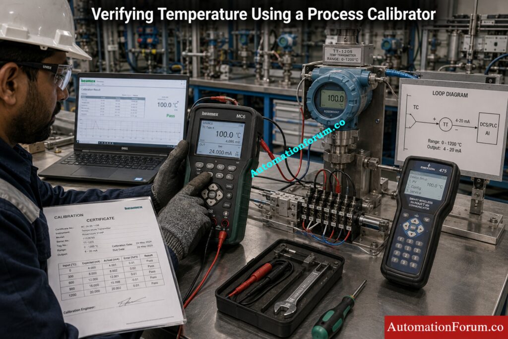
Step 30 Compare With a Portable Temperature Calibrator
- Connect a handheld process calibrator directly to the transmitter input.
- Compare the DCS reading with the calibrator output.
- Agreement confirms that the downstream measurement chain is healthy.
- Disagreement directs attention towards transmitter configuration or control system configuration.
Step 31 Cross Check With Nearby Temperature Measurements
- Compare the questionable measurement to adjacent process temperature points.
- Although exact temperatures may differ, process behaviour should remain logical.
- Large unexplained differences often indicate an instrumentation problem rather than an actual process upset.
Achieve Accurate Temperature Calibration With Confidence Every Time: How to calibrate Thermocouple Transmitter?
Step 32 Evaluate Actual Process Conditions
- Check that the process is working correctly.
- During reduced flow, bypass operation, equipment isolation, steam tracing or newly started equipment, true temperature variations may be seen.
- Never assume that every abnormal reading is an instrument problem.
Step 33 Document All Troubleshooting Findings
- Document all observations, measurements, remedial actions, configuration changes and test results.
- Good documentation avoids re-troubleshooting during future shutdowns and enables long term reliability enhancement.
- Field engineers who maintain detailed records usually resolve recurring problems much faster.
Master Every Calibration Step For Reliable Temperature Measurements: 8 Steps Calibration Procedure for Thermocouple
Thermocouple Troubleshooting Decision Table
| Observed Symptom | Most Probable Cause | How to Verify | Recommended Action |
| Temperature too high | Wrong sensor type | Check part number | Install correct sensor |
| Temperature too low | Poor immersion | Measure insertion depth | Reinstall correctly |
| Negative reading | Reversed polarity | Verify terminals | Correct polarity |
| Reading fluctuates | Loose terminals | Perform pull test | Tighten connections |
| Reading drifts | Moisture ingress | Inspect terminal head | Dry and reseal |
| Reading fixed | Open circuit | Check continuity | Repair cable |
| False high alarm | Configuration error | Review transmitter settings | Correct configuration |
| Reading changes with cable movement | Broken conductor | Flex cable during testing | Replace cable |
| Intermittent alarms | Corroded terminals | Visual inspection | Clean or replace terminals |
| Unstable controller | Electrical noise | Observe during motor operation | Improve routing |
| Burnout indication | Open sensor | Measure continuity | Replace sensor |
| Large measurement error | Wrong compensation | Verify settings | Correct compensation |
| Difference from nearby point | Wrong installation location | Check drawings | Install at correct location |
| Reading unstable in rain | Water ingress | Inspect junction box | Replace seals |
| Incorrect DCS value | Scaling error | Compare raw input | Correct scaling |
Real Plant Case Study of Wrong Thermocouple Temperature After Replacement
Problem Observed During Plant Startup
A thermocouple near the outflow of a refinery furnace was replaced during a planned shutdown since the sensor had expired its recommended service life. The startup proceeded normally until the control room indicated that the outlet temperature was at least 90°C higher than intended. Operations lowered the fire to safeguard the furnace, however the nearby temperature points were not affected.
Detailed Investigation
The repair staff initially suspected a malfunctioning transmitter and replaced it but still no difference. They then checked the DCS setup which was in agreement with the technical documents.
Root Cause Identified
The new thermocouple was found to have the correct tag, however upon field inspection it was found that the extension cable within the junction box had been attached with reversed polarity during reassembly. The wiring error was in the terminal enclosure and was therefore missed during the loop inspections.
Corrective Actions Taken
Once the polarity was corrected and the functional test re-run the temperature reading immediately agreed with the portable calibrator and neighboring process readings.
This event delayed commencement by many hours, and needless replacement of the transmitter.
Lessons Learned
A obligatory terminal verification step has been added to the maintenance review prior to loop commissioning. Every thermocouple replacement now includes polarity verification, configuration confirmation, and comparison with adjacent process temperatures before handing the loop back to operations.
The lesson was simple. A systematic troubleshooting approach identifies the actual cause far more quickly than replacing components based on assumptions.
Discover The Secret Behind Superior Temperature Measurement Accuracy: Why 4 wire RTD’s measurement accuracy is better than 2 and 3 wire RTD?
Best Practices to Prevent Wrong Thermocouple Temperature After Replacement
- Successful maintenance begins long before the new sensor is installed.
- Always verify the spare part number before leaving the workshop.
- Compare the new sensor with the removed unit.
- Check the length of insertion before tightening the compression fitting.
- Check the thermowell for deposits or damage.
- Check the polarity of the cable at each termination
- During maintenance replace broken cable glands.
- Keep terminal heads clean and dry.
- Use only approved thermocouple extension cable.
- Separate instrument cables from power cables.
- Verify transmitter configuration before energising the loop.
- Check for loops before you start the process.
- Compare measurements with adjacent instruments.
- Record all maintenance activities in the history system.
- Ask another technician to independently verify wiring before closing the junction box.
Learn The Engineering Principle Behind Better Sensor Installation: Why Install Thermowells at a 45° Angle? Engineering Logic Explained
Common Mistakes That Cause Wrong Thermocouple Temperature After Replacement
- Many troubleshooting hours are wasted because engineers assume the new sensor cannot be faulty. Sometimes new components come damaged or labelled wrongly.
- A frequent mistake is not checking the polarity verification since the conductor colors appear to be correct. Colour alone should not replace appropriate testing.
- Some personnel install sensors without verifying insertion length, leading to readings that reflect pipe wall temperature instead of process temperature.
- The configuration copied from another transmitter may not match the fitted sensor.
- Loose terminal screws are commonly overlooked until vibration of the plant causes sporadic failures.
- Extension cable damaged Sometimes remains in service as maintenance work order applied to only sensor.
- Moisture inside terminal heads is neglected and repeated failures are observed under humid conditions.
- Control systems sometimes be left out when engineering changes are made and scaled.
- Sometimes grounding methods get changed during cable replacement without any documentation.
- Before checking simple electrical defects, engineers may replace transmitters.
- Failure to match data to surrounding temperature sites can delay fault discovery.
- Poor documentation leads to the same mistake being repeated during future shutdowns.
Improve Calibration Accuracy Using Professional Temperature Measurement Tools: Master Temperature Calibrators: Precision Tools for Accurate Temperature Instrument Calibration
Thermocouple Maintenance Checklist Before Returning the Loop to Service
| Verification Item | Status |
| Correct thermocouple installed | □ |
| Part number verified | □ |
| Insertion length confirmed | □ |
| Installation location checked | □ |
| Cable polarity verified | □ |
| Terminal connections tightened | □ |
| Junction box clean and dry | □ |
| Extension cable inspected | □ |
| Grounding verified | □ |
| Transmitter configured correctly | □ |
| DCS configuration confirmed | □ |
| Loop tested successfully | □ |
| Reading compared with calibrator | □ |
| Reading compared with nearby process point | □ |
| Maintenance record updated | □ |
Conclusion: Final Recommendations for Reliable Thermocouple Troubleshooting
Replacing a thermocouple is often only the first step in restoring reliable temperature measurement. When the displayed value remains incorrect, the actual problem may exist anywhere between the sensing junction and the control system. Experienced instrumentation engineers avoid replacing components at random. Instead, they use a systematic troubleshooting approach that checks each component in the measurement chain, from installation and wiring to setup, calibration, grounding, and process conditions.
This systematic method leads to lower unnecessary maintenance costs, avoids long plant downtimes and increases measurement reliability. Assumptions are not as good as careful scrutiny. Accurate testing and thorough documentation.
If you have a new thermocouple and you are getting a surprising temperature reading then check and verify each component systematically before you conclude that the sensor is faulty. A few minutes of comprehensive diagnosis can save hours of unneeded troubleshooting and recurring maintenance.
AutomationForum has the latest technical articles on more down-to-earth industrial troubleshooting procedures, maintenance instructions and instrumentation engineering tools.
Resolve Temperature Control Issues Before They Cause Major Downtime: Temperature Controller Troubleshooting Guide: Common Problems, Causes and Solutions
Frequently Asked Questions About Thermocouple Troubleshooting
Why is my thermocouple not reading correctly?
Thermocouples can give false readings owing to faulty wiring, reverse polarity, inadequate connections, incorrect setup, or a damaged sensor. Systematically verify the whole measuring loop before changing parts.
What can cause an inaccurate temperature reading?
Incorrect temperature readings can be caused by a sensor that is installed incorrectly, not deep enough in the immersion, electrical noise, moisture intrusion, the wrong type of thermocouple or a transmitter that is not configured correctly.
How does a thermocouple change with a temperature change?
As the temperature varies, the thermocouple provides a distinct millivolt signal corresponding to the variation in temperature. In response to this signal the transmitter or control system indicates the process temperature.
How does temperature affect thermocouple readings?
The millivolt output from the thermocouple is proportional to the process temperature either increasing or decreasing. Other impacts on the displayed measurement may arise from incorrect cold junction correction or from ambient temperature.
How to check thermocouple temperature?
Measure the millivolt output of the thermocouple with a calibrated multi-meter or process calibrator and compare with standard reference tables. You can also check the reading by using a portable temperature calibrator or a known reference sensor.
Why is the temperature still wrong after replacing the thermocouple?
The problem may be in the extension cable, transmitter, junction box, configuration or control system, not the new sensor. Always troubleshoot the complete measurement chain.
Can reversed polarity cause incorrect temperature readings?
Yes. Reversed polarity is one of the most common causes of negative or inaccurate temperature indications after maintenance.
How can I confirm the thermocouple is healthy?
Measure its millivolt output and compare the result with standard temperature reference tables for the installed sensor type.
Why does the reading fluctuate only during equipment operation?
Electrical noise from nearby motors or drives may be affecting the thermocouple signal. Check cable routing and grounding.
Why does moving the cable change the temperature reading?
This usually indicates a broken conductor, loose termination, or damaged cable that creates an intermittent connection.
Can moisture affect thermocouple accuracy?
Yes. Moisture inside terminal heads or junction boxes creates leakage paths that disturb the low level thermocouple signal.
Why should I compare with nearby temperature points?
Neighbouring measurements provide a practical reference and help determine whether the problem is with the instrument or the process.
What is the most common installation mistake?
Incorrect cable polarity and wrong sensor configuration are among the most frequently encountered field issues after replacement.
What is the best troubleshooting approach?
Follow a logical sequence that verifies installation, wiring, configuration, calibration, and actual process conditions before replacing additional components.
Refer the below link for the Faulty Thermocouple Replacement Procedure in Process Area: Complete Step-by-Step Field Guide for Instrumentation Engineers
