- What is a Thermowell?
- Why Install a Thermowell at a 45° Angle?
- Importance of Pipe Size in Thermowell Design
- Standards Supporting Angled Thermowell Installation
- Frequently Asked Questions (FAQ)
- What are the guidelines for thermowell installation?
- How are thermowells installed?
- What is the API standard for thermowell installation?
- What is the standard U-length for thermowell?
- What is the IEC standard for thermowell?
- What is the EIL standard for thermowell?
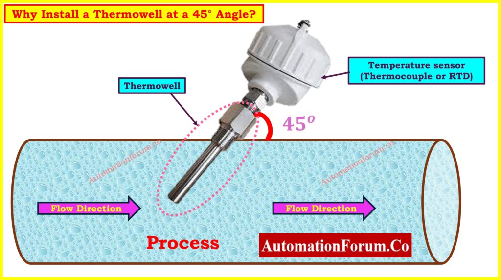
Thermowells are very important in process industries including oil and gas, chemical manufacture, power generation, and pharmaceuticals, where it is very important to get the temperature right. They protect temperature sensors from harsh process conditions. A lot of thermowells are put in at a right angle to the pipe wall, but a lot of them are put in at a 45° angle to the flow direction on purpose.
This isn’t about looks or ease of use; it’s a well-thought-out and planned engineering choice. Installing a thermowell at a 45° angle has a number of technical benefits that immediately increase the performance, safety, and reliability of the sensors.
What is a Thermowell?
A thermowell is a tube-shaped fitting that goes into a process line and lets a temperature sensor, like a thermocouple, RTD, or thermometer, detect the temperature of the process without being in contact with the fluid. It protects against pressure, corrosion, and flow-induced stresses while also letting you take out or replace sensors without stopping the operation.
But the angle at which a thermowell is put in place has a direct effect on how well it works and how long it lasts.
Explore Thermowells and Their Types: Thermowells & types of thermowells
Why Install a Thermowell at a 45° Angle?
Installing thermowells at a 45° angle to the flow of fluid has a number of important engineering benefits:
Reduced Flow-Induced Vibration
One of the most important reasons to put a thermowell at an angle is to cut down on flow-induced vibration. This happens when fluid flows around a bluff body (in this case, the thermowell) and creates alternating vortices. Resonance happens when the shedding frequency (also called the Strouhal frequency) is the same as the thermowell’s natural frequency. This can cause vibration-induced fatigue and possible mechanical failure.
The ASME PTC 19.3 TW-2010 standard, which sets rules for designing thermowells, stresses the need of avoiding resonance by looking at the thermowell’s in-line and transverse frequencies. Installing the thermowell at a 45° angle makes the cross-flow velocity much lower, which makes the vortex shedding less intense. This lowers the amplitude of the vibrations caused by the thermowell and makes it last longer.
Thermowell Insertion and Immersion Explained: Thermowell Insertion and Immersion Length
Improved Temperature Response and Accuracy
When the sensor is installed at an angle, the tip is better immersed in the fluid stream, which:
- Improves heat transfer to the sensor
- Reduces thermal lag
- Delivers faster and more accurate temperature readings
Gives temperature readings that are faster and more accurate
This is very critical in processes that are changing or moving quickly, when response time is quite vital. The sensor picks up accurate temperatures without delay or insulation from stagnant zones because it is deeper in the active flow channel.
How to Specify a Thermowell Properly: How to specify a thermowell?
Lower Pressure Drop and Better Flow Dynamics
Installing thermowells at an angle makes it easier for flow to happen than installing them straight up and down. This leads to:
- Reduced pressure drop
- Less turbulence and energy loss
- Improved flow profile integrity
In procedures where the flow is sensitive, such custody transfer, it is very important to keep the flow’s integrity. Changes in fluid velocity or turbulence can cause measurement errors or system inefficiencies.
Easier Maintenance and Accessibility
A 45° angle typically makes it easier to get to things physically, especially in:
- Overhead pipe runs
- Insulated or jacketed piping
- Tight or congested areas
This simplifies removal, inspection, and calibration of the temperature sensor, making it easier and safer for technicians to work on the system especially under time-critical maintenance schedules.
Refer the below link to understand Why RTD Temperature Sensors are Installed Downstream of Orifice Plates?
Importance of Pipe Size in Thermowell Design
placing a thermowell in at a 45° angle not only helps lessen vibrations caused by flow, but it also makes the thermowell last a lot longer. Lowering the wake frequency reduces mechanical stress, especially in applications with high speeds or high pressures. A slight adjustment in how something is installed can have a large effect on how long it lasts and how often it needs to be serviced.
Furthermore, it is imperative to specify the minimum pipe size when installing thermowells. This is not just a dimensional issue; it directly influences the wake frequency, fluid velocity, and the suitability of the thermowell design. This interface specification must be addressed by the instrumentation engineer as part of a complete system design. Unfortunately, many discussions and guidelines overlook this crucial factor, resulting in ineffective or even dangerous installations.
Also, let’s be clear that utilizing imprecise “rules of thumb” is not the same as good engineering judgment. Established pipeline and instrumentation standards, not informal or anecdotal references, should guide good engineering practice. To make sure that all projects are safe and work well, they must be precise, consistent, and follow design standards.
Follow This Thermocouple Commissioning Checklist: Thermocouple Commissioning Checklist
Standards Supporting Angled Thermowell Installation
Even if they don’t specifically say that the angle should be 45°, a number of international and industry standards do recognize or promote the usage of angled thermowells.
1. ASME PTC 19.3 TW-2010
This is the Performance Test Code that explains how to analyze thermowell vibration, stress, and fatigue. It gives ways to figure out if a thermowell is likely to fail because of vortex-induced vibration. It doesn’t say what angle to use, but it does say that angled installations lower the effective cross-flow velocity, which makes things safer mechanically.
2. API RP 551
The American Petroleum Institute’s Recommended Practice 551 gives rules for how to measure temperature in refineries and processing plants. It says that for angled installations, the immersion length, or “U-length,” should be between 2 and 5 inches to make sure that the measurement is precise and responsive without losing too much heat conduction. This makes sure that the sensor is fully involved in the fluid stream without putting too much stress on it.
3. IEC 60584
The International Electrotechnical Commission (IEC) standard 60584 discusses about how accurate, well-built, and tolerant thermocouples should be. It doesn’t directly tell you how to set up thermowells, but it does help making sure that the materials are compatible and that the sensors are in the right spot for the best performance, whether the installation is straight or inclined.
4. ISA RP12.2
This Instrument Society of America Recommended Practice lists safe ways to install sensors and thermowells, especially in places where they could be dangerous. It helps with the right sensor orientation, protection, and materials, which makes it clear that the angle of installation needs to be changed to fit the circumstances of the process and the mechanical limits.
5. EIL (Engineers India Limited) Standards
EIL is a well-known engineering consulting organization in India that also gives project-specific standards and guidelines for choosing and installing thermowells, primarily in the oil, gas, and petrochemical industries. EIL standards usually stress uniform U-lengths, material grades, and insertion angles to make sure that big projects are all the same.
Instrumentation Engineers Must-Have Drawing Checklist: 82 Essential Drawings and Documents for Instrumentation and Control Engineers
Frequently Asked Questions (FAQ)
What are the guidelines for thermowell installation?
Here are some rules for installing a thermowell:
- Ensuring adequate immersion (typically 2-5 times the diameter)
- Avoiding resonant vibration (as per ASME PTC 19.3 TW)
- Using correct material based on fluid composition and temperature
- Positioning at an angle (e.g., 45°) when needed to reduce vibration and improve accuracy
- Proper welding or threaded attachment to prevent leakage
- Specifying pipe size and velocity during design
RTD Testing Methods You Should Know: RTD Testing Methods
How are thermowells installed?
Here are some rules for installing a thermowell:
- Screwed into a pipe fitting with threads
- Flanged: Attached to a matching flange on the pipe using bolts
- Welded: welded right onto the pipe
- Welded using a socket or Van Stone: Depending on the degree of pressure and how easy it is to get to
You need to choose the installation angle, depth (U-length), and orientation based on how the fluid flows, how easy it is to get to, and the risk of vibration.
Use this RTD Commissioning Checklist: RTD Commissioning Checklist
What is the API standard for thermowell installation?
The standard that applies is API RP 551, which:
- Suggests immersion lengths for thermowells (usually 2 to 5 inches)
- Stresses precision, stability, and cutting down on vibrations
- Supports angled installations to make things work better
API rules are very important for oil and gas and refining applications.
Troubleshoot Thermocouples with This Checklist: Check List: How to Troubleshoot a Thermocouple?
What is the standard U-length for thermowell?
There is no U-length that works for everyone. But the usual lengths are
- 2.5”, 4.5”, 6.0”, and 9.0”
- Custom lengths based on process pipe size and application
API RP 551 says that for inclined thermowell installations, the sensor should be immersed between 2 and 5 inches, measured from the pipe wall to the tip of the sensor.
Step-by-Step RTD Calibration Procedure Guide: 8 Steps RTD Calibration Procedure
What is the IEC standard for thermowell?
IEC 60584 gives rules for thermocouples that cover:
- Accuracy classes
- Material selection
- Tolerances
It doesn’t directly define thermowells, but it does encourage their use by setting criteria for sensor design and compatibility for the housing (including wells).
What is the EIL standard for thermowell?
Engineers India Limited (EIL) has its own standards that are utilized in EPC and oil and gas projects in India. These usually include:
- U-length and stem diameter specifications
- Flange ratings (150#, 300#, etc.)
- Approved materials for different services (SS316, Monel, etc.)
- Insertion angles and application-specific installation details
EIL standards are used in the petrochemical, refinery, fertilizer, and pipeline industries to make sure that all large-scale projects are done in the same way and with the same level of technical accuracy.
Understand Temperature Measurement and Calibration Principles: Temperature Measurement: From Principles to Calibration
Placing a thermowell in at a 45° angle is a tried-and-true method that makes temperature measurement systems in high-performance industrial settings more reliable, accurate, and safe. It makes it easier to get to in tight locations, lowers vibration caused by flow, and enhances thermal response. These benefits aren’t simply ideas; they are based on sound engineering research and supported by international standards including ASME PTC 19.3 TW-2010, API RP 551, and IEC 60584.
Engineers can make sure that thermowells work as well as possible by using a data-driven and standards-based approach. This gets rid of guessing and “rules of thumb.” When you see a thermowell that is tilted, remember that it is not just about looks; it is also about function, accuracy and safety.
Refer the below link to Select the Right Thermocouple for Temperature Measurement Applications